A good chance to tweak it. I had one client replace all the elecos with polys (if he could fit them). Made for a serious upgrade. A real sleeper sleeper.
dave
dave
so here we go then
Stripped down the first amp, this was a bit of a basket case so nothing else to do to it realy but use it for parts
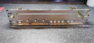
it does have a good chassis though which im going to use along with the rear panel.These have been washed, cleaned and dried.The rear panel lower half is going to be re sprayed.
The donor amp i will use the main board, which is going to be stripped of everything, then cleaned, then reassembled.
I may use some of the old parts, like resistors etc if they are ok, but i am going to put new transistors in(with the exception of the output, ill keep the original motorola's), and it will have all new caps.(i dont normaly replace them all but with something like this it is worth it.)
so here we go them with the first set of progress pics
Stripped down the first amp, this was a bit of a basket case so nothing else to do to it realy but use it for parts
it does have a good chassis though which im going to use along with the rear panel.These have been washed, cleaned and dried.The rear panel lower half is going to be re sprayed.
The donor amp i will use the main board, which is going to be stripped of everything, then cleaned, then reassembled.
I may use some of the old parts, like resistors etc if they are ok, but i am going to put new transistors in(with the exception of the output, ill keep the original motorola's), and it will have all new caps.(i dont normaly replace them all but with something like this it is worth it.)
so here we go them with the first set of progress pics
Attachments
-
 CHASSIS CLEAN 2.jpg434.3 KB · Views: 774
 -
 CHASSIS CLEAN.jpg500.4 KB · Views: 609
 -
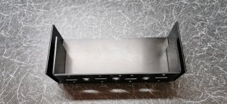 heatsink before spraying and possible upgrade.jpg505.1 KB · Views: 623
 -
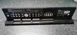 rear cleaned before spraying.jpg469.3 KB · Views: 842
 -
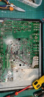 rear of old board, not worth keeping.jpg651 KB · Views: 841
 -
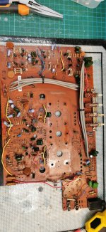 Top of old board stripped of components.jpg529 KB · Views: 881
Wow! That's a lot of work. Why not simply wash the board and dry it well? Flux cleaner usually dissolves whatever grime is there. Then just clean with distilled water and dry.The donor amp i will use the main board, which is going to be stripped of everything, then cleaned, then reassembled.
If the amp has any polystyrene components note that the solvents will eat them, so in that case use dish soap and distilled water. Wash with distilled water after to remove the soap residue.
Also be careful around the switches and pots (if there are any) as they may not be wash tight.
OTOH, resistors are cheap. If you're going through the trouble of removing all the parts to rebuild the amp you might as well put in some 1% tolerance metal film resistors.I may use some of the old parts, like resistors etc if they are ok, but i am going to put new transistors in(with the exception of the output, ill keep the original motorola's), and it will have all new caps.(i dont normaly replace them all but with something like this it is worth it.)
Tom

Yes they certainly are, and i have looked at this, but it is how to apply a heatsink to themWait a minute here… is that PCB actually drilled for both TO-3 AND TO-3P? Looks like it to me - I see a trace going to a center hole. That would solve the old 2N3055 dilemma once and for all -“eff it I’m putting in good TO-247’s”, without a kluge of wires.
so im taking some advisement here as well after comments above from @tomchr and people like @Mooly so thanks for that because in not going to take every component out.
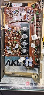
I am going to remove all of the transistors though, because as you can see from the photo's its been 'got at' as mooly would say, and ive worked on alot of these not to know what was proberbly an 'after' job, and it has a fault anyway that hopefully will be cured during the strip down and checks.
some of the transistors are mix and match, some alternate replacements, and i have enough original spares to put back original matched pairs for example of either RCA or motorola on the outputs.
The other ones i will test and put back.
I will remove any components that might get saturated with water, breakers ETC before i wash it, but i do agree with you guys, there realy isnt any need to remove all of the components
I am going to replace some of those old large resistors though with film ones as they are quite crumbly
I am going to recap it all as well.
I am also going to rewire it with new cables ,although i will keep the screened ones.
i havent decided yet if im going to leave all those little jumper wires on top yet or put them underneath, this will make it look alot tidier on top.
One ambitious thing im going to attempt
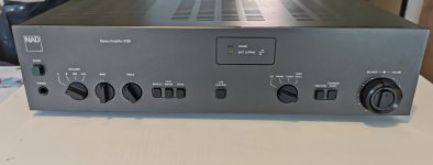
There is soft clipping on the amp, but never an indicator LED on the front, so if i can find the right type set and colour im going to put an LED on the front, but i have a way to go to investigate if this can be done and look right.
Im also thinking of replacing the 5 no red power LED'S with different colours(not sure anout this one yet.i might try it out first and see what it looks like)
possibly change the power mains LED to green (again not sure yet)
work done today so far,marked up all of the wiring and removed the transformer.
most things are marked up point to point, but at this stage im not taking any chances.
by the end of the day it will all be stripped and ready for cleaning.
Attachments

its been 'got at' as mooly would say
Oh yes 🙂 that covers a multitude of sins.
There is soft clipping on the amp, but never an indicator LED on the front, so if i can find the right type set and colour im going to put an LED on the front, but i have a way to go to investigate if this can be done and look right.
The soft clip is just a passive network that softly clips the input signal. It relies on knowing what peak input voltage will cause the amp to clip and simply limiting the input between those levels. Two diodes and a reference voltage is how they do it.
You could make a clipping indicator but you would probably never see it come on. It would need a bit of active circuitry to do this.
what i meant was, you cant tell if it is on or not, the switch is at the rear.Oh yes 🙂 that covers a multitude of sins.
The soft clip is just a passive network that softly clips the input signal. It relies on knowing what peak input voltage will cause the amp to clip and simply limiting the input between those levels. Two diodes and a reference voltage is how they do it.
You could make a clipping indicator but you would probably never see it come on. It would need a bit of active circuitry to do this.
on other models there is an led to indicate is it is on or off like attached
Attachments
Not easy but I'll say it probably can be done. Without the obvious option of a spare set of contacts on the switch you would need a circuit that looks at the DC conditions in the soft clip circuit and uses the change in those to switch an LED.
Something like a 'Window Comparator' using an opamp should be doable or simply using an opamp as a comparator. So as a minimum its an opamp, four or five resistors to set the levels, an LED and a power supply. You have no low voltage rails that I can see and so you need a simple resistor and Zener supply. It would probably be suitable to make it all single rail and have just one supply to the opamp.
Something like a 'Window Comparator' using an opamp should be doable or simply using an opamp as a comparator. So as a minimum its an opamp, four or five resistors to set the levels, an LED and a power supply. You have no low voltage rails that I can see and so you need a simple resistor and Zener supply. It would probably be suitable to make it all single rail and have just one supply to the opamp.
This is a good opportunity to quit searching for the same old hometaxial semis and do something different and potentially better.Yes they certainly are, and i have looked at this, but it is how to apply a heatsink to them
In regard to replacing TO3 power transistors with TO247, TO218 or even ancient TOP-3 plastic moulded types, this should be straightforward because their pin arrangement was originally designed for just that kind of mounting compatibility with the older TO3 semis and their heatsinks. The only difficult part is bending the pins down to pass through the PCB holes at the correct distance from the single mounting bolt hole.
Otherwise, you'll also need some new mica pads to suit TO3P/TO247/TO218 semis and I'd check that the heatsink also needs drilling to a diameter that clears any insulation sleeving, as needed on the leads and bolt that will be passing through both heatsink and PCB.
Last edited:
so questions then as im thinking of doing thisThis is a good opportunity to quit searching for the same old hometaxial semis and do something different and potentially better.
In regard to replacing TO3 power transistors with TO247, TO218 or even ancient TOP-3 plastic moulded types, this should be straightforward because their pin arrangement was originally designed for just that kind of mounting compatibility with the older TO3 semis and their heatsinks. The only difficult part is bending the pins down to pass through the PCB holes at the correct distance from the single mounting bolt hole.
Otherwise, you'll also need some new mica pads to suit TO3P/TO247/TO218 semis and I'd check that the heatsink also needs drilling to a diameter that clears any insulation sleeving, as needed on the leads and bolt that will be passing through both heatsink and PCB.
i can make my own mica pads
so the main question is will it make any difference/improvement to the actual sound output?
i shouldnt need it if i do it the same way as attachedNot easy but I'll say it probably can be done. Without the obvious option of a spare set of contacts on the switch you would need a circuit that looks at the DC conditions in the soft clip circuit and uses the change in those to switch an LED.
Something like a 'Window Comparator' using an opamp should be doable or simply using an opamp as a comparator. So as a minimum its an opamp, four or five resistors to set the levels, an LED and a power supply. You have no low voltage rails that I can see and so you need a simple resistor and Zener supply. It would probably be suitable to make it all single rail and have just one supply to the opamp.
Attachments
Thanks but please edit thread title (ask a moderator for help if you can´t on your own) to include the "NAD 3020" string in it.
Plain "coming soon" means NOTHING by itself and will NOT show up in "NAD 3020" searches for those interested.
Plain "coming soon" means NOTHING by itself and will NOT show up in "NAD 3020" searches for those interested.
yes that is fair comment, i will ask them to change it,i didnt realise TBH as this is something i did a while agoThanks but please edit thread title (ask a moderator for help if you can´t on your own) to include the "NAD 3020" string in it.
Plain "coming soon" means NOTHING by itself and will NOT show up in "NAD 3020" searches for those interested.
Have you got those spare contacts on the switch though?i shouldnt need it if i do it the same way as attached
Thread title changed as well 🙂
You can always replace TO-3’s with flat packs if you are willing to work for it. The biggest problem is that for a customer repair job it’s not really proper to go drilling extra holes in a PCB and route wires where there weren’t any. But that PCB already has a center connection properly patterned for the collector lead! That completely eliminates the reason WHY you’re not supposed to go doing that on a customer repair. The board was MADE for TO-3Ps, you can USE them.This is a good opportunity to quit searching for the same old hometaxial semis and do something different and potentially better.
In regard to replacing TO3 power transistors with TO247, TO218 or even ancient TOP-3 plastic moulded types, this should be straightforward because their pin arrangement was originally designed for just that kind of mounting compatibility with the older TO3 semis and their heatsinks. The only difficult part is bending the pins down to pass through the PCB holes at the correct distance from the single mounting bolt hole.
Otherwise, you'll also need some new mica pads to suit TO3P/TO247/TO218 semis and I'd check that the heatsink also needs drilling to a diameter that clears any insulation sleeving, as needed on the leads and bolt that will be passing through both heatsink and PCB.
Good.
That said, TO3P/TO218/TO247 WERE made to match older TO3 metallic heatsinks and PCBs, only they were somewhat optimistic and you have to bend leads down quite close to the body so be careful.
But I do it all the time, including my old 2N3055 amps which I have been making for 50 years now, thousands still working out there.
Way back then, it was THE workhorse/industry standard.
And sometimes modern flat legs are slightly too wide for skinny TO3 metallic leg holes, but a 1.25mm drill solves that.
EDIT: I missed Ian Finch´s post saying about the same.
No harm done, two people agreeing on same suggestions 😉
A good mate 👍Good.
That said, TO3P/TO218/TO247 WERE made to match older TO3 metallic heatsinks and PCBs, only they were somewhat optimistic and you have to bend leads down quite close to the body so be careful.
But I do it all the time, including my old 2N3055 amps which I have been making for 50 years now, thousands still working out there.
Way back then, it was THE workhorse/industry standard.
And sometimes modern flat legs are slightly too wide for skinny TO3 metallic leg holes, but a 1.25mm drill solves that.
EDIT: I missed Ian Finch´s post saying about the same.
No harm done, two people agreeing on same suggestions 😉
What I like to do with LED indicators is to drill a 1 mm through hole in the panel. Then drill a 5 mm counterbore centred at the 1 mm hole from the inside. Leave 0.5-1 mm of panel thickness (or more if you don't trust your skills/tools). Then epoxy the LED into the counterbore. That gives you a 1 mm diameter dot on the front panel for the indicator. I think it looks really classy especially when fitted with a pretty HeNe Red LED.There is soft clipping on the amp, but never an indicator LED on the front, so if i can find the right type set and colour im going to put an LED on the front, but i have a way to go to investigate if this can be done and look right.
Tom
so a couple of changes im making to the rear of the amp
im going to put in gold plated cinch RCA'S and also going to replace the bare wire grab terminals with ones that accept banana plugs as well as bare wire, as they did on the A and B versions
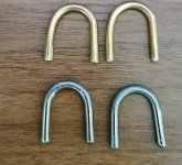
also i have made by hand some new pre amp jumpers so should smarten it up a bit, make it a bit different👍
im going to put in gold plated cinch RCA'S and also going to replace the bare wire grab terminals with ones that accept banana plugs as well as bare wire, as they did on the A and B versions
also i have made by hand some new pre amp jumpers so should smarten it up a bit, make it a bit different👍
Attachments
- Home
- Amplifiers
- Solid State
- NAD 3020 project, strip down and upgrade.