Ideal summing of two hot and cold signals from mono AK4499EXEQ

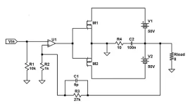
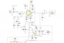
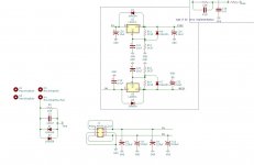
In the AK4499EXEQ data sheet, they have a recommended mono external circuit summing the two hot and cold lines together after a passive LPF stage. I am using an active LPF through an FDA and need to sum the signals before the LPF. What is the ideal way to sum two hot and two cold signals? The data sheet is unfortunately very vague when it comes to mono descriptions.
Screenshot 2025-03-18 at 13.16.41.png

Rewiring a Fidelity Research FR-64S

I just received a Fidelity Research FR-64s. I'd like to rewire it. I've done some research on the web but I can't see the way to disassemble it. It appears from photos on the internet that the cap on the dynamic VTF knob must come off but I don't know the trick to remove it without damage. Any guidance will be most appreciated.

EDIT March 2023: I've now rewired several of the FR-64 series (S and fx). I'm attaching a document with quite a few photos to the end of this first post

IMG_0077.jpg

Attachments

Anyone have luck repairing a Proceed Amp5?

I have one with one channel down. I started by removing and testing all the electrolytic caps. Half were out of spec and a couple pegged my ESR meter.
I replaced them all. After, it still off on protection. If I pull the 10 pin ribbon connector off the bad board, the other 4 power up normally. I also swapped positions in the amp and the problem follows the bad board. Funny thing is after sitting on the bench for about 10 months, it powered up with no faults. While it was powered up, I tested for DC on the speaker outs. #1 is the one causing the fault but when tested while running my voltage readings were
#1 -0.975
#2 -0.972
#3 -1.077
#4 -0.962
#5 -0.945

I suspect #3 will be the next one to cause grief but it's not tripping protection now. After leaving it powered up for over 48 hours, It went off on protection again. After, all DC readings were the same but #1 was now
-2.375. Hoping to fine someone that's had luck with these as Harmon won't provide manuals or schematics.😡

Introduction to this Awesome Forum

Hello,

Nice to meet everyone, i have been browsing these forums for a little while. But, I finally decided to start posting and contributing. I mainly focus in loudspeaker design, synthesizer design and amplifiers. I'm a novice in all these aspects, but i love it so much i decided im going to go back to school for EE! I already have a few projects that i'm exicted to share and cultivate some feedback and deisgn advice from the wonderful people here! My end plans is open source and release everything being the CAD Files, buylist and other stuff for other people to build and learn aswell.

Best,
Snubs

First M2M Design and Build Progress

Hello,

This post is to catalouge my first build and at the end i'm going to release all the files as-well. Goals were to design something similar to amphion in regards to thier passive studio monitors. Below Is the project information and photos:

Waveguides:
6.5 inch wave-guide
Credits to somasonus!
https://www.somasonus.net/waveguides

Woofers:
RS-180S
https://www.parts-express.com/Dayto...ence-Shielded-Woofer-8-Ohm-295-364?quantity=1
Tweeter:
SB26CDC
https://www.madisoundspeakerstore.com/tweeters/sb-acoustics-sb26cdc-c000-4-alum-ceram-dome-tweeter/
Passive Radiators:
DSA215
https://www.parts-express.com/Dayto...inum-Cone-Passive-Radiator-295-549?quantity=1
(Couldn't find a 7 inch passive radiator)

When i get the enclosure finished, i will start measuring and post some measurements! I'm still quite a newbie, but this project is turning out good so far! We'll see when the measurements start. Also, i do have a question about damping PR and Ported designs. What materials do you guys like to use and how much dampening do you guy's shoot for in these designs?

Attachments

  • IMG_0430.jpg
    IMG_0430.jpg
    314.9 KB · Views: 24
  • IMG_0439.jpg
    IMG_0439.jpg
    367.8 KB · Views: 23
  • IMG_0440.jpg
    IMG_0440.jpg
    402.8 KB · Views: 24
  • IMG_0441.jpg
    IMG_0441.jpg
    289.5 KB · Views: 22
  • IMG_0475.jpg
    IMG_0475.jpg
    395.1 KB · Views: 24
  • Like
Reactions: kalasbarnet

Questions about crossover filter for a SB Acoustics SB21 on a Somasonus 4" waveguide

Has anyone simulated a filter for the Somasonus 4" waveguide and sb-acoustics-sb21 tweeter?
I will try to mate this combination to a Kef b110.
Thus I'm searching a circuit layout that could lineraise the output from the waveguide, and then I hope to be able to alingn that with the Kef low pass filter.
Any comments?

MiniDSP 2x4 HD with UMIK-1

Barely used MiniDSP 2x4 HD and UMIK-1 signal processor/electronic crossover and measurement microphone. Purchased in 2021 for a speaker project it took much too long to finish.... used for a couple of months in 2024. Works flawlessly, except for the original wall wart that had to be replaced (replacement included; original discarded with extreme bias). All original boxes and parts included. $200 shipped to the USA. You will need a license for the software, which I can transfer to you after purchase (MiniDSP allows transfer).
IMG_4580.jpeg
IMG_4581.jpeg
IMG_4582.jpeg
IMG_4583.jpeg
IMG_4584.jpeg
IMG_4585.jpeg

Attachments

  • IMG_4579.jpeg
    IMG_4579.jpeg
    360.9 KB · Views: 26

ZCA: simple and easy to build class A single MosFET amplifier

I know, I know, we already talked about it here:

Class A Mosfet Amplifier and PS

and here:

ZCA 5 watt mosfet amp .

But I liked to refresh this fine project by Mark Houston ( AUS ) and update it:

DIY Class-A 2SK1058 MOSFET Amplifier Project .

So, on post # 4 the amp circuit ( one channel shown ) and the power supply.

You can easily understand why the author called it ZCA: Zero Components Amplifier.

This is the same philosophy that inspired Nelson Pass's Zen Amplifiers:

( PassDiy )

( and Nelson himself defined this project "all very cool" here:

Class A Mosfet Amplifier and PS )

the less components on the signal path, the less distortion it will go through.

Flawless reasoning, theoretically, but then there's real life: in front of a simple T-Amp, digital amplifier where the signal is compared, chopped, filtered and re-filtered by tenth of components, the ZCA is less brilliant and detailed ( not to speak about output power, consumption, dimensions and weight ! ), but achieves more musicality, in my opinion.

Anyway don't ask me to describe a sound by words, please. Frank Zappa used to say that is like dancing the architecture ! If you are interested, please build it and listen by yourself.

Some other good points:

- it's quite simple, so everyone can build it, beginners too

- there's no need to use printed boards, it can be soldered directly or using tag stripes

- it can be bunched together with components that generally are already in your drawers

- it can be easily customized, changing Mosfet or power supply and voltages and currents, and this is the most fun !

and less good points:

- like all class A amplifiers, the power consumption is huge, with an output power of few watts. So no difficult loudspeakers: it can't manage them

- don't try to put it in a cigarette packet size case: mosfets and load resistors get quite hot, they need generously dimensioned heatsinks

This is not necessarily a drawback, it can be a good reason to build cases as such, at last ( post # 4 ).


As for me, I choosed a less traditional configuration, but more stylish, maybe, with separate power supply, less traditional too, a little less stylish ...

In the next episodes I'll give you more details ( if someone is interested ... ), starting from the mosfet choice, as the original Hitachi 2SK1058 are out of production.

Ciao.

P.S.: for those people who can't wait, they can spoiler how the story ends here ( in italian, sorry ... )

https://melius.club/topic/315705-zc...e-da-realizzare/?tab=comments#comment-7142851

Transnova anyone?

A few days ago, I posted some questions about the Transnova amplifier design in the “acoustat-answer-man-is-here” discussion group in case he could share any insights from his time at Acoustat, where the design originated. I know he focuses on speakers and didn’t have much he could share. So, I mentioned I would bring up the topic on the solid-state group.

Over the years, I’ve read through a number of Jim Strickland's notes & schematics on the early Acoustat TNT Transnova amps (TNT-200, TNT-120) while comparing to the later Hafler Transnova versions (9500/9300, 9505/9303 – Hafler made other Transnova models; I just care about the Hafler Transnova designs that use Lateral MOSFETs). Some of Jim's earlier Transnova papers describe something called "complementary" feedback, which looks to be essentially positive feedback being applied to perform some error correction/cancellation. It looks like that aspect of the unique feedback arrangement was phased out of the Hafler designs. It is R26 in the TNT schematic snippet (blue) attached and Rc in the (attached) patent writeup. I don’t see a similarly located resistor is not present in the Hafler version (yellow attached schematic snippet).

Although both driver circuits are able to pump quite a bit of current into the MOSFETs (at least 40mA), I have read that Hafler front-end improved on the linearity vs. the Acoustat front-end. So, I’m curious if the complementary feedback was dropped because it was viewed as unnecessary with the “new & improved” driver circuit or were there other reasons?

I've heard the Hafler version model 9500 played through some nice electrostatics and my old Kef 104.2 speakers and liked what I heard but have never heard the Acoustat TNT models...

I know a few others around here have commented that they didn’t care for the sound of the Transnova design (anatech, djk, etc.); I couldn’t tell if they referred to the earlier Acoustat version or later Hafler version (or both).

While roaming around through the discussions, from time to time, I see some people around here post about experimental designs they have built that are somewhat similar (low voltage front-end driving grounded source Lateral MOSFET output stage that has voltage gain and floating, higher voltage rails), for example, Juma’s nice “Transnova-Schade OS/Amp. I’ve also seen the AES paper and Linear Audio article written by John Vanderkoy (and others) that uses a high performance op amp as the front-end driver for the same output stage instead (image from abstract attched). One of the key differences is Acoustat’s Tranova approach configure the discrete design front-end as a transconductor with local negative feedback around the output stage (Juma does also), while Vanderkooy’s approach uses the op amp as just a voltage gain block and the output stage has no local negative feedback.


Anybody else out there playing with this design? Any of you even happily cloned either the Acoustat or Hafler Transnova amps?

I attached some reading material that was available freely. Some of this seems harder to find now.

mlloyd1

1742238531291.png


1742238560764.png

Attachments

Interest in Siemens KS capacitors

Hello.
Im sending out a probe to check if theres interest in a lot of Siemens KS capacitors.
I have $0.40 per piece in mind, and discount on larger portions. Or all.. i will require a minimum sale .
Perfect for riaa and filters.
Datasheet added..
EU prefered.

402 pF – 160 V – B31521-B1401-K200 – 125 pcs
760 pF – 160 V – B31521-B1761-F000 – 25 pcs
2150 pF – 100 V – B31531-A1212-F500 – 125 pcs
24300 pF – 160 V – B31521-B1262-F300 – 25 pcs
1580 pF – 160 V – B31521-B1152-G800 – 125 pcs
4640 pF – 63 V – B31531-85462-F400 – 125 pcs
249 pF – 630 V – B31861-F6247-F900 – 58 pcs
1890 pF – 160 V – B31861-A1182-F900 – 150 pcs
37400 pF – 63 V – B31521-C5373-F400 – 25 pcs
1270 pF – 100 V – B31531-A1122-F700 – 125 pcs
3830 pF – 100 V – B31531-A1382-F300 – 125 pcs
4750 pF – 100 V – B31531-A1472-F500 – 125 pcs
402 pF – 63 V – B32531-A5601-H200 – 35 pcs

Attachments

  • Locked
Food for thought

Abstract​

This document presents a budget-friendly 3-way bookshelf speaker pair designed to rival popular models like the Polk ES15 and ELAC B6.2, which retail for $250–$300 per pair. The design achieves a frequency response of 34 Hz to 20 kHz (±3 dB), sensitivity of 86.5–87 dB, and power handling of 200 W, using off-the-shelf components and a slanted baffle for improved time alignment. The total cost is approximately $371.64 per pair. This publication details the design process, VituixCAD simulations, performance metrics, and a comparison to five well-regarded speakers in the $200–$1000 range, including horizontal and vertical dispersion analysis.

Introduction​

Bookshelf speakers are compact audio systems designed to deliver high-quality sound in small to medium-sized rooms. This project aims to create a pair of 3-way bookshelf speakers that offer superior performance to commercial models like the Polk ES15 and ELAC B6.2 at a similar price point. Unlike typical 2-way speakers, which use one driver for bass and midrange and another for treble, this 3-way design dedicates separate drivers to bass, midrange, and treble, enhancing clarity and detail. Key features include a slanted baffle for time alignment, a 4 Ω woofer to compensate for bass loss, and a carefully tuned crossover. The design was optimized using VituixCAD simulations and is ideal for DIY enthusiasts seeking professional-grade sound on a budget.

Design Overview​

1. Driver Selection and Specifications​

  • Woofer: Dayton Audio DCS205-4 (8", 4 Ω)
    • Handles bass up to 450 Hz with 100 W RMS power handling and ~91 dB sensitivity (boosted by 4 Ω impedance).
    • Chosen for its ability to compensate for baffle step loss, where bass weakens as sound diffracts around the enclosure.
  • Midrange: Dayton Audio RS100-8 (4", 8 Ω)
    • Covers 450 Hz to 3 kHz with 60 W RMS power handling and 86.5 dB sensitivity.
    • Selected for its clarity in critical midrange frequencies.
  • Tweeter: Dayton Audio DC25T-8 (1" Titanium, 8 Ω)
    • Handles frequencies from 3 kHz to 20 kHz with 80 W RMS power handling and sensitivity padded to ~87.5 dB.
    • Chosen for its smooth high-frequency response and affordability.

2. Enclosure Design​

  • Dimensions: 10" W × 16" D (base) × 22" H, slanting to 14" D at the top (10° angle).
  • Woofer Chamber: 1.0 ft³, ported, tuned to 34 Hz with a 2" × 4" flared port for extended bass.
  • Midrange Chamber: 0.06 ft³, sealed to isolate midrange frequencies.
  • The slanted baffle ensures sound from all drivers reaches the listener simultaneously, improving phase coherence.

3. Crossover Design​

  • Type: Dayton Audio XO3W-450/3K (8 Ω) with crossover points at 450 Hz and 3 kHz.
  • Adjustment: A 4 Ω resistor pads the tweeter’s sensitivity to match the system average.
  • The crossover ensures smooth transitions between drivers with minimal power loss.

4. Bill of Materials (BOM)​

  • Total cost: $371.64 per pair, including drivers, crossover components, MDF, and miscellaneous parts.

Simulation and Performance Analysis​

1. VituixCAD Simulation Setup​

  • Software: VituixCAD modeled the drivers, enclosure, and crossover.
  • Driver Positions: Woofer at the bottom, midrange at mid-baffle, tweeter at the top (slanted).
  • The simulation confirmed frequency response, impedance, and directivity.

2. Frequency Response​

  • Range: 34 Hz–20 kHz (±3 dB), with an average sensitivity of 86.5–87 dB.
  • Bass: -3 dB at 34 Hz, flat from 100 Hz to 10 kHz.
  • Highs: Smooth roll-off above 10 kHz, reaching 70 dB at 20 kHz.

3. Directivity​

  • Horizontal Dispersion: Wide below 500 Hz, narrowing to ~60° at 20 kHz.
  • Vertical Dispersion: Narrower, with significant attenuation at ±30° above 2 kHz.
  • The slanted baffle mitigates some vertical phase issues but remains sensitive to listener height.

4. Impedance​

  • Below 450 Hz: 4 Ω (woofer range).
  • Above 450 Hz: 8 Ω (midrange and tweeter).
  • Compatible with most amplifiers, though the 4 Ω bass may require good current delivery.

Comparison to Popular Bookshelf Speakers in the $200–$1000 Range​

To assess the competitiveness of this custom 3-way speaker, we compare it to five popular bookshelf speakers: the Polk Audio Signature Elite ES15, ELAC Debut B6.2, Klipsch R-51M, KEF Q150, and Triangle Borea BR03. These models are well-regarded for their balance of sound quality and value. The comparison includes frequency response, sensitivity, power handling, impedance, configuration, price, and—crucially—horizontal and vertical dispersion to evaluate sound distribution.

Comparison Table​


Speaker ModelFrequency ResponseSensitivityPower HandlingImpedanceConfigurationHorizontal DispersionVertical DispersionPrice (approx.)
Designed Speaker34 Hz – 20 kHz (±3 dB)86.5–87 dB100W RMS4Ω (<450 Hz), 8Ω (>450 Hz)3-way~90° at 1 kHz, ~60° at 10 kHz~40° at 1 kHz, ~30° at 10 kHz$372
Polk Audio Signature Elite ES15~50 Hz – 20 kHz*~88 dB*N/A8Ω*2-way~90° at 1 kHz, ~60° at 10 kHz*~40° at 1 kHz, ~30° at 10 kHz*$250–$300
ELAC Debut B6.244 Hz – 20 kHz87 dB30–120W2-way~90° at 1 kHz, ~60° at 10 kHz*~40° at 1 kHz, ~30° at 10 kHz*$300
Klipsch R-51M62 Hz – 21 kHz93 dB85W RMS2-way~90° at 1 kHz, ~60° at 10 kHz (horn-loaded)~40° at 1 kHz, ~30° at 10 kHz$250
KEF Q15051 Hz – 28 kHz86 dB10–100W2-way (Uni-Q)~90° at 1 kHz, ~90° at 10 kHz (coaxial)~90° at 1 kHz, ~90° at 10 kHz (coaxial)$500
Triangle Borea BR03~45 Hz – 20 kHz*87.3 dB30–120W8Ω*2-way~90° at 1 kHz, ~60° at 10 kHz*~40° at 1 kHz, ~30° at 10 kHz*$500–$600


*Estimated based on typical specifications w

Performance Analysis​

Bass Extension (Frequency Response)

The designed speaker’s 34 Hz bass extension outperforms all comparison models. The ELAC B6.2 (44 Hz) and Triangle BR03 (~45 Hz) are closest, while the Polk ES15 (~50 Hz), KEF Q150 (51 Hz), and Klipsch R-51M (62 Hz) have higher roll-off points, making the designed speaker better for deep bass without a subwoofer.

Sensitivity

The Klipsch R-51M leads with 93 dB, ideal for louder output with less power. The designed speaker’s 86.5–87 dB aligns with the ELAC B6.2 (87 dB), KEF Q150 (86 dB), and Triangle BR03 (87.3 dB), while the Polk ES15 is estimated at ~88 dB. It’s sufficient for most home setups.

Power Handling

The designed speaker’s 100W RMS matches or exceeds most competitors. The Klipsch R-51M is rated at 85W RMS, and the KEF Q150 handles up to 100W, while the ELAC B6.2 and Triangle BR03 support up to 120W amplifiers.

Impedance

The designed speaker’s hybrid impedance (4 Ω below 450 Hz, 8 Ω above) may demand an amplifier capable of handling 4 Ω loads, unlike the 8 Ω or 6 Ω ratings of the comparison models, which are easier to drive.

Configuration

The 3-way design provides dedicated drivers for bass, midrange, and treble, potentially offering better frequency separation than the 2-way configurations of the comparison speakers.

Dispersion (Horizontal and Vertical)

  • Horizontal Dispersion: The designed speaker offers ~90° at 1 kHz, narrowing to ~60° at 10 kHz, similar to most 2-way speakers like the Polk ES15, ELAC B6.2, and Triangle BR03. The Klipsch R-51M’s horn-loaded tweeter may enhance high-frequency dispersion slightly. The KEF Q150, with its coaxial Uni-Q driver, maintains ~90° across frequencies, offering a wider sweet spot.
  • Vertical Dispersion: The designed speaker’s vertical dispersion is ~40° at 1 kHz and ~30° at 10 kHz, typical for vertically aligned drivers. The KEF Q150 excels with ~90° vertical dispersion due to its coaxial design, making it less sensitive to listener height. The other models align with the designed speaker’s narrower vertical spread. The slanted baffle in the designed speaker reduces some vertical phase issues, but listener height remains a factor.

Price

At $372 per pair, the designed speaker competes with the Polk ES15 ($250–$300), ELAC B6.2 ($300), and Klipsch R-51M ($250), while undercutting the KEF Q150 ($500) and Triangle BR03 ($500–$600). Its DIY cost excludes labor, enhancing its value.

Conclusion​

This custom 3-way bookshelf speaker pair delivers exceptional performance for its price, with superior bass extension (34 Hz), a flat frequency response, and a 3-way design enhancing midrange clarity. Its horizontal dispersion matches most competitors, while its narrower vertical dispersion requires careful positioning, unlike the KEF Q150’s coaxial advantage. Compared to models like the Polk ES15, ELAC B6.2, and Klipsch R-51M, it offers better low-end performance and detail, and its price undercuts higher-end options like the KEF Q150 and Triangle BR03. For DIY enthusiasts seeking high-fidelity sound on a budget, this design is a standout choice.
box.png

crossover.png

frequency.png

frequency axis.png

directivity horizontal.png

directivity vertical.png

How to repair/refresh this wood finish?

As part of my conversion, I want to refresh the finish on the original cabinet (the cherry part in this pic). There is no major damage, the only issues are:
  • minor scratches and tiny dents in the finish
  • large areas of sort of cloudy tint resulting from stupidly wiping the cabinet with a wet cloth that had a little PVA in it

The original finish is kind of satin laquer, with wood grain/texture slightly visible.

What is the best way to deal with these two issues? I want to completely remove the clouding and make the small scratches/dents disappear as far as possible.


1743072104595.png

Passionate about high-end, electronic and DIY

Salve. Mi presento. Sono un appassionato di HiFi ed elettroniche di fascia alta. Da sempre mi cimento nel campo, avendo acquisito una buona conoscenza nel campo della progettazione di diffusori di qualità elevata. La mia esperienza abbraccia sia il campo delle tecniche di registrazione e di incisione che quelle relative alla modifica e strutturazione (a livello superficiale) di circuitazione

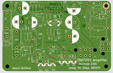
Xmas Amp - Dibya's TDA7293 by Jhofland

Hi Folks,
Members Dibya and Jhofland have designed a new amp using the TDA7293 chip amp. I have not heard it myself, but I trust Dibya's ears when he says it sounds exceptional.

Dibya said that despite this chipamp sounding so womderful, it was surprising that there is not already an existing design on DIYA. So we teamed up with Jhofland who did the design and layout of a mono amp. Jhofland added a DC servo to control the offset and provided some regulated power for the opamp. The board is pretty compact and I am sure easy to build. The best part is that it's inexpensive. The full BOM from Mouser (shopping cart below) is only $26 per channel (not including the home made inductor using 18ga magnet wire wrapped 12 times around a AA battery as a mandrel).

Some of the notable mods developed by Dibya and perfected with Jhofland's help include:

  • Reduced gain of 28db for improved sound quality (default is 32dB)
  • Improved feedback optimizations for better LF & HF sound quality
  • DC offset servo for improved LF performance
  • Addition of Thiel Network for improved stability
  • Tweaks for improved HF response
  • Bootstrap mod for improved bass response
  • Optimized values of decoupling caps for best midrange sound quality

The optimizations for the gain, bootstrap, and PSU decoupling were found using a CRO by Dibya. The lower gain setting was found by extensive listening tests.

Recommended PSU would be a 150VA 25v 0v 25v trafo with 15,000uF per rail for mono, or 300VA 25v 0v 25v with 20,000uF per rail for stereo. Note that if on-board DC servo is not used, then up to 35v 0v 35v trafo's can be used for +/-50v rails for the full 100w output power. However, that will require some really big heatsinks. It is much better to run no higher than +/-40v per Dibya's recommendation. Some recommendations for affordable trafos and heatsinks here.

Note that if populating the DC servo, C17 and C2 should be replaced with jumpers. The on-board voltage regulators are +/-40v max rails so please keep that in mind when choosing the PSU.

The design is free for your personal use and the Gerbers, BOM and schematics are below. Jhofland's designs are superb and I have enjoyed many of his creations. I have not yet built the verification board yet (still waiting for PCBs to arrive) so at this point, you would be building it at your own risk as a beta tester. However, it is quite a simple design and mostly follows the factory datasheet except for the DC offset servo.

If you don't want to order boards for yourself, I can provide them for cost of shipping. First come first serve 25 pairs of boards maximum. Please add your name to the free board interest list below and once we verify they work, I can order boards and get them out to you. This is a holiday special offer that will end by Jan 31, 2021. Boards will be 2oz copper HASL finish with green solder mask.

Special thanks to Jhofland for the wonerful design and layout, and to Dibya for the inspiration and for putting us on this path to inexpensive yet great sound.

Happy holidays and enjoy!
:santa:

Closeup of pdf schematic, main amp portion (note that R15 should be replaced by 47k or as low as 10k to get better zero DC offset tracking and C1 should be closer to 4.7uF to get the deepest bass extension):
904725d1608921278-xmas-amp-dibyas-tda7293-jhofland-tda7293-amp-rev1-1-schematic-main-amp-jpg


Closeup of pdf schematic, opamp PSU portion:
904726d1608921278-xmas-amp-dibyas-tda7293-jhofland-tda7293-amp-rev1-1-schematic-opamp-psu-jpg


Output stage topology from datasheet. Note that it looks like a quasi-complementary topology, could this be the secret to the great sound?:
904727d1608921278-xmas-amp-dibyas-tda7293-jhofland-tda7293-datasheet-output-stage-detail-jpg


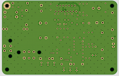
PCB renders:
904728d1608921278-xmas-amp-dibyas-tda7293-jhofland-tda7293-rev2-render-top-png


904732d1608921829-xmas-amp-dibyas-tda7293-jhofland-tda7293-rev2-render-bottom-png


Mouser Shopping Cart:
Mouser Electronics

#### TDA7293 Xmas Amp Free PCB Interest List (maximum 2 boards please) ####

for example:

Name / Country
-----------------------------
xrk971 / USA

Here is the thread for handling the logistics of the giveaway.
https://www.diyaudio.com/forums/swa...3-xmas-amp-jhofland-giveaway.html#post6487628


Edit Jan. 13, 2021: Final design files (Gerbers, Schematic, BOM) are here.

Edit Feb 13, 2021 - cleaned up the grounding on the measurement and here is 10W case, THD is 0.0014%:
922086d1613269769-xmas-amp-dibyas-tda7293-jhofland-tda7293-10-0vrms-crc-10ohms-fft-jpg


Here is 40W case, THD is 0.005%:
922087d1613270322-xmas-amp-dibyas-tda7293-jhofland-tda7293-20-0vrms-10ohms-fft-jpg


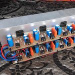
My implementation using surplus Dell CPU coolers:
919834d1612715079-ready-run-rtr-ssr-dc-speaker-protection-delay-gb-b37b96fb-d787-48c7-b1cd-b2618eb956e0-jpeg

Attachments

  • TDA7293_ Schematic_12_06_20.pdf
    TDA7293_ Schematic_12_06_20.pdf
    69.3 KB · Views: 1,090
  • TDA7293-Amp-Rev1.1-Schematic-main-amp.jpg
    TDA7293-Amp-Rev1.1-Schematic-main-amp.jpg
    139.5 KB · Views: 18,217
  • TDA7293-Amp-Rev1.1-Schematic-opamp-psu.jpg
    TDA7293-Amp-Rev1.1-Schematic-opamp-psu.jpg
    110.8 KB · Views: 12,335
  • TDA7293-datasheet-output-stage-detail.jpg
    TDA7293-datasheet-output-stage-detail.jpg
    92.3 KB · Views: 11,986
  • TDA7293-Rev2-Render-Top.png
    TDA7293-Rev2-Render-Top.png
    547.6 KB · Views: 14,176
  • TDA7293_amp_BOM_Dec6_2020.zip
    TDA7293_amp_BOM_Dec6_2020.zip
    5.8 KB · Views: 690
  • Gerbers_TDA7293_ver1_12_06_20.zip
    Gerbers_TDA7293_ver1_12_06_20.zip
    207.5 KB · Views: 693
  • TDA7293-Rev2-Render-Bottom.png
    TDA7293-Rev2-Render-Bottom.png
    323.3 KB · Views: 11,643
  • Dibya-8ch-TDA7293.jpg
    Dibya-8ch-TDA7293.jpg
    193.3 KB · Views: 2,619

Left speaker channel is dead, Topping MX3

Hello everyone! I thought you might be able to help me to do a DIY repair 🙂

So, i have a Topping Mx3 that has been lovely in my garden house. Didn't think of bring it indoor during winter. The problem is most certain caused by condensation or too cold temperatures. Have opened the amp and had it indoor for more than a month. Cleaned the circuit board with Isopropanol, but the problem persists

Where do I start to troubleshoot the board? All tips a welcome!

Symptom when I connect the speakers:
  • Left + and Left -. Dead silent.
  • Right + and Right -, Sound
  • Left + Right -, Sound.
  • Right + Left -, Sound
When I meassure:
Left + and -, around 10 k ohm.

Right + and -, around 10 k ohm.

Attachments

  • left-speaker-channel-is-dead-v0-vikmxub5d2me1.webp
    left-speaker-channel-is-dead-v0-vikmxub5d2me1.webp
    214.2 KB · Views: 46
  • left-speaker-channel-is-dead-v0-n9ojxvb5d2me1.webp
    left-speaker-channel-is-dead-v0-n9ojxvb5d2me1.webp
    57.6 KB · Views: 43
  • left-speaker-channel-is-dead-v0-6h7h1vb5d2me1.webp
    left-speaker-channel-is-dead-v0-6h7h1vb5d2me1.webp
    304.8 KB · Views: 40
  • PXL_20250326_193426655.LONG_EXPOSURE-01.COVER.jpg
    PXL_20250326_193426655.LONG_EXPOSURE-01.COVER.jpg
    576.5 KB · Views: 45

TH-18 Flat to 35hz! (Xoc1's design)

I just got my 18sound drivers from loudspeakersplus.com....ordered tuesday morning had them by friday evening! They are beasts!
photo15nh.jpg


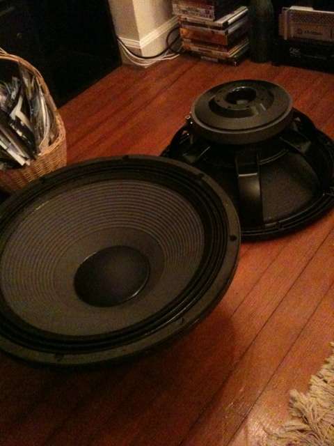
(2) 18lw2400's which will be used in two TH-18 tapped horns, design courtesy of Xoc1 (Thanks again for all the info/effort you put into this!!) Also thanks to Djim for his help and patience through my questions with the design/corner bracing etc etc.

This thread is for anyone who builds his box. I figured I would start because I think I am one of the first to do so!

I will go pick up some good high quality 3/4" Birch tomorrow and get started on this. Pictures to follow asap!!

Here is the Sketch plus a nice cut list...
View attachment TH18 + CUT LIST.PDF

223205d1305579189-c-e-x-pa-flat-30-ft30-pa-th-awesomeness-th18-additional-corners.jpg


Extra bracing which Djim suggested...
An externally hosted image should be here but it was not working when we last tested it.


Now I am pretty sure that the point of this design was for 4 cabinets to be Flat to 35hz. I am starting with only two because of cost, not just for drivers/wood but amp power needed to drive them as well. These are some powerful cabinets and depending on which driver you choose to load them with, they can take a serious amount of wattage!

There are a ton of different drivers which have been simmed for this design, I think most have been simmed for the cabinet without the corner reflectors, but still the same external volume cabinet.

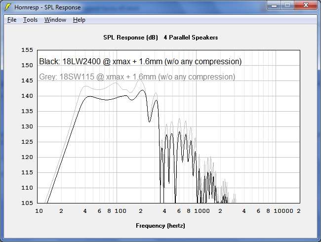
Here is a sim for 4 cabs at xmax + with the 18 sound 2400 drivers...
spl418lw2400vs18sw115.jpg
  • Like
Reactions: stewin

Power amp measurement system

I decided to upgrade my poweramp measurement system.

The devices:

1/ ultra low distortion sine wave oscillator - I bought Victor's 1k and 10k
2/ dummy load - designed and made by me
3/ passive voltage divider - under development
4/ passive notch filter- schematic Victor, made by me
5/ post notch buffer - under development - powered by two 9V battery
6/ PC sound cards I have
- ESI Juli@ PCI
- Asus Xonar STX II
- X-Fi USB HD modded Improving A/D perfromance of Sound Balster X-fi Music (SB1240) - and a Puzzle!!! - diyAudio

attachment.php


the dummy load

Attachments

  • DUMMY LOAD LKA.JPG
    DUMMY LOAD LKA.JPG
    51.2 KB · Views: 437
  • dummy_load_1.jpg
    dummy_load_1.jpg
    324.3 KB · Views: 491
  • dummy_load_2.jpg
    dummy_load_2.jpg
    253.4 KB · Views: 399
  • dummy_load_3.jpg
    dummy_load_3.jpg
    134.8 KB · Views: 287
  • dummy_load_4.jpg
    dummy_load_4.jpg
    264.1 KB · Views: 295

Suggestion for bass assisting woofer

I have a pair of 4" phillips full rangers (will be replaced in future) that distort anytime any heavy bass is played . So I have been looking to build a either a pair of speakers that specifically play the lower end or a dedicated subwoofer. Moderate spl about 85-95 db not looking to go too low ; room is 270 sq ft and my budget is $150 usd. Wavecor, SB audience/acoustics, some Dayton and faital woofers are available in local market.
Any suggestions would be helpful and btw it is meant for a home theatre.

I will sell various sockets for radio tubes ceramics - carbolite

I will sell various sockets for radio tubes ceramics - carbolite

payment paypal
possible exchange for radio tubes

1) 11pin relay panels 24 pieces used for $1 each

2) Magnovall panels for EL509\E55L
2 not used 19 pieces used for $20 all

3) LOCTAL panels (4P1L\7N7\EBL21)
ceramics in a cage with metal ears 4 pieces used for $2 each
carbolite in a cage with metal ears 1 used 2 new $6 all
carbolite with metal bracket Germany new 2 pieces $3 all
ceramics lamellas 8 new 2 used $15 all

4) EF86\12ax7\6n2p\EL84 open new
30 pieces with long legs $30 all

5) Panels ceramics GU50\GU15
5 pieces ceramics 1carbolite $7 all

6)
Caps 8 pieces from TVS
Caps 5 pieces closed 6f5\ef37\6j7
Caps 36 pieces open various 6f5\ef37\6j7
12$ all


7)
Caps 807 tube carbolite\plastic 6 pieces 6$ all
Caps 811 tube open 6 pieces 8$ all


8)
panel 845\211 lamp ceramics 15$
Panels ceramics for 813\4E27\6A6\gu13
RCA UT-104 new 12$
JOHNSON 237 used 10$
6с33с panels thick crimping 2 closed one open 16$piece
good quality


9)
octal 8pin panels ceramics
round panels with good contacts 23pieces used -110$ all


10)
octal 8pin panels made of textolite
22 panels new and used 30$ all


11)
LOCTAL 9pin panels (EF50\EF54)
thick ceramics with British ears 2pieces used
ceramics with ears 3 pieces 160 UAH used
solid ceramics 1 piece used
30$ all

panels 5pin AKORN (957\955\954)
ceramics 8 pieces 15$ all


12)
Panels for RV12P2000 used 3 pieces -10$ piece
panel for RV12D60 1 piece -10$

Panels for Y8 EL11\EL12\EF12 carbolite
7 pieces round Germany -8$ piece
3 pieces oval Germany -8$ piece one glu


13)
panels g807\56 UX5
used textolite panels использованные 3 pieces $2 piece
carbolite panels used 1 piece $2
solid ceramic panels with ears used 1 piece $8
ceramic panels without rings used 3 pieces $6 all

panels 2A3 carbolite UX4 without rings 2 pieces $4 all

panels 6A6\53\310A carbolite UX6 without rings 2 pieces $6 all


14)
panels for GK-71
carbolite collet 3 pieces $15 all
textolite paired panel with holders $8


15)
panel 12s3s\LD1 one with screen $10 pair

Panels for spider AL4\EL3\AF7 carbolite
new 8 pieces -40$ all
soldered 1pc -3$
soldered 1pc adapter EL3\EL6-> 6L6 -3$
Germany original for 3 ears used 2pcs 20$ pair


16)
octal 8pin panels made of carbolite with a nut
black panels mount nut 10pcs - 2$ each

octal 8pin panels made of carbolite with ears Germany
12pcs B\U and new -50$ all


17)
octal 8pin panels made of carbolite with ears
23 panels used - 2$ each


18)
octal 8pin panels made of black carbolite
with metal clip and ears used - 19pcs 2$ each
with metal clip and ears used collet 1pc -10$
mounting panel USA used 1 piece 5$


19)
Octal 8-pin panels made of brown carbolite with metal ears
in a metal clip 20 pieces used 4$ each


20)
Octal 8pin panels made of carbolite
under a bracket with two screws - without a bracket used
good quality contacts 12 pieces 6$ all
collet carbolite panel with crimping 1 piece 10$

collet ceramic panel with crimping 1 piece 10$
2A3 panel ceramic new gold 30$ pair

20250319_160544.jpg
20250319_161257.jpg
20250319_171047.jpg
20250319_172037.jpg
20250319_172552.jpg
20250319_195538.jpg
20250319_200508.jpg
20250319_203056.jpg
20250319_205334.jpg
20250320_111347.jpg
20250320_112313.jpg
20250320_133437.jpg
20250320_134534.jpg
20250320_150713.jpg
20250320_162852.jpg
20250320_180500.jpg
20250320_185417.jpg
20250319_145311.jpg
20250319_153147.jpg
20250319_154648.jpg

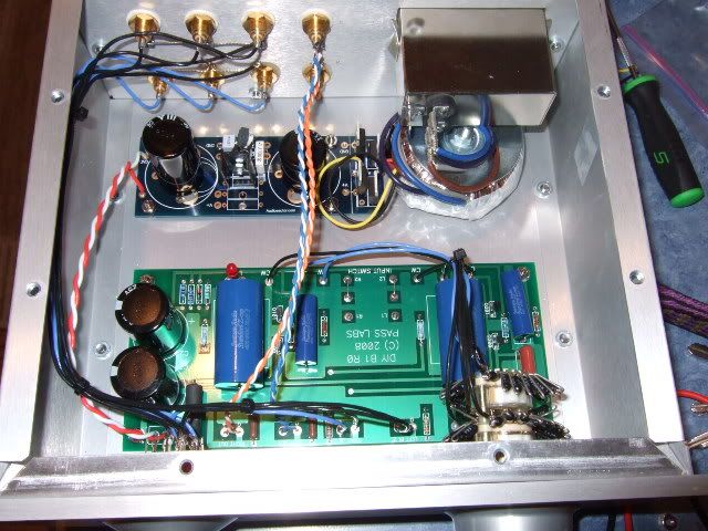
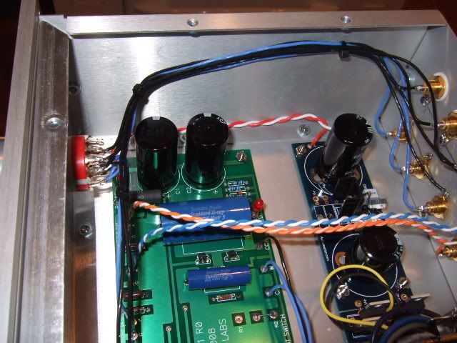
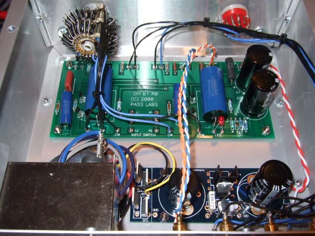
B1 preamp build thread

Hello!

I recently inherited a bunch of stuff from a fellow DIYer, and one of the things was a nice chassis suitable for a preamp or perhaps Chipamp with an outboard PSU. Discussions with other members, as well as a healthy dose of curiosity led me to choose the B1. It went together very easily and quickly. Here is the log of that build.

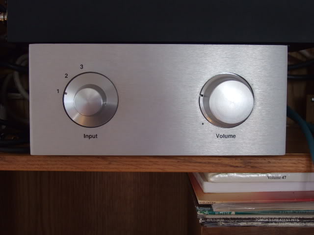
The finished product. It sounds fantastic!
244962d1318790367-b1-preamp-build-thread-dscf3556.jpg


But how did I get there? well...

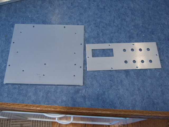
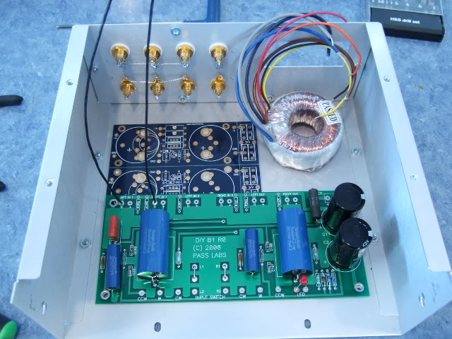
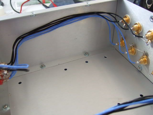
When doing a project like this, the easiest place to begin (for me, anyway...) is the mechanical. Drilling, hardware, things that touch the chassis. Not a lot of drilling was involved, the power inlet module was pre-cut, so I added the holes for the RCA jacks and the screws for the circuit boards and transformer.
244960d1318790367-b1-preamp-build-thread-dscf3528.jpg


This is just placing the various boards and transformer in place to see how things will fit. The blue board shown in this photo is actually a dual-rail PSU PSB from Peter Daniel, the single rail is exactly half of it.
244961d1318790367-b1-preamp-build-thread-dscf3532.jpg


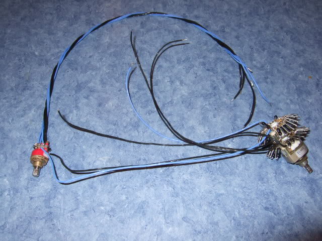
This is a really nice Goldpoint switch and series stepped attenuator made from a Elna 24 pole switch and a bunch of Holco resistors. It's all wired up because it was salvaged from a different project.
244966d1318790688-b1-preamp-build-thread-dscf3529.jpg


You will notice in this photo that the grounds of the inputs are wired together. This is for two reasons... firstly, the RCA jacks all float on the chassis - the shoulder washers isolate the jack from the chassis. Also, the PassDIY circuit board has a pad for ground on both left and right... so there will be wire connected to one of these negative tabs to the PCB pad.
244967d1318790688-b1-preamp-build-thread-dscf3531.jpg


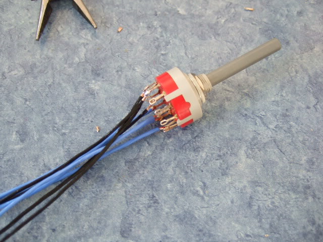
A well-stocked junk box to the rescue!! This switch is the one I had to use in the end... the Goldpoint that was on the harness with the attenuator had a shaft that was just too short to use with the knobs on the chassis. This switch was bought only a few weeks ago as I was perusing through the local surplus store and saw this switch perfect for a preamp. Luck favors the prepared!
244968d1318790688-b1-preamp-build-thread-dscf3535.jpg


DSCF3536.jpg

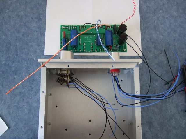
So here are the selector and the attenuator mounted, and the PCB with some of the wires soldered in place. In order to keep the wires as short as comfortable, it is prudent to solder all of one edge in place, and then you only have to do the other edge in place. if you do this, make sure that your wires are at least a couple of inches longer than you know you will need. Too long you can trim, but too short is a pain in the backside!

DSCF3537.jpg

The wiring continues.

DSCF3540.jpg

I originally envisioned the preamp board turned the other way, to keep the leads from the RCA jacks shorter. The size of the attenuator happened to get in the way of the black electrolytic caps, so it got turned 180deg.

DSCF3548.jpg

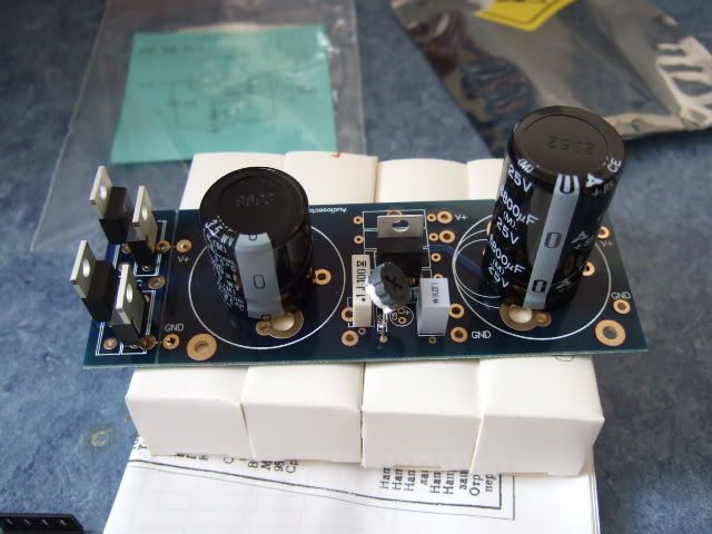
Here is the single-rail universal power supply PCB from Peter Daniel. It's a very nice board, with the ability to choose 2- or 3- pin diodes (or none at all), many different lead spacings on the filter capacitors, and either a LT1085 or LM317 regulator. Shown here are MUR860 diodes and a LM317 regulator.

When I first fired this up I couldn't adjust it to get more than about 7.5-8 volts on the outputs... I was slightly confused, and knowing that just thinking about it wouldn't fix anything, decided to measure the components... It turned out that I grabbed a 240K ohm resistor when I need a 240R... 😀 Anyway, I didn't have anything close to 240, but I happened to have two 150R that are now placed in series in that position, and it works very well now! The range of adjustment is about 17-25 volts, and have it set at 19.5v

DSCF3549.jpg

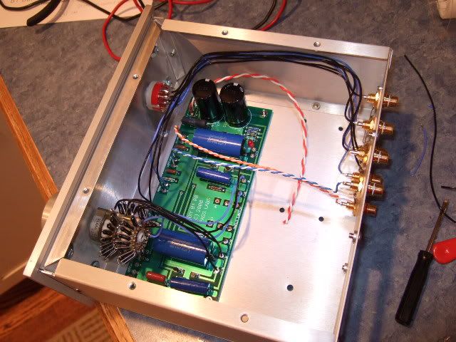
This is the last check of the wiring to see where the power supply wires will place.

Just to recap, the black and blue are signal input, switching and attenuation, the red/white is from psu board to preamp board, and the blue/blue-white, orange/orange-white is the output.

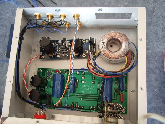
DSCF3550.jpg


And here it is complete - the power inlet module is installed and above the transformer, the yellow/black leads are the secondary of the transformer.

DSCF3553.jpg


DSCF3552.jpg


This was a very easy and rewarding project. I cannot express enough gratitude to both Nelson Pass (you rock!) and Peter Daniels (you also rock!) for making the circuit and and the PSU board. Although something like this could be very easily made on perfboard (and I thought quite seriously about it) any project is greatly simplified by good circuit boards!

Attachments

  • DSCF3528.jpg
    DSCF3528.jpg
    47.5 KB · Views: 24,504
  • DSCF3532.jpg
    DSCF3532.jpg
    70.1 KB · Views: 24,992
  • DSCF3556.jpg
    DSCF3556.jpg
    29.7 KB · Views: 24,798
  • DSCF3529.jpg
    DSCF3529.jpg
    70.8 KB · Views: 24,595
  • DSCF3531.jpg
    DSCF3531.jpg
    61.6 KB · Views: 24,447
  • DSCF3535.jpg
    DSCF3535.jpg
    69.8 KB · Views: 22,263
  • Like
Reactions: audiosteve

  • Locked
For Sale 2pcs UNI-T 61E+ with hFE adapter for TH and SMD

Here i have new UNI-T UT61E+, 22000 Counts with high DC and AC precision and large display backlight. It comes with adapter that you plug in into multimeter socket and then you can meausure and match transistors, diodes, led in throught hole and smd package.

It is uniqe design because todays multimeters does not have hfe function.

With this multimeter you can match transistors for any amplifier and preamplifier project.

Comes with nice original uni-t silicon leads that are flexibile and high current (20A max).

Price is €110,00 plus shipping for 1pcs. Payment via IBAN or paypal.

I have 2pcs in original box for sale.

Here is pictures of this nice multimeter.

Attachments

  • IMG_20240915_192406.jpg
    IMG_20240915_192406.jpg
    400.3 KB · Views: 177
  • IMG_20240915_192442.jpg
    IMG_20240915_192442.jpg
    368.5 KB · Views: 165
  • IMG_20240915_192558.jpg
    IMG_20240915_192558.jpg
    303.2 KB · Views: 166
  • IMG_20240915_192614.jpg
    IMG_20240915_192614.jpg
    251.1 KB · Views: 172
  • 1670535120084-min.jpg
    1670535120084-min.jpg
    374.2 KB · Views: 175

For Sale Revox B790

I have a Revox B790 turntable with Ortofon cartridge for sale. It was working when I put it in storage in the original box 20 years ago when I moved onto a boat, but I'm sure by now it has some dried up capacitors that need to be changed. I'm in NY and want $500 + shipping, but I'm sure it would sell for much more after a refurb. Anyone interested?

Discussion: Padding Down Mid/Tweeter VS Multiple Woofer/Mid to match Tweeter

I do not see this discussed to any extent so I'd like to open this up.

As we all know, different drivers have different sensitivities. As far as I can tell there are two solutions to this issue if you plan to design an accurate loudspeaker:

1. Pad down the higher sensitivity drivers to match your lowest sensitivity driver
2. Increase the number of lower sensitivity drivers until they match the higher sensitivity drivers
I see the pro/cons of these options as thus:

Option 1
Pros
1. Cheaper: Less drivers means lower cost
2. Smaller: More compact for space savings
3. Simplicity: Less drivers means the design and the response is simpler. It is easier to take measurements.
Cons
1. Loss of sensitivity: Your system sensitivity will only be as high as your lowest driver
2. Potential cost of amplifier: You will need so spend more on your amplifier as your system will be harder to drive
3. Less amplifier options: Depending on your final sensitivity, you selection of amplifier may be cut down significantly
4. Less woofer/mid options if you need a higher sensitivity system

Option 2
Pros
1. Higher sensitivity: you would be able to use whatever amplifier you wanted with a high sensitivity system
2. Driver work: The amount of work the lower drivers will have to perform will but significantly cut down. Your woofers will handle much more power before hitting XMAX
3. Power threshold: The system should be able to handle a lot more power before distortion
4. Less amplifier distortion, less woofer distortion
5. With more driver in vertical axis you should be able to significantly reduce vertical cancellations which should better fill a room
6. It will look super impressive: No doubt, a loudspeaker using redundant drivers that goes up to the ceiling looks far more impressive.
7. You can use any woofers you want as sensitivity can be accounted for using multiple drivers.

Cons
1. Much more expensive: You will need multiple drivers, however, your crossover costs should remain the same
2. More complex build: The enclosure will be much more complex to design and build
3. More complex measurements: I have not personally ever measured redundant drivers but I imagine it isn't as cut and dry as measuring just one.
4. It will take up more space: It is going to be much larger. Geometry is geometry.

I'd like to hear all of your thoughts on these two different approaches as I am considering using multiple drivers to up my sensitivity on my next build. I have an example below that is really a hybrid of the two

I will also throw into this mix a discussion of low frequency sensitivity. Most of us are trying to boost the low frequencies using multiple drivers. Tweeters play loudly, woofers do not. I have heard that what matters most for the low end is cone area and power. The driver sensitivity doesn't matter below 150 hz or so. I do not know if this is true. It does not seem like it is true. Then again, I do not know exactly how sensitivity is measured. I hear it is playing a 1000hz tone with 1 watt then measuring the decibels. Due to peaks, cone resonances, and driver frequency response I would think this would not be a perfectly accurate measurement for all drivers. If someone knows, please post that information as I feel it is critical to this discussion.

Please ignore any errors on this XO and design. It is just an example for flare that I tossed together in a hurry.
1743174258309.png

Help with repairing a Memphis Audio PR1x1000? How to check the transformer, is it shorted?

Hello, I am currently trying to repair a Memphis Audio Pr1x1000 amp. I think I have narrowed down the problem to a short somewhere near the transformer, (I think). And I am trying to rule out the transformer as the problem, but I dont exactly know how to test the transformer, I am getting a couple of shorts on the transformer, but I dont know if that is normal or not, I can leave a photo of what is shorted together. Can someone help me figure out what should, and shouldnt be "shorted" on the transformer?

Some things I have done:
I thought it might be a mosfet/transistor, but I pulled all the transistors, and the short was still there, and all the transistors seem to be in working condition, (from what I can tell)

I used some IPA around the board to check for hot spots, and two diodes and a small capacitor were getting hot when the amp was powered on, so I pulled them, and the transformer seems to be shorted still, unless what Im seeing continuity on is normal. (You should be able to see the diodes in the photo, they are the ones slightly askew as I put them back on the board)

I also found an IC that was getting warm, a IRS2092S (op amp?) but when I pulled it, the transformer still has those "shorts"

I tried hooking my multimeter in continuity mode to the "shorts" on the transformer, and wiggling wires to see if it would stop or change, but it didnt

Idk, but at this point im lost, and just wondering how to make sure my transformer is good, or what else I should be checking.

Any help is much appreciated.

Transformer1.png

Repair of burned Voice Coils for Vintage Loudspeaker Chassis/Driver - which Companies ? - Overview wanted

There are a lot of companies, which replace surround foam or rubber. But companies for remake voice coils are rare,. because this is much more difficult.
An overview of such guys around the world would be helpful in any cases.
E. g. for Foval's kevlar drivers under
Thank you for posting addresses of such companies.

Noisy NAD 7240PE - how to diagnose issue?

Hi everyone - So I have this NAD 7240PE. It's an absolute beast of a receiver that I bought sight unseen from the other side of the country and it arrived pretty beat up. It was super dirty and dusty inside and noisy as hell and the seller proceeded to never return any of my messages 😅. Several of the largest caps had burst at some point and spilled their goop on the PCB, which itself has turned brown from heat in the amp section, it must have been run HOT a lot. The radio tuner side meanwhile is still green as a normal PCB and works pretty well even just using the built in FM antenna.

I switched out the busted caps and cleaned it up and it's working a lot better but there must still be some component(s) fried or something since the amp has a ca. 10 sec period at startup and turn off where it plays this kind of ground saw wave noise through the speakers similar to touching an input jack your finger. After that stops, there is still this random, intermittent popping sound in both channels underneath the audio signal but it decreases slowly until - when the amp is warmed up perhaps - the noise is gone. At this point, the amp works almost noiselessly and sounds absolutely superb.

I'm telling you, the combination of buttons called “Bass EQ” and “Loudness” really make this amp drive way more nice low-end from my two Artcoustic wall mounted speakers than my other, newer NAD C316BEE ever could. It also sounds much more dynamic and enjoyable, no doubt partly due to the pretty complex BJT-based Class G topology in which separate higher voltage power rails are switched to momentarily when triggered by a powerful enough input signal, ultimately resulting in higher efficiency and dynamic range I believe.

Anyway, in my search for knowledge that could help in diagnosing and fixing the issue, I came upon some 7240PE repair threads on here and some people (e.g. Mooley) seem to have the skillset and experience needed to diagnose this kind of stuff so here I am, asking for some tips on what to look into on this amp 🙂

I can record the noises in question if it helps, as well as measure anything with a multimeter. I also have a power supply and even an old analog Agilent Oscilloscope that I bought cheap from my old student job employer (ICEPower) as they had stopped using it in favor of the new digital ones. It has been sitting in a cabinet unused since because I have yet to buy some probes for it - which I will if it will help fix this amp!

P.S. Here's the service manual which includes the amp schematic on page 13 and here's also some technical info on how the Class G voltage switching works for those interested:

Screenshot 2021-09-22 105305.jpg

Rega P8 or P10

Hi everyone, I have recently bought an old banged up Rega P2 and was hoping to try a new build.

I thought it might be good to try a P8 (P10) clone, with the new shape base and a rewired / silver RB250 arm.

I have details of how to remove the black paint from the arm and a template to drill holes in the arm and rewire. What I don't have is a detailed size / cutting shape for the base.

Is there anyone who could help me with this please?

Thanks

Geordie

Do LED bulbs cause interference on audio circuits?

I am in the process of setting up an amateur recording studio in my workshop which has overhead fluorescent light fixtures. I am changing the fluorescent lights to incandescent fixtures due to the tendency of fluorescents to cause interference noise in audio circuits, which in my case will be both line-level and microphone-level.


I had not shopped for incandescent light bulbs for some time, so when I went to the home improvement store to buy both the fixtures and the light bulbs I was somewhat dismayed to discover that LED bulbs had almost completely supplanted incandescents on the store shelves. I asked the sales clerk about them and he said that each LED bulb has a transformer integrated in the bulb chassis. Having no experience with LEDs I don't know if they can cause noise in audio circuits, so I am hoping that some members with more knowledge than I have can clue me in.


For now, I have stocked up on some halogen incandescent bulbs, but for future reference I would like to know the story on LEDs. The sales clerk told me that the store will stock incandescents for the forseeable future, but having witnessed the rise and apparent fall of CFLs and the vagaries of the relevant governmental agencies I am without faith in such pronouncements.


So, what's the real story? Has anyone experienced LED-induced noise in their audio circuits, and is there any reason to expect that they could cause such interference?

ES9039Q2M output stage?

This is the (v2 = improved) output stage from the ESS data sheet:
1721936262265.png
I understand that thevalues of the components around the op amp are no longer critical to avoid the hump, and no published data of 9039 DACs that I have seen exhibit the hump.

Does anyone know what the three op-amp version with slightly improved THD+N looks like? I the third op-amp maybe just for buffering the reference voltage, as a symmetrical output should have an even number of amps?

Is there a simpler way to get unbalanced output? Just using one side of the symmetrical output signal seems odd. The Chinese 9039 board seems to use only one op-amp per channel.

Steve Benchs no C RIAA

Has anyone an idea how to calculate the R9 adjustment for using an LL1660 instead of the LL1623?

Steve says:
"Note that ther are no capacitors in the signal path. In the early phase of design I had intended the LL1623 (a large output transformer) to be used as the interstage transformer. Unfortunately, there was too much variation in inductance with signal level, and the frequency response varied with level. Placing the 1660 as IT cured that. The reason for the 1623 at all was to take advantage of the low winding resistance. O well. I suspect 1660s can be used for both transformers, but R9 will probably need to be adjusted for proper RIAA compensation (due to the added transformer resistance). "

Attachments

  • LR 1660.jpg
    LR 1660.jpg
    60.5 KB · Views: 183

IanCanada or??

Hi,

I currently don't have any DAC in my system and all the streaming goes via the PS5 console. Pulling the audio signal off of the HDMI out cable via splitter and feeding it into the preamp. Most of you will agree it's very far from the ideal setup lol.

As I'm always leaning towards DIY solutions, I came accross IanCanada stuff, and ofcourse, the million dollar question pops. Is it worth it?

For the flagship DAC with all the transport and needed bits and bobs, it adds up to about $800 USD. Then the PSU, chassis, raspberry pi board and we're arround $1500.

The cool thing I see with the whole thing is the "platform flexibility", as everything is running on the raspberry pi and me being an IT guy (linux prefered), everything looks even more apealing.

The part I'm strugling to find more info about is how does it compare to other DACs in the same price range, around $1.5k?

Is it worth the money, from the audio perspective?

Or should I go with some brand name DAC, or even a Wiim Ultra which apparently everyone love so much, and just call it a day?

It would be a fun project to build something like that, but not sure if it's worth the money. I plan to use it mostly as a streamer, as it's main purpose is anyway.

Please let me know your thoughts and comments, and please suggest some alternatives if possible. As allways, much appreciated and thank you!

Cheers!

Speakers (Altec 604?) inside built-in cabinets?

Hey everyone,

I moved back into my childhood home recently and I'm also getting back into audio after being away from it for a few years. My late father made some built-in cabinets with a fireplace in the living room as seen in the attached photo. Since my old man built them I don't want to alter them too much, but the cabinets and the position of the couch, which really can't go anywhere else, make speaker placement difficult.

As you can see in the photo, there are two large cupboards on both ends of the built-ins. The space inside is about 38" wide, 35" high, and 20" deep. So I've been wondering if I could put some speakers inside those cabinets, rather than on the floor in front like I'm doing now. I have a pair of JBL L166s now that I may experiment with, but I'm wondering if something even bigger might make better use of the space available.

I have a chance to buy some Altec Lansing 604-8k speakers in 620 cabinets at a reasonable price and I'm wondering if they might work. The 620 cabinets are too tall, but they would fit if I remove some trim around the cupboard doors. I'm also a pretty good woodworker and could easily build some smaller cabinets that would slide into the space available. I could replace the doors with custom grills too.

Does this sound like a good idea, or am I crazy for even thinking about it?

Any feedback would be much appreciated.

Thanks,

Andy

living-room-cabinets.jpeg

A

How to connect QUAD 33 to 2×303s (Vintage)

Hello everyone, I've recently bought the quad 33 and 2 of the 303 power amplifiers. Since the 303 do not have an on/off switch do thay permanently stay on?

Thay are connected via a 4pin din into 33 which is then split into 2 4pin din for each 303. Power is a 3pin din into the 33. One 303 has a 3pin din power and the other has a kettle lead 3pin power cable. Is this correct.

Advice needed on how to connect/use as mono blocks.

Tube preamplifier diodes replacement

Hello guys

I have a tube pre witch is i think an mu stage cathode follower. It uses 1 x 12au7 and 1x 12at7 each channel. Its a complete dual mono design with 2 independent PSU in a separate box. In the psu for EACH CHANNEL we have 2 separate toroidal one for high voltages and one for the low voltages. The voltages are a b+ 217v at 120 mA , a 12v at 1A all DC regulated and 6.3v AC. The b+ is regulated by an ECL82 tube thats why we have the 6.3v ac for the heaters of ECL82 to operate.

My question is...

At the b+ we have 4 diodes IN4007 and then the ecl82 for regulation with the caps resistors an all the needed parts for the application.

At the filaments section we have 4 diodes IN4004 then a 7812 regulator and all again the needed parts as above. The filaments are in series 12v dc

The 6.3 is ac direct to the ECL82

Can i safely replace all the 8 diodes in each channel psu with the VISAY uf4007 or i am going to start a nuclear disaster 💣here?

Value of old paper capacitor by color codes?

I'd like to replace this old capacitor, but before clipping it out to measure it, could anyone help me figure out the value by the color code?
One problem is that I don't know which end of the capacitor has the 'first' color band. Does it start with green? Or does it start with blue?

1727091348485.png


Is the thicker green band the voltage indicator? If so, I guess that means 600V (DC).
After that, I get:

Grey = 8
Orange = 3
White = 9

And for tolerance,
Blue = 6%

That doesn't make sense to me. I must be reading this wrong. Can anyone help me understand how the manufacturers color coded these old capacitors? Thanks...

Fully balanced MC phono preamplifier thoughts

Dears,
This is sub-thread of my turntable post: https://www.diyaudio.com/community/...eded-with-motor-and-drive.412984/post-7687982
It seems appropriate to open new one just for the preamplifier.
Since I'm waiting for motor parts to start significant upgrade of this 22 y.o. thing, I will revisit the preamp too.

So far I was using this design with 2 x SSM2017 in first stage and 2 different second stages, description is here: https://www.diyaudio.com/community/...eded-with-motor-and-drive.412984/post-7688045

For the new version, I have 3 personal preferences that I would like to respect:
  • Fully differential, I see great benefit and improvement from dropping ground of the signal path. Even still I'm using GND for referencing output voltage, but in new design I'm considering bootstrapping that with very low noise amplifier.
  • Passive RIAA EQ
  • As high as possible first gain stage, 60db (1000 V/V) seems just fine with my 0,34 mV nominal output cartridge. I do use higher PS voltage to allow for more output possibility; now +-18, next +-20V. This leaves second stage to deal with only about 20db gain.
Right now I'm making upgraded PCB with same concept, SSM2017 remain as input, second stage upgraded to OPA828.
SSm2017 specifies 0.012% THD+N at gain of 1000, I probably get it bit better as 2 amps in differential configuration will cancel some distortion. However not the best in class THD, nevertheless doubt if it is hear-able. Nevertheless SSM2017 as ancient as it is, is still unbeatable on noise performance.
Here is PCB work in progress:
1720256678366.png


Alternatives (in my thoughts) for the first stage :

2nd option is to keep configuration but to upgrade SSM2017 with better INA like AD8429 for instance, as used here https://www.diyaudio.com/community/threads/chipomatic-balanced-input-riaa.331009/post-5627780 (but this is single ended output)

3rd option is classic differential receiver (same as my second stage now) , but that would call for 4 x AD797 and cost of over 70 Euro, I see no other opamp that would fit this purpose.
1720257443572.jpeg


4th option is to use this ancient schematics and replace each AD797 with it in above schematics. Probably that is as far as low noise is possible.
Matched low noise dual transistors are rare today, but there are many dual JFET's that would do just fine here. Of course some more modern opamp would be used instead of OP27. However, this design for stereo would call for 12 dual matched low noise transistors, quite heavy on wallet.

1720258101394.jpeg


Or, 5th idea, this very fine simple circuit from John Broskie's site. Looks very tempting even the gain will be max 40db (x100), so second stage will need to deal with another 40db, but that is not major issue if below circuit is quiet enough.
1720258822196.png


I'm sure that each of these options will work just nicely (when fully developed), but what would be the best?
Any comments, thoughts, ideas?

Polk PSW10 drawing inward on hits

Hello thread goers, i need some help figuring out why my subwoofer is drawing inwards during and after hits of bass. If there is a part where the sub hits and holds a frequency between 30-60hz, the sub kinda recedes into the enclosure. not sure if it’s an optical illusion or if it’s supposed to happen but i just wanted an answer. thanks
video of it happening

How to calculate heating of Diodes

Hello everyone,

I have 4 diodes creating a full wave bridge, and am replacing some old diodes that I have been told look they are getting a little hot.

They work for a DC heater on 211 valves. The heater is at 10.5AC and 10V, 3.25A after rectification.

Is there any way to look at Diode specification sheets and determine temp performance, they are DO-247 format.

Rich

Your best record pre rack

Hi there! I would create my own record rack and I'm interested in what hardware you need for pre-processing sound when recording. I'll include some of your suggestions in my record rack. The basis is naturally clear: a preamp and an equalizer. In my case, they will most likely be the API 500 series and an equalizer based on the Calrec Pq1549. But I would like to learn about the other components from you) I look forward to your suggestions. Yours, Matthews.

#26 pre amp

Hi All,

I am in the process of completing Phaeton RC 26 preamp published on http://www.vt52.com/ site (Jim de Kort) as my latest DIY project. But still I am little puzzled with few things with my current project. Hope someone could provide an expert advice to me to figure out those.

One thing I am confused with is the hum coming out from B+. I figure out it is something to do with the grounding however. Lately I found out that if I ground the filament negative with B+ negative with 470uf capacitor, the hum is almost disappearing. But not sure whether this method is right or safe because what I did was sheer coincidental . Need advice on this. I used separate power rail using a SMPS for filament and both filaments were connected serially with 3V supply. Only connection for B+ negative from this rail is 470uf negative to negative (capacitor + to filament's negative and capacitor - to B+ negative).

Second thing I am puzzle with is the bias supply. Should I use separate 12 V supply for bias for 26 tube or should I use voltage divider to get the bias supply? Where exactly should I connect the bias voltage in this schematic?

Greatly appreciate if someone could clarify these for me.

An externally hosted image should be here but it was not working when we last tested it.


Added as requested by djn -

Jim de Kort's site
Kevin Kennedy's PF article
Keven Kennedy's Schematic PDF
Where to begin? At the beginning of this thread
Coolzero 1
revintage 1
revintage 2
mach1 sneaks in a 12B4A schematic
Richard's double-fisted 156C choke load
coolzero's hum avoidance diagram
coolzero 2
revintage 3
andyjevans's 10Y preamp
regal's 26 driving 71A
Rod Coleman's DHT linestage
Rod Coleman's DHT linestage with power supply
andyjevans 26 with AZ1 rectifier
coolzero 4
mogliaa's 26 testbed
Original Burnedfingers
euro21
mogliaa's 01A
mogliaa's 26 source follower
dhtrob's 26
andyjevans still can't find the rotate 90° command
Rod Coleman's 26 with a filament-on-filament bias with IDHT output
euro21
mogliaa version 2
Nightpuma's 26
dhtrob 2 (now with grilled pencils)
H.Michi
andyjevans 26 with VR tubes.
andyjevans 26 with VR tubes and CCS

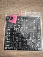
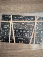
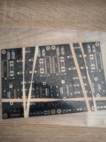
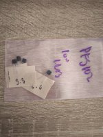
For Sale Salas DCG-3 preamplifier (full kit)

I have for sale 1 complete full kit for new builder. Sales only as a whole, all together.
My offered kit includes:
1, Salas DCG-3 circuit board
2, DCG3 full kit from Tea
3, DCSTB circuit board
4, Salas Mezmerize input selector circuit board
5, LKA AC Power Controler circuit board + ATina
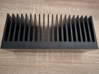
6, GammaAluminium KA200x60 black heatsink
7, TS100VA AUDIO GRADE (240AC, 4x18V)
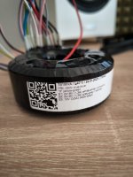
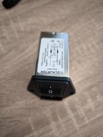
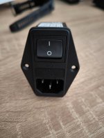
8, AC connector Schurter 4304.4001
9, On Semi PF5102 (low IDSS measured) 4pcs

I paid 320€ for these parts, I offer 15% discount --- 270€ + shipping. I only send within the EU
Paypal or Wire transfer.

Attachments

  • IMG_20250216_122636.jpg
    IMG_20250216_122636.jpg
    354.4 KB · Views: 145
  • IMG_20250216_122644.jpg
    IMG_20250216_122644.jpg
    318.1 KB · Views: 162
  • IMG_20250216_122728.jpg
    IMG_20250216_122728.jpg
    425.5 KB · Views: 157
  • IMG_20250216_122814.jpg
    IMG_20250216_122814.jpg
    194.4 KB · Views: 156
  • IMG_20250216_122820.jpg
    IMG_20250216_122820.jpg
    243.9 KB · Views: 146
  • IMG_20250216_122832.jpg
    IMG_20250216_122832.jpg
    512 KB · Views: 149
  • IMG_20250216_122844.jpg
    IMG_20250216_122844.jpg
    535.3 KB · Views: 150
  • IMG_20250216_122850.jpg
    IMG_20250216_122850.jpg
    500.9 KB · Views: 151
  • IMG_20250216_122908.jpg
    IMG_20250216_122908.jpg
    456.7 KB · Views: 145
  • IMG_20250216_122941.jpg
    IMG_20250216_122941.jpg
    362.9 KB · Views: 145

SBAcosutics membrane/diaphragm question

Hi to Everyone,
i have a very serious question regarding the type of "fabric" membrane of SBAcoustics, such as TW29D or TW29R of the SATORI series against the basic series for example SB29SDAC or SB29RDAC because at first sight they seem identical and if it were so it would be a kind of bluff.

The scan-speak instead uses a type of "fabric" membrane for the discovery series and another for the top series, it is very obvious visually.
Also it even seems to me that the scan-speak membranes of the discovery series are very similar/identical to all the "fabric" membranes of SBAcoustics.

But how is this possible?, does anyone know anything?
Thank you very much.

Audio Innovations Alto amp overheating

I acquired an Alto amp last October, and it has run fine until now, apart from a loud buzz which was tracked down to the volume pot's earthing connection. Loosening the mounting nut stopped that. But now the right channel has started to run away, thermally. I have measured everything I can with a multimeter, comparing left and right channels, and have not managed to find any differences so far. This is unpowered, as I only get 20-30 seconds before the fuse on the left channel blows.
I have an infrared thermometer, so I can run it until it gets to about 30 degrees and then power off. The left channel barely warms. Looking at the instructions, I get half PSU voltage on R21/R22 as I should. I haven't yet checked across R21/R22 for 30mV.
I am fine building amps, but not so hot with fault finding, as I can follow a schematic without fully understanding exactly how it works. Hands better than brain! And I have all the transistors and diodes if I need to replace them. I haven't removed any components yet to fully check them.
What I need is help with understanding which components are the most likely to be causing the problem. I can replace any I need to, I can reflow solder joints, etc.
54407307410_5e7dbc628b_k.jpg

54358872048_761767aef8_k.jpg

54157273101_a3d056938f_c.jpg

The XEN XELF Headphone Buffer

The XEN XELF Headphone & Speaker Buffer

After finsihing our DIP-8 discrete opamps, we want to have a platform to test its sonic performance.
One Last Attempt at Discrete Opamp in DIP8 Footprint

Morde has built a few of our projects and we know he has a WHAMMY.
He was kind enough to test one of the opamps for us against the OPA627, using the WHAMMY as a platform :
https://www.diyaudio.com/forums/pas...s-diy-headphone-amp-guide-28.html#post5780536
(post #1375)

But we thought we should have our own platform to test as well.
So we asked ourselves the question -- how would our own "WHAMMY" look like ?
The result is the XELF, or XEN Lateral FET Buffer.


Patrick
.

Attachments

  • Like
Reactions: lineup

Possible monitor/monkey box/coffin group project

The topic of a possible monitor/monkey box group design project using less expensive drivers has arisen in the open source monkey box thread. This is a post to gauge potential interest.

Initial spec:
  • large monitor with a height around twice the width and a depth similar to the width
  • suitable for retro monkey coffin visuals
  • clean output at standard levels (80-85 dB average) at 3-4m and down to 30-40 Hz
  • well controlled radiation pattern with a relatively narrow width compared to towers
  • flexible placement and orientation:
    • vertical on a short stand or low shelf
    • horizontal on a higher shelf or for a centre speaker
    • on/in wall
  • versions:
    • straightforward to build with bought drivers and perhaps bought waveguide
    • more complex to build with project designed and manufactured waveguides
  • replaceable midrange/tweeter assembly
  • most versions suitable for passive crossovers
  • standard range drivers and components

Working files on the project are kept here. If you wish to edit and add files please request permission and your google id will be added to the group.

A website and repository for scripts is here. If you wish to edit and add files please request permission and your github id will be added to the group.

Sudden current draw problem from DC-DC converter

Hello again, I made a little electronic gadget for my guitar pedals, let me explain my little gadget first. It's a 5volts 10k mah powerbank tied to a little dc-dc conventer that rated 1.5v & 36v 3amps

When I daisy chain it to few pedals at 9 volts which drawing like 300ma at total, it works great, problem arises when I chain it for like 5+ pedals.
If all pedals switched on, powerbank and all the leds of pedals flashes rapidly 3 times and I lose the power and powerbank turns off.

Then I tried something different, I changed my dc-dc's output to 18volts and plugged in to a power supply that designed for pedals, samething happened again all leds including power supply's flashed rapidly but weaker for 3 times then powerbank shutdown itself again...

My question is how can I make this setup to engage and keep my power supply running, because I have no problem powering and cranking my Yamaha Thr10c amp. It has a power adapter that rated 15v 3A. Somehow I just can't draw enough power for 9V 1A or just the power supply itself which is like 18V 200ma without anything attached.

Any help would be great !
1742669909904.jpeg


Edit: changed my question

The very free speaker! - Mount any number of drivers in any position I like, with any wiring method I like, without worrying about design theories!

This is an enclosure that can be played with and tested in various ways (model : DDVP-1303-WHIM).
Recommended drivers are MarkAudio CHP90 mica, CHR90, Alpair10.3, and MAOP10.
In this case, I mounted the three CHP90 at A, C, and E in the drawing and parallel wired them.
It would be interesting to mount them in positions other than A-G, or to mount a tweeter on the upper side of A and a woofer on the lower side plate.

DDVP-1303-WHIM-03.jpg

Attachments

  • DDVP-1303-WHIM-05.jpg
    DDVP-1303-WHIM-05.jpg
    75.7 KB · Views: 129
  • DDVP-1303-WHIM-07.jpg
    DDVP-1303-WHIM-07.jpg
    61.9 KB · Views: 155
  • DDVP-1303-WHIM-01.jpg
    DDVP-1303-WHIM-01.jpg
    211.4 KB · Views: 159
  • DDVP-1303-WHIM-02.jpg
    DDVP-1303-WHIM-02.jpg
    246.2 KB · Views: 160
  • Like
Reactions: tansand

For Sale Papst outer rotor capstan motor

The motor was meant to be used in professional studio tape recorders.
It has dual bronze sleeve bearings and a hard chrome plated capstan, long enough for one inch tape.
The capstan diameter measures .4775 inches which suggests 600 RPM for a tape speed of 15"per second. The second speed may be 1200 RPM.
The motor runs on 115VAC-60 Hz and it requires two capacitors, one for each speed.
To make sure it runs, I'll buy the two capacitors and include them in the sale.
I don't think the motor was ever used because there is no hint of tape oxide having rubbed off on the capstan. I think it was a sample motor from Papst to the Scully Recording Instruments Company.
As yet, I'll have to figure out the wire connections.

Thanks,

Ralf


Papst.jpg
Papst_front.jpg
Papst_top.jpg
Papst_bottom.jpg

Revox G36 Tube tape recorder

I have a Revox G36 tube tape recorder in a solid wood case, that I was gifted over 25 years ago in used condition. It has since sat around without any use at all. I am downsizing, and would like to send this off to a DIY that will either restore or use as a parts unit. All tubes in it, AFAIK (I did not remove them). I did not even plug this unit into the wall to see if it works. Local pickup in Bethesda MD only, as the unit is HEAVY.

Here's the catch: instead of asking for money, I want this to go to someone who will donate $ of an appropriate amount to DIY Audio Store to help increase their capitalization. The money should go directly from the successful "bidder" to DIY Audio Store. When the Store informs me that the agreed upon donation has been received, you will be free to pick it up! I'm doing it this way because the last time I gave a PS Audio IV power supply and preamp to a DIY Audio reader before they sent the contribution, they stiffed me and DIY Audio by not sending the contribution )if you want more details, please PM me).

Looking forward to getting this to someone who has better use for it AND helping DIY Audio Store.

Attachments

  • IMG_4816.jpeg
    IMG_4816.jpeg
    794.1 KB · Views: 132
  • IMG_4818.jpeg
    IMG_4818.jpeg
    1,014.5 KB · Views: 110
  • Like
Reactions: pcjoe123 and JRKO

Single Ended: the pentode retaliation

As a side thread from the original one for the Push-Pull ( Shunt Cascode Driver meets UNSET for Push-Pull ), I post here a preliminary version of a pentode-driving-a-pentode single ended amp with a DF of 8.6 (Zout is 0.93 Ohm considering 0.2 Ohm of secondary winding) without any gnfb, and capable of 30Wrms with 1.34% THD.

attachment.php


The driver is a pentode CCS loaded with a-g1 feedback, whilst the output is a pentode with a-g1 feedback plus the same amount of UL.
I've used this transformer as reference: TTG-KT88SE - Tube output UL transformer [3kOhm] KT88 / 300B SE - Shop Toroidy.pl

I can get 0.089% THD at 1 Wrms:
Code:
Harmonic	Frequency	 Fourier 	Normalized	 Phase  	Normalized
 Number 	  [Hz]   	Component	 Component	[degree]	Phase [deg]
    1   	1.000e+03	3.959e+00	1.000e+00	 -179.97°	    0.00°
    2   	2.000e+03	3.508e-03	8.861e-04	  -91.90°	   88.07°
    3   	3.000e+03	3.851e-04	9.727e-05	 -179.56°	    0.42°
    4   	4.000e+03	2.383e-05	6.019e-06	   13.08°	  193.05°
    5   	5.000e+03	1.936e-05	4.890e-06	   -0.11°	  179.86°
    6   	6.000e+03	1.483e-05	3.747e-06	   -0.20°	  179.77°
    7   	7.000e+03	1.271e-05	3.211e-06	   -0.19°	  179.78°
    8   	8.000e+03	1.113e-05	2.812e-06	   -0.17°	  179.81°
    9   	9.000e+03	9.894e-06	2.499e-06	   -0.15°	  179.83°
   10   	1.000e+04	8.905e-06	2.249e-06	   -0.13°	  179.84°
Total Harmonic Distortion: 0.089152%(0.089155%)

The driver is swinging 70Vpp at 0.015% THD:
Code:
Harmonic	Frequency	 Fourier 	Normalized	 Phase  	Normalized
 Number 	  [Hz]   	Component	 Component	[degree]	Phase [deg]
    1   	1.000e+03	3.477e+01	1.000e+00	    0.06°	    0.00°
    2   	2.000e+03	5.256e-03	1.512e-04	  -92.08°	  -92.14°
    3   	3.000e+03	6.492e-04	1.867e-05	    2.58°	    2.52°
    4   	4.000e+03	1.213e-04	3.487e-06	  171.70°	  171.64°
    5   	5.000e+03	9.866e-05	2.838e-06	 -179.89°	 -179.95°
    6   	6.000e+03	8.013e-05	2.305e-06	 -179.91°	 -179.97°
    7   	7.000e+03	6.867e-05	1.975e-06	 -179.98°	 -180.05°
    8   	8.000e+03	6.009e-05	1.728e-06	 -179.99°	 -180.05°
    9   	9.000e+03	5.342e-05	1.536e-06	 -179.99°	 -180.05°
   10   	1.000e+04	4.808e-05	1.383e-06	 -179.99°	 -180.05°
Total Harmonic Distortion: 0.015242%(0.015248%)

I can get 0.32% THD at 10 Wrms:
Code:
Harmonic	Frequency	 Fourier 	Normalized	 Phase  	Normalized
 Number 	  [Hz]   	Component	 Component	[degree]	Phase [deg]
    1   	1.000e+03	1.240e+01	1.000e+00	 -179.97°	    0.00°
    2   	2.000e+03	3.662e-02	2.953e-03	  -92.57°	   87.40°
    3   	3.000e+03	1.550e-02	1.250e-03	 -179.47°	    0.51°
    4   	4.000e+03	5.075e-04	4.092e-05	   65.70°	  245.67°
    5   	5.000e+03	7.392e-04	5.961e-05	    1.79°	  181.76°
    6   	6.000e+03	4.516e-05	3.642e-06	   30.00°	  209.97°
    7   	7.000e+03	6.843e-06	5.518e-07	  -29.56°	  150.41°
    8   	8.000e+03	4.013e-05	3.236e-06	   -5.76°	  174.22°
    9   	9.000e+03	3.700e-05	2.983e-06	   -0.23°	  179.75°
   10   	1.000e+04	3.099e-05	2.499e-06	    0.04°	  180.01°
Total Harmonic Distortion: 0.320767%(0.320768%)

The driver is swinging 220Vpp at 0.06% THD:
Code:
Harmonic	Frequency	 Fourier 	Normalized	 Phase  	Normalized
 Number 	  [Hz]   	Component	 Component	[degree]	Phase [deg]
    1   	1.000e+03	1.092e+02	1.000e+00	    0.06°	    0.00°
    2   	2.000e+03	5.965e-02	5.462e-04	  -90.23°	  -90.29°
    3   	3.000e+03	2.869e-02	2.627e-04	    2.11°	    2.05°
    4   	4.000e+03	2.370e-03	2.170e-05	   97.59°	   97.53°
    5   	5.000e+03	1.253e-03	1.147e-05	 -177.33°	 -177.39°
    6   	6.000e+03	2.699e-04	2.471e-06	 -150.75°	 -150.81°
    7   	7.000e+03	1.610e-04	1.475e-06	  178.82°	  178.75°
    8   	8.000e+03	1.725e-04	1.580e-06	  178.06°	  178.00°
    9   	9.000e+03	1.551e-04	1.420e-06	 -179.91°	 -179.97°
   10   	1.000e+04	1.384e-04	1.267e-06	 -179.90°	 -179.97°
Total Harmonic Distortion: 0.060661%(0.060662%)

I can get 0.57% THD at 20 Wrms:
Code:
Harmonic	Frequency	 Fourier 	Normalized	 Phase  	Normalized
 Number 	  [Hz]   	Component	 Component	[degree]	Phase [deg]
    1   	1.000e+03	1.793e+01	1.000e+00	 -179.98°	    0.00°
    2   	2.000e+03	7.889e-02	4.399e-03	  -93.30°	   86.68°
    3   	3.000e+03	6.615e-02	3.689e-03	 -179.21°	    0.76°
    4   	4.000e+03	1.129e-03	6.297e-05	    2.38°	  182.36°
    5   	5.000e+03	7.964e-03	4.440e-04	    2.39°	  182.36°
    6   	6.000e+03	8.856e-04	4.938e-05	  100.30°	  280.27°
    7   	7.000e+03	1.101e-03	6.139e-05	 -175.67°	    4.31°
    8   	8.000e+03	2.349e-04	1.310e-05	  -63.35°	  116.63°
    9   	9.000e+03	2.290e-04	1.277e-05	    3.30°	  183.28°
   10   	1.000e+04	5.244e-05	2.924e-06	   38.57°	  218.55°
Total Harmonic Distortion: 0.575872%(0.575872%)

The driver is swinging 320Vpp at 0.12% THD:
Code:
Harmonic	Frequency	 Fourier 	Normalized	 Phase  	Normalized
 Number 	  [Hz]   	Component	 Component	[degree]	Phase [deg]
    1   	1.000e+03	1.587e+02	1.000e+00	    0.06°	    0.00°
    2   	2.000e+03	1.582e-01	9.970e-04	  -90.08°	  -90.14°
    3   	3.000e+03	1.109e-01	6.988e-04	    2.11°	    2.05°
    4   	4.000e+03	1.605e-02	1.012e-04	   90.48°	   90.42°
    5   	5.000e+03	9.257e-03	5.834e-05	 -176.41°	 -176.47°
    6   	6.000e+03	1.999e-03	1.260e-05	 -101.79°	 -101.85°
    7   	7.000e+03	5.240e-04	3.302e-06	   10.34°	   10.28°
    8   	8.000e+03	2.831e-04	1.785e-06	  136.14°	  136.08°
    9   	9.000e+03	2.713e-04	1.710e-06	 -176.22°	 -176.28°
   10   	1.000e+04	1.879e-04	1.184e-06	 -174.49°	 -174.55°
Total Harmonic Distortion: 0.122318%(0.122318%)

I can get 1.34% THD at 30 Wrms:
Code:
Harmonic	Frequency	 Fourier 	Normalized	 Phase  	Normalized
 Number 	  [Hz]   	Component	 Component	[degree]	Phase [deg]
    1   	1.000e+03	2.211e+01	1.000e+00	 -179.98°	    0.00°
    2   	2.000e+03	5.387e-02	2.436e-03	 -100.01°	   79.97°
    3   	3.000e+03	2.631e-01	1.190e-02	 -179.54°	    0.44°
    4   	4.000e+03	5.724e-02	2.589e-03	  -87.39°	   92.59°
    5   	5.000e+03	8.979e-02	4.061e-03	   -0.36°	  179.62°
    6   	6.000e+03	4.086e-02	1.848e-03	   88.38°	  268.36°
    7   	7.000e+03	4.102e-02	1.855e-03	  176.90°	  356.88°
    8   	8.000e+03	2.481e-02	1.122e-03	  -95.10°	   84.88°
    9   	9.000e+03	2.127e-02	9.618e-04	   -6.34°	  173.63°
   10   	1.000e+04	1.379e-02	6.236e-04	   81.49°	  261.47°
Total Harmonic Distortion: 1.342064%(1.344007%)

The driver is swinging 400Vpp at 0.23% THD:
Code:
Harmonic	Frequency	 Fourier 	Normalized	 Phase  	Normalized
 Number 	  [Hz]   	Component	 Component	[degree]	Phase [deg]
    1   	1.000e+03	1.980e+02	1.000e+00	    0.06°	    0.00°
    2   	2.000e+03	3.429e-01	1.732e-03	  -90.26°	  -90.32°
    3   	3.000e+03	2.900e-01	1.465e-03	    2.37°	    2.31°
    4   	4.000e+03	6.541e-02	3.304e-04	   88.28°	   88.22°
    5   	5.000e+03	4.225e-02	2.134e-04	 -174.48°	 -174.54°
    6   	6.000e+03	1.313e-02	6.633e-05	  -97.64°	  -97.70°
    7   	7.000e+03	6.336e-03	3.200e-05	   15.17°	   15.12°
    8   	8.000e+03	2.241e-03	1.132e-05	   78.78°	   78.72°
    9   	9.000e+03	1.403e-03	7.084e-06	 -148.60°	 -148.65°
   10   	1.000e+04	6.102e-04	3.082e-06	 -145.97°	 -146.03°
Total Harmonic Distortion: 0.230306%(0.230306%)

Attachments

Dipping My Toe Into Class A

Greetings from the Multi Way group.


I have spent all my DIY audio time so far making loudspeakers. Mostly I make 3 ways but will probably make a 4 way next with some high end drivers.

I thought I'd pop in here and ask some questions about amplifiers. My experience with them is limited. I am considering dipping my toe into a cheaper class A or tube amplifier to see if this is worth pursueing for me. I can hear a difference between amplifier but so far it has been subtle. The difference between amplifiers seems to pale in comparison to the difference between loudspeakers. This is, quite likely, because I am always using cheaper amplifiers and there may not be a big difference between them.

I have been looking at building and Aleph first watt for some time but I want to know how great a difference a good amplifier makes before I drop a good chunk of money and time doing it right.

All my cheap amplifiers:
I use AIYIMA T9 pros in my office and my pool room
I use a Fosi MT20 for my kitchen
I use a Nobsound Mono for my bedroom 3 way.
The best amplifier I currently have is my Wiim. I use that for my 3 way towers in my living room. Nice to only need one remote for the TV since the Wiim has HDMI.

I want to make a huge jump rather than a small one. I have had my eyes on one of these cheaper EL34 tube amplifiers or a cheaper class A rated. The class A would have 20w. The EL34 maybe 6w.

I listen at much lower levels than most people I think. I measured it and 95% of my listening is done at 55-75 db. My speakers are not the most sensitive. Its usually the woofers that hold me back but I vary between 83-89db on the woofers. Everything else is padded down to meet the woofer. I believe small wattage still might be ok for me.

I will likely start with the class in my office with my 3 way desktop monitors. I will use my audio interface as the DAC and preamp.

I am very open to any other suggestion you have. The EL34 and the class A keep me around $200 just to try this which I consider to be very reasonable for what is, to me, currently and experiment. I don't think I want to spend $1000 right now for something I am not confident I want or need.

I have watched many review videos and read a lot of threads. These two cheap amps seems to be the biggest bang for my buck. Far and away from the quality that I am sure most of you are used to. Open to other amplifiers to try out.

EL34
https://www.aliexpress.us/item/3256...yv4l43Px&utparam-url=scene:search|query_from:

Class A
https://www.aliexpress.us/item/3256...LjE3NDEyNzQyNDIuNDIuMC4w&gatewayAdapt=glo2usa

3 way Floor stander crossover advice

Hi to all,
A newbie here. This is my second speaker build project - the first one being a Parts Express 2 way Usher 701 kit 12 years ago. I am now retired and want to push the boat out both in terms of final result and my learning curve. I tend to aim high knowing I will make mistakes so this time I am aiming for a pair of 3 way floor standers. My set up is:
Room 12ft x 17 ft with speakers to be set up on one of the short sides. Two leather couches and floor to ceiling heavy curtains on opposite short side. Harwood floor.
Amp = Marantz PM 8006
Streamer = Audiolab 6000N with Tidal
Turntable = Rega Planar P1

Building the enclosure should be ok - I have a lot of woodworking experience and necessary tools etc. . My main concern is the crossover. I am new to this so I seek forgiveness in advance for any 'obvious' gaffs. I attach a document with details of drivers and enclosure that I have come up with so far. Am I on the right track at all or way off the mark? Any constructive comments would be welcome. I have not purchased anything yet except a measuring mic for testing when the time comes. Thank you in advance.

Attachments​

Attachments

Weekend of Sound 2025

If anyone is near Berlin we are doing an event in a few weeks.

There will be a lot of different cabs to listen to.

There will also be some talks. I am doing one about measuring speakers in not the best conditions and getting ok results.

I was hoping to finish a MEH project to show there but fell very behind on it haha

https://facebook.com/events/s/weekend-of-sound-2025/1784542422282003/
  • Like
Reactions: icebear3000

Iron Pre SE populated

Well it ended up that I had to choose a project. Since I have already built 4 of these, I decided to go with a different project so that I could make brand new mistakes.

Give me a bit to get some photos. I bet that $200 is a really good price and then shipping will be extra. I have to say, these are the best sounding kits that I have ever built. A close second is probably one from Glass Ware Audio, but being tube it is a kind of apples to oranges comparison. Anyway, lets see a show of interest here, and I will get on the ball with more info.

Amp Camp Amp Kit 1.6/1.8

In an attempt to keep things on topic and not clutter up the general ACA thread with order questions or specific about the 1.6 and 1.8 kits, this is a thread dedicated to specific questions about the Amp Camp Amp V1.6 kit from the diyAudio store.

For general questions about the Amp Camp Amp, not specific to this particular version of the kit, please post here:


V1.8 builders - please note below the slight but important wiring changes between V1.6 and V1.8 and use the V1.8 wiring diagram.

Build Guides


For questions specifically about the 1.5 kit, please post here:

Long shot request: ESS 10 inch woofer impedance trace or .zma file. Anyone got it?

I have a pair of OB's of my own design that will be featured in a future post. They consist of a pair of ESS 10's per side accompanied with one GRS 8" planar driver per side with a miniDSP HD for crossover duties. After a year of playing around with different X/O configurations I'm pretty sure a passive X/O should be fairly easy to implement. I'm currently running a 12dB low pass and 6dB high pass X/O with just a bit of EQ provided by the Wiim pro plus I'm using as a preamp (Don't knock it till you try it).
Projects by fanatics, for fanatics
Get answers and advice for everyone wanting to learn the art of audio.
Join the Community
507,730
Members
7,886,121
Messages

Filter

Forum Statistics

Threads
406,133
Messages
7,886,121
Members
507,730
Latest member
plumb stupid