Has anyone an idea how to calculate the R9 adjustment for using an LL1660 instead of the LL1623?
Steve says:
"Note that ther are no capacitors in the signal path. In the early phase of design I had intended the LL1623 (a large output transformer) to be used as the interstage transformer. Unfortunately, there was too much variation in inductance with signal level, and the frequency response varied with level. Placing the 1660 as IT cured that. The reason for the 1623 at all was to take advantage of the low winding resistance. O well. I suspect 1660s can be used for both transformers, but R9 will probably need to be adjusted for proper RIAA compensation (due to the added transformer resistance). "
Attachments
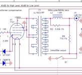
There were a number of revs of that circuit and a number of schematics posted and one IIRC was with LL1660 in both positions.
Once upon a time there was a schematic version posted that listed three transformer brands tried (Lundahl, Sowter, Slagle) and the resistor value changes needed for each one. Looks like your posted image is from a much earlier version. Maybe somebody here has the later more detailed scheme with details? (or on Dave Slagle's forum? . . . . or the designer , member stephe ?)
Once upon a time there was a schematic version posted that listed three transformer brands tried (Lundahl, Sowter, Slagle) and the resistor value changes needed for each one. Looks like your posted image is from a much earlier version. Maybe somebody here has the later more detailed scheme with details? (or on Dave Slagle's forum? . . . . or the designer , member stephe ?)
Here is one of the schematics that give the choice of either 1623 or 1660 but there is nothing about need to change R values. Looking at the schematic it looks like the two resistors in question combine with the small choke (L2 and L4 on that schematic) to make a filter and weren't intended to be any kind of compensation for the preceding interstage. (Though I'd be curious to hear why there'd be no difference if the source resistance goes from three to a thousand. )
Anyway, the above are pretty old posts , maybe you've finished your build. If so, it would be good to hear how it turned out.
Anyway, the above are pretty old posts , maybe you've finished your build. If so, it would be good to hear how it turned out.