• Article Article
Aftermarket cables for Sennheiser HD600/650 series headphones

The headphone cable aftermarket is particularly infected by "audio jewelry": high-price, low-performance items that fail quickly under normal use.

Unfortunately, the in-box cable that comes with a new set of hd600 headphones - while durable - is unpleasant. The matte rubber texture snags on everything and the cable is weirdly stiff.

Yes, you can roll your own if you can get your hands on the 2-prong connectors, but I can't recommend it. I've bought several different cables of varying prices and success rate, but finally found something decent to recommend.

ALPHA DESIGN LABS アルファデザインラブス
IHP-35S/3.0M [SENNHEISER HD650専用ヘッドホンリケーブル]

The cables are a little stiff, but the fit and finish is excellent and everything feels professionally done. More importantly, there are no microphonics, which is the main issue with headphone cables that your rando amazon/ebay products are likely to suffer from.

1.3m and 3m, 6.3mm and balanced twin-XLR versions. These appear to be discontinued (date from 2014, not listed on the ADL web site), so get-em-while-you-can.

Attachments

  • cable.jpg
    cable.jpg
    34.1 KB · Views: 135

I hate blue LEDs, my solution

Yes, I know, yet another quick blue LED bantering. Personally, I never had a issue with the color, only with the point source of light and it's brightness/undiffused look. My remedy was quick, easy and didn't involve math or resistors. Hot Glue! Whereas I don't typically indulge in hacks of any sort, this qualifies as one. The good news is it's totally reversible. In my case, the LED is lit dimly when the unit is off and on brightly when on. Now, when the unit is off, it's off (can't see it) and when on, a soft blue glow.

I removed the LED by pushing from the front with a plastic tool while pulling on it from the interior of the chassis. Then I put a small piece of scotch tape on the faceplate to cover the hole. This served as a barrier for the hot glue and gave a nice flat surface. Fill the void the LED use to reside in with hot glue, encircle the face of the LED with glue and stick the two together. Hold in place for 20 seconds or so and you're done. For all the data dinks that lurk around this forum, I'd say the negative offset from original position of the LED to the new is 3/16" or slightly less.

Best wishes to all this Christmas season.
Stay safe.

Attachments

  • IMG_0116.jpg
    IMG_0116.jpg
    324.6 KB · Views: 373

Help identifying transformer windings

I have an old transformer which I am told was taken from a tape recorder with ECC83/ECL86.

it has 3 wires on one side Brown, Blue, Red (primary), And 4 wires on the secondary side Green, Black, Yellow, red.

Brown - Blue 71.7 Ohms
Brown - Red 80.8 Ohms
Blue - Red 9.2 Ohms

Yellow - Red 0.6 Ohms
Yellow - Green (No read)
Yellow to Black (No read)

Red - Green (No read)
Red - Black (no read)

Green - Black 194 Ohms

Can anyone tell me how to work out what the expected outputs would be and how to figure out how its wound from the results? also, which of the input pairs would have been for 240V?

Thanks.

Punch P400X1 Thermal Protect Light

I have a RF Punch P400X1 and I ran into an issue where I wasn’t getting any audio out of the amp while it was connected. I started throwing parts at it and replaced the rca input jacks, and all of the transistors that sit on the heat sink. Didn’t change anything. I will go back and check to make sure I didn’t bridge any connections, but I don’t think I did. Any suggestions for next steps or diagnostic tips? I do have the schematic for the amplifier (attached below) and I will attach some photos

Attachments

  • 1405-57251-02-B P400X1 Main.pdf
    1405-57251-02-B P400X1 Main.pdf
    195.8 KB · Views: 81
  • D6D760D5-8C9F-41C9-A951-D822ACEDF645.jpeg
    D6D760D5-8C9F-41C9-A951-D822ACEDF645.jpeg
    561.2 KB · Views: 87
  • B33088B2-87F4-4AED-AB57-DCFFFEF9052E.jpeg
    B33088B2-87F4-4AED-AB57-DCFFFEF9052E.jpeg
    791.5 KB · Views: 100

The bifurcation of "high end" audio -- a vindication for DIY

Looking over the April 2023 Stereophile "Recommended Components" I spied the presence of at least one DIYAUDIO correspondent. Doubtless there are others.

What I was struck by were the number of highly rated ss amps which cost a fraction of their similarly ranked peers. It's like watches...some have great appearance and perform well...some appear utilitarian and perform extremely well....Audemars Piaget vs Timex perhaps.
  • Like
Reactions: Pano

For Sale RStAudio XOno 2019

Full set of PCBs, and parts for the RStAudio XOno 2019

Power supply boards (2x)
Phono boards (2x) with 4x 2SK2145 on each board
EQ board (2x) for different EQ standards
Up board to set the gain output configuration and the EQ settings from the front
Large display
ISP board to load program updates
DC blocker board
ALL PARTS, CONNECTORS TO BUILD THIS PHONO AMPLIFIER

Make me an offer

Velleman K4040 build and mods

Velleman used to offer two tube power amplifier kits, the K4040 and K8010. Both are out of production as of now, and even the manuals are no longer available. Some of the web pages that discuss the amplifiers are no longer available, and the information becomes harder to find.

Since I own a K4040, built from a kit back in 2009, and just revised it slightly, I'd like to open this thread to keep the manuals, mods, and other relevant information easily available for reference.

I start with the two original assembly manuals from Velleman. These used to be publicly available on Velleman's web site, so I hope there it's not a problem attaching them to this post.

In the next posts, I will publish the original and modded schematics and mods I have been able to find and use, links to some resources that are still available, as well as some pictures.

Attachments

For Sale Pair of Antek AS-1218 100VA 18v power transformers

Up for sale:
  • 2 x Antek AS-1218 100VA, dual 18V, $45 shipped for both or $25 for a single to lower US.
  • Antek AN-0225 25VA, dual 25V, $20 shipped to lower US
  • Antek AN-0212 25VA, dual 12V, $20 shipped to lower US
  • Signal Transformer LP-12-3426A 12VA, dual 20V, $20 shipped to lower US
  • Signal Transformer LP-12-3427A 12VA, dual 10V, $20 shipped to lower US
Each Antek transformer comes with mounting hardware.


20230313_173749.jpgtraf1.jpgtraf2.jpg

traf3.jpg

QUAD 34 disc input sensitivity?

Long story short, got a Quad 34 and a Quad 405-2 from a friend. Checking for faults (none found except leaky electrolytes), recapped and put everything together again. Everything seems to work just great but I find the disc input too sensitive. The disc module seems to be the MM module, marked; 3mV, 47K/220p. I checked all components against the 3mV schema and everything checks out (except E5270 in the schema being BC413C on the board). I hooked it up to a Technics SL-23 with its National Panasonic 270C-II cartridge. I expected levels to match up but it plays pretty loud even with the volume control at the first position (1). The user manual state expected normal listening levels somewhere between 12-17. The other inputs behave like expected. I feel kind of lost right now, anyone experienced something similar with the Quad 34 disc input?

Attachments

  • IMG_0990.jpg
    IMG_0990.jpg
    148.9 KB · Views: 260
  • IMG_0991.jpg
    IMG_0991.jpg
    114.9 KB · Views: 246

Lundahl Power Transformer for sale

I have one lightly used LL1649 Power Transformer to sell. See here for Specs:

https://www.lundahltransformers.com/wp-content/uploads/datasheets/1648__51.pdf

Lundahl list price is 168 EUR. You can have it MUCH cheaper than this.

Postage is not going to be cheap, but I will do my best. Probably more interesting for European buyers as I am located in Switzerland.

Message me if you are interested!

Ian

F.S. A pair of Verity Audio’s Fidelio Speakers in nice condition.

Good Afternoon Everyone. Am selling a pair of Verity Audio’s Fidelios speakers in the black gloss finish. I would rate them a 8 do to spot on the right speakers top right front corner. (I blow up the picture so you could see it zoomed in on).Also the binding post are missing the inter post you screw in. No other marks that O can see. Comes with the all floor spikes. No boxes or manuals or white gloves it came with. Also this is the top sealed version and not the upgrade certificate the ported top cainent. I did e mail the owner and the only differences between the 2 versions are the port in the top cabinet and a sold peice of Aluminum used between both cabinets and a all wood fight case and not cardboard used to ship the speakers in. Am looking to get $1,500 for a pair of these speakers. I will throw in a pair of Studio 20 speakers in good condition and they work nice. If you come and pick up the speakers at $500.00 value. Plus am saving you a lot money on the Verity speakers because am looking for a quick sale. Just e mail me with questions or info on these speakers. I will have them wiped down and ready. Thanks Jeff
B483F6DD-D739-4DD7-8845-04377362A051.jpeg
8A5A7D9F-8981-4C94-BAB8-6FE3936D18D7.jpeg
70947C73-8D09-4466-B028-C23419D434A9.jpeg

Proposed new website to replace HifiEngine?

Hi! Does anyone know if

fixitguy09

was successful in his efforts to set up a website to replace "HiFiEngine"? Our small church, Grace United Church of Hornepayne, is almost-certainly going to close permanently at the end of June. In going through some of the church's equipment (which will either be sold or given to "good homes") I realized that we had a number of instruction manuals and owner's guides (but no SERVICE manuals) that might be of interest to SOME audiophile do-it-yourselfers. Generally speaking the devices range from low-end-consumer quality to "medium"-level-audiophile quality... and, I am HOPING that, since all of them are of 1970ish-to-1990s vintage (i.e., from BEFORE manufacturers were able to provide downloadable literature), copyright issues won't be a concern... as long as their manuals are used for NON-commercial purposes. In any case, I have done some some scanning and now have six PDF files (for 5 different devices plus one supplemental file) to share. I have already uploaded them to https://www.manualslib.com/, which is a "general-purpose" manuals repository. However, these files might be more useful if made available from a website specifically focused on supporting the AUDIOPHILE DIY community.

Exicon ECX10n20-EXC10P20 Matched Laterals

Hello all,
up for sale are some Exicon lateral mosfets EXC10N20 and 10P20.
All are brand new
This was a special order from Exicon and are matched parts.
Price is 18 euros per pair
Paypal plus fee.

Attachments

  • 1672083369187.jpg
    1672083369187.jpg
    880.1 KB · Views: 255
  • 1672083369198.jpg
    1672083369198.jpg
    941.7 KB · Views: 233
  • 1672083369208.jpg
    1672083369208.jpg
    787.9 KB · Views: 209
  • 1672083369218.jpg
    1672083369218.jpg
    725.4 KB · Views: 160
  • 1672083369227.jpg
    1672083369227.jpg
    487.9 KB · Views: 163

Little problem with Leap 5

Hello

I have a little problem with LEAP 5 EnclosureShop and CrossoverShop.
All perfectly updated to 5.2.0.363 and 5.2.0.351 respectively.
I can't produce a SPL-Z graph using the "Data Transfer" function, which is a simple task which shows nothing hard to understand.
But it is perfectly working well when using LMS for Windows.
But when using LEAP5...
Final SPL-Z shows perfectly fine in "Guide CurveLibrary" after "Data Transfer" was used.
But show nothing, no curve at all in SPL Graph, not even the curve text in the "Map" section, down the page.
Anyone have seen this or better, have a solution for it?
Thanks in advance!

Luke

debugging a TSSA 1.8

Happy new 2023! Well, not that happy for me as I'm having tough times debugging a channel of my primary amplifier. It has served me well for about 8 years.
It's a TSSA v1.8 CFA amp from SITO audio here on DIYA. Unfortunatelly, Sonny, amplifier's designer is not hanging around anymore.
I hope to get some debugging help from more expert members than me.

The trouble started after testing different PSUs and grounding techniques. Long story short I have one amp channel working and the other not, acts weird.
All worked with stable bias with the bulb tester and without the bulb tester. Just after plugging it to my main system it went south.
It could have been due new thermal compound on mosfets and insulators. Even though I have tested all for non-conductivity before firing up.
Can't come up for any other causes for malfunction at the moment.

The driver mosfets seem to be alive. Measuring with DMM show up same values between not functioning and functioning channel.
I have put two amplifier modules side by side and went through most of the R and Q components measuring them in circuit, comparing between the channels.
Couldn't find any discrepancies except Q8:

positive on the gate, negative on the source
1.856V good channel
1.129V bad channel

positive on gate, negative drain
1.8V good channel
1.055 V bad channel

Not sure if that helps anything.

The amp is powered with double mono PSU. At the moment I have only one channel mounted and connected for testing.
Connex SMPS 300RE PSU rail voltages when unconnected are +35V 0 -35V
When connected though it reads weird. Please have a look at this video showing reading between positive and 0
Also please take a look at this video showing jumpy offset readings.
The amplifier module also makes a pulsating "tsk, tsk, tsk..." sound.

Attaching pics of both sides of the malfunctioning amp module.

Any help appreciated 🙏

Edit: Schematic attached with author's permission.

Attachments

  • IMG_4880.jpg
    IMG_4880.jpg
    470.1 KB · Views: 313
  • IMG_4879.jpg
    IMG_4879.jpg
    528.4 KB · Views: 313
  • Screenshot 2023-01-02 at 18.19.27.png
    Screenshot 2023-01-02 at 18.19.27.png
    328.8 KB · Views: 299
  • Screenshot 2023-01-02 at 18.19.37.png
    Screenshot 2023-01-02 at 18.19.37.png
    253.9 KB · Views: 332

Therapeutic massage of the ear-lobes

...with coconut oil, and the strongest intoxicant you might dare to imbibe.

The recipe is obviously going to be different for everyone, but me it was mushrooms, and quite frankly, knowing my Peter Pan capabilities, I'll probably find something even stronger before the rock I've been kicking down the dirt track finally gets wedged between something unkickable.

I wouldn't get too hung up on the intoxicant as it's entirely optional, but I'm just throwing it in there as I'd like to be accurate. A hardly ever drink alcohol any more unless it's home-made wine without sugar or other additives. I have a very simple recipe for white wine (for beginner's luck)
1) pretty much leave the vines alone. I agonised over the red grapes, which they repaid in kind, so the white grapes were kind-of forgotten about until I saw how they were going a nice gold and clear colour. So I put them in a bucket and mashed them with my bare hands. Not counting seeds or anything like that, just making sure the grapes were properly popped to let the juices out.
2) Commit to drinking the mess you just made. Eventually. For me, I didn't let anyone talk me into adding sugar or any other horrible additives. When there's family around, pro tip: never show uncertainty about what you're doing unless you want your wine to taste like it's been designed by a committee.

So, about the hearing thing, what I did was:
1) Sit in the sun all day, preferably topless, even if you can see the ice crystals growing in real-time on the tips of your nipples from the wind chill. Do not skip this step. Something to do with getting a big dose of natural vitamin D to de-calcify the tissues that are supposed to be soft and supple, and re-calcify the bones.
2) Start meditating at a slowish pace, and build up into the evening to get into a relaxed state of mind. For me, alcohol seemed like a bad idea. I got a 0.5% free IPA, but hardly touched it because it was too fizzy after all that sin, I mean sun. Beautiful Freudian slip.
3) Take care of your sun-burnt face by splashing small amounts of cold water onto it, and let it evolve into an intensifying massage of the entire scalp, and add minimal amounts of coconut oil onto your palms. I don't know exactly what the sunlight or its natural vitamin D does, but starting with loosening up all the tight cartilage in my nose, building up to a very strong massage where both my palms were mashing my face with all the force I could muster, like I would imagine in a game of rugby or something like that. I was able to work my way round to my ears — I won't mince words, I was terrified that I might pop my ear drums, or somehow injure them. But far from breaking anything, I was astonished how soft the ear cartilage could be. It was like that spoon bending exercise in the matrix. I figured that if my ears had survived going through a birth canal once, they could probably do it again! Or something like that.

In all seriousness, it seems like classical case of taking matters into your own hands. Really mincing the heck out the cartilage, almost daring it to break at first, but building up slowly, and then watch the capabilities of your own body in amazement. As the nervous tension drops away, I came to imagine that my own neurons had been keeping my ears cramped in a very stale position for years, and my hands closed the feedback loop, allowing me find and soften those tense areas.

Adapting a 2A3 mono power supply for stereo use...

So... I'm diving into another amp project with the goal being to adapt a Loftin White-ish 2A3 mono amplifier schematic for stereo use. It's from Isamu Asano for MJ Magazine. This will be my first build directly from a schematic and I'm excited to dive in.

My question is regarding modifying the power supply to feed two channels. The audio side seems pretty straightforward and I'll be using a similar power transformer with a primary wired for 120V AC. My question is what happens downstream of the PT after the rectifier? Any articles, information or project specific tips would be super helpful and appreciated as I'm here to learn.

Please see the schematic below.

Thanks in advance!

Screen Shot 2023-03-20 at 12.30.36 PM.png

hijack Shark DSP chip Pioneer VSA AX10i

hi is it possible to reprogrammed somehow the dsp chip of my pioneer vsa ax10i to perform digital crossover and eq inside the unit then making use of the multichannel amplification and volume control .
I like my amp and am trying to find the best way to use it for an active multi channel speaker project . I was at first hoping to use a pc and send through optical to the dac now I've found out optical can't transit multiple channels in high quality audio I then though I might be able to make use of the firewire 400 input this model has ... that doesn't seem realistic so thinking about it today is there any way of using the dsp already in the receiver or some kind of USB converter to send the digital signal straight into the dsp chip inside

thanks James

Basic question about bass reflex alignment

I began to get some feedback about my typical BR preferences, saying that I'm tuning the box too low. This will damage the woofer, said my friends. I have never had a problem with any driver blowing out, because I only build speakers for living-room use, no discotheque, and it's possible I've simply been lucky.

So, I decided to show you various alignments and seek your help. What would you do? Please note that I'm looking for an approach which works for my context -- domestic hi-fi, not auditoria or discos. All these are done in Unibox, for the SB Acoustics SB17NBAC aluminium cone 6.5" midbass. My doubt would apply to any bass reflex box for any other driver too, of course.

This is the first alignment -- 25 litres, Fb 35 Hz. If you've not used Unibox, then I'll draw attention to the red line -- that's the line which is the basis of the objections my friends are raising. The red line shows the max SPL for each frequency based on excursion limit. The thick blue line is the actual modelled SPL which the driver will generate (diaphragm + port) if the driver had infinite excursion. Therefore, this graph tells me that if I operate at rated power (60W), then I'll hit excursion limit at about 100Hz. Below 100Hz, the output of the speaker will be excursion limited. At about 40Hz, you can see that the gap between the excursion-defined limit and the modelled SPL is maximum -- it's about 16dB.
sb17nbac-trial-25litres.PNG


The next one is 15 litres, with Fb of 40Hz. Here, the max gap between the modelled SPL and excursion-defined SPL is about 10-11dB, at 50Hz or so.
sb17nbac-trial-15litres.PNG


The third one is 10 litres. In this one, the gap between the two has reduced to about 7dB.
sb17nbac-trial-10litres.PNG


In this one, we have 8 litres, Fb of 38 Hz, and the F3 has now gone up to about 60Hz.
sb17nbac-trial-08litres.PNG


What would you use, and why? I would use either the 25-litre alignment or the 15 litre one. How seriously does one need to keep the modelled SPL close to the excursion limit? And if I am expected to keep it very close, then what's the point of having such a high F3 -- it becomes a midrange driver, not a midbass, almost.

Looking for your insights.

How to simplify tone board to remove bass and treble pots and circuitry?

I have an early 1990's Sherwood receiver model RX-4010R. I currently have the tone board (preamp) removed and am wondering if it is possible to eliminate the circuitry related to bass and treble controls. This is a lower-end receiver, but it does have RCA pre-out and pwr-in jacks. So I could use it as a preamp to drive other amplifiers.

Ideally, I would like to have the simplest circuit possible, eliminating as many unnecessary components a possible.

In the schematic jpg posted below, please disregard the pink and yellow, highlighted electrolytic capacitors and the red "preamp out" marking. Those were done a while back and have nothing to do with the questions I am asking in this post.

But the areas circled green, red, and yellow, do relate to the topic. As can be seen, this design uses two dual opamps. I am not sure which half of the opamp actually drives output, or what determines gain as the resistor values and connections are very different for each half of the opamp. Beyond my understanding, and that is why I came here to ask 🤓

1) is the circuitry circled in green the basis of a simple, opamp based preamp? What more would be required to make this workable?
2) can I eliminate all of the components circled in red?
3) regarding the components circled in yellow, basically whatever is connected to pins 5, 6, and 7 of the opamp, if the tone circuitry is eliminated, does anything need to be connected to those pins? Would there be any harm in using only 1/2 of the opamp?

DSC08199rs1600 marked02.jpg
DSC08203rs1600.JPGDSC08021rs1600.JPG

Exemplar DAC, Shunt Regulated 6H6Pi Output Stage

This was a one-off made by Exemplar 20 years or so ago that he later added his updated tube output stage (2016ish). I pulled it out to sell (I'm moving and can't keep much) and found it not working. I don't think it will take much to get it going again but it should definitely go to someone who can. The dac is shunt regulated pair of 1543s. I added tantalum i/v resistors later. The tube output stage is shunt regulated 6H6pi and sounds fantastic. I'll include the tube dampers. There's a bunch of finemet beads around the power supply and elsewhere, a bit of Stillpoints ERS paper I added later. Really, this dac sounded better than it should have given the dac chips. It has a nice wood front and I thought someone might want to clean it up, reuse the output stage and chassis and find a different dac. I will remove Exemplar logo before shipping. $320 shipped in the USA

Attachments

  • 20230226_200811.JPG
    20230226_200811.JPG
    405.3 KB · Views: 150
  • 20230226_200836.JPG
    20230226_200836.JPG
    454.5 KB · Views: 157
  • 20230226_200532.JPG
    20230226_200532.JPG
    651.1 KB · Views: 156
  • 20230226_200559.JPG
    20230226_200559.JPG
    426.7 KB · Views: 173
  • 20230226_200607.JPG
    20230226_200607.JPG
    482.8 KB · Views: 133
  • 20230226_200629.JPG
    20230226_200629.JPG
    483.8 KB · Views: 139
  • 20230226_200853.JPG
    20230226_200853.JPG
    311.6 KB · Views: 157

Unison Research Simply 4 schematic

Hello to all

I can't contribute much here but I did find on the forum an official schematic for a Unison research Simply 2 so thought it worth showing my schematic for a Simply 4 Pentode (S4P), reverse engineered from my amplifier. I have worked on electronics over the years but not for some years and have little formal training. I've just dug out my Valve Amplifier book by Morgan and will try to understand this better. The schematic may help someone else in the future so I'm putting it here but, I made it really just for my understanding. I believe it's correct but am very happy to be corrected in any parts of my understanding as it's been a while since I've looked at these things. The S2 schematic helped me to get started but it isn't the same.

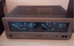
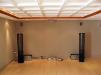
I've owned this S4P since 1996 and it sits in the dining room with some fairly inexpensive speakers and is driven by LP, CD and DAT. It has always sounded fine but this is not the same standard as the living room equipment. It stopped working last week and I investigated. In case someone just finds this on Google, there are HIGH VOLTAGES in here and risk of injury so don't play with your amp unless you know what you're doing from a safety point of view. I realise everyone on this forum will already know this.

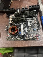
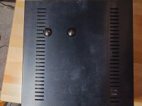
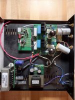
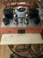
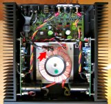
Removing the cage, the top view shows the mains transformer at the rear right (multiple taps), the PSU board and PSU choke at the top left and the output transformers are in each of the two cans - I didn't open these up as I didn't need to. Inputs are at the left front with the selector and variable feedback switch (position 1 or 2). The volume plus source/tape switch are on the front panel with an LED to show the amp is on. The failure was the 10 Ohm power resistor in the PSU board, just due to age.
Unison Research S4P top view.jpg


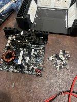
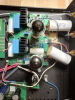
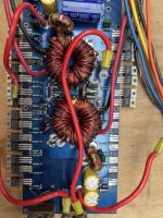
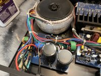
The underside shows as follows:
Back left is the IEC mains input - with a mains switch at the front left.
In front of that is the heaters board - 6.3V AC for the EL34s and 6.6V DC for the ECC82s.
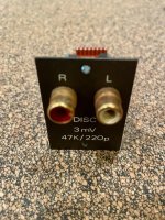
Opposite is the PSU board and the mains transformer output enters at the fuse. The fat red cables (303V DC) feed the main board and an aux socket at the rear for an offboard phono stage. The thinner red cables (330V DC) feed the output transformers. I'm not sure about running these cables with the output cables but this is the way it was built.
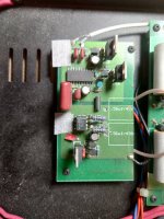
Front right are the inputs and the selector switch board.
In front of that is the volume control board.
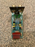
The small board is the variable feedback board.
The big board has virtually everything on it.
Unison Research S4P btm view.jpg


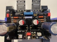
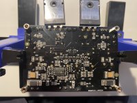
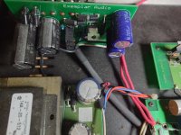
Looking in more detail at the main board (it's quite stained which is poor as I believe this amp has never been opened):
On the left are the heater feeds and the ECC82 feed also runs an LED to show the amp is on.
Top right has the DC feed, earth on the corner and the red and yellow cables on the right are connecting to the feedback board.
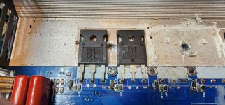
Just below the power connection are a pair of power resistors and an electrolytic cap which are the R8, R9 and C9 in the schematic, directly off the main power feed.
Middle right has a 4k7 power resistor to drop the voltage again to 294V DC as the centre ECC82 uses that. There is a big 400V capacitor at the bottom right which appears to be a ripple smoothing cap (C16).
The volume pot outputs to the board are at the front coming in at the film caps.
The centre ECC82 (V6) is used for both channels - triode 2 is for the right.
The pairs of blue and white cables at the top are the anode and screen connections to the output transformers.
The left part of the board is for the right channel and that's what I have drawn the schematic for but it covers the whole board.
Unison Research S4P board.jpg


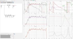
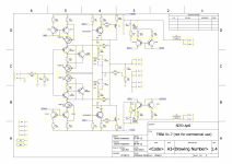
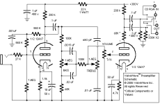
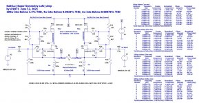
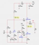
First half of the schematic shows the PSU and pre-amp stage.
After replacing the resistor, I measured the DC voltages and they are shown.
I also ran a small sine wave signal (1KHz and 10mV at the input to V6) in to check stability of the signal with the scope - values in green
The PSU seems clear to me - I didn't look into the mains transformer.
V6 is (as I recall) a standard cathode bias topology (only triode 2 shown here for the right).
V5 triodes are in (I think) a Shunt regulated Push Pull configuration. There is a feedback loop here.
Unison Research S4P schematic 1 of 2.jpg


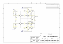
The second half of the schematic shows the HT, signal, feedback loop and ground from the first sheet.
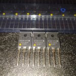
The EL34s are in parallel and I believe this is an ultralinear (Blumlein) configuration. This is the same topology as the Simply 2 but with paralleled valves.
On the right are my resistor equivalents and my notes on the valve pin-outs (as I say, it's been a long time).
Unison Research S4P schematic 2 of 2.jpg


Any comments and corrections would be gratefully received. It's been interesting to go back and try to understand this after so many years but I'm not expecting much feedback. I just thought that the next time someone searches for this schematic, they will have a start.

Best wishes, Chris

Anything sonically resembling the SA-2 monobloc?

Greetings. Just watched Papa going through his rare transistor inventory and it got me wanting to build something class-A now. I need a project!

I still dream of my beloved Threshold SA-2’s. Does anything DIY- to anyone’s experience, sound anywhere close to the SA-2, if you have experience with it? I stupidly sold mine and not a day goes by that I don’t kick myself over it! TIA.

This was one 2-channel system with my dear Thresholds, a Shanling hybrid SACD and Martin Logan Aeon’s in a dual-function home theater I designed- before everything was hidden away in cabinetry.

Attachments

  • 0D6EC17F-3E8F-49F5-AB6F-C33E17D419F2.jpeg
    0D6EC17F-3E8F-49F5-AB6F-C33E17D419F2.jpeg
    788.2 KB · Views: 137
  • 7B9758A7-40FA-4B71-83F9-3064922FD261.jpeg
    7B9758A7-40FA-4B71-83F9-3064922FD261.jpeg
    834.1 KB · Views: 117

Appropriate Crossovers for Two Way Speakers

Hey all I'm trying to put together some cheap speakers for general listening in my garage. So far this is what I've landed on for the components
Screenshot_20230317-185323.png


My question is what is the correct ohm rating crossovers I need? The frequency response for those mid ranges are like 100hz to 4k. I'm gonna put the crossover before the midrange to block out 250hz and below and then wire the tweeter and mid in series for an 8 ohm load. Do I need an 8 or 4 ohm?

Also plan on adding mid bass speakers for 80hz to ~ 300hz. Anyone have any recommendations for cheap woofers under $40

Castle Accustic Pembroke Speakers crossover capacitors DIY update help please.

Hi bought this beautiful speakers Castle Acustics Pembroke 8ohm 88db for 1W and power handling is 75W second hand for very good price and im planning to update crossover capacitors . Im using small stunning Rega IO amplifier, its 30w per channel amp. Amplifier is generally warmer sounding and smooth . Problem is this combo is missing clarity and bass . I love design of speakers and im on budget too , this is my first hi-fi set up ever,I would like to replace old capacitors EXPOTUS 4.7J 250V MPP and second one is EXPOTUS 10.0J 250V MPP for new one to bring more clarity and bass to life . Please see photos of existing crossover and capacitors , Could you please kindly help me to choose best value capacitors for updating cross over?Thnak you
Please see attached Photos
IMG_8991.jpg
IMG_8992.jpg
IMG_8993.jpg
IMG_9016.jpg
IMG_9017.jpg

Marantz 250 output latchup.

This almost 50 year old beast has an issue - the output rail of one channel is prone to latchup. Sometimes it works OK but sometimes speaker rail is at +Vcc. Testing board alone on bench with a current limited supply (50v, 100ma limit) it sometimes works, sometimes doesn't (usually the latter). Making threatening gestures with squirty freeze on the semis does not change its mind. Anyone ever met this (and solved it)?.

Estimating missing T/S parameters for vintage driver

Hi everyone, first time poster and first time speaker builder here. Apols if there are good answers to these questions in a thread already - if so, please link!

I'm planning to build some simple 2-way speakers for my first build, using pre-loved drivers that I have to hand (having previously picked up cheap). The drivers are:
  • Philips AD 1256/W8 (12" bass driver)
  • Electro Voice T35 (tweeter)

I see this very much as a trial run/learning experience. I want to get the best result I can with these drivers, by playing with enclosure size/design (I'm not too limited in terms of size and I'm handy with MDF) and cross-over parameters. That's my plan, anyway! Of course, I'm not 100% certain at this point that i'll get good output across the spectrum with these drivers in a 2-way set up, so I'm prepared to change plan if i have to.

As a starting point, i want to measure the T/S parameters for the Philips 12" drivers, to enter into Vituix CAD software. The drivers are old (early 1970s) and i can't find the parameters online.

I have access to a DATS 2.0 testing system. The DATS gives me most parameters, but I'm missing a few that are the software needs - Sd, Pmax, Xmax, Rms

Given my end goal here, I was hoping i could just guesstimate reasonable values for the missing parameters, perhaps based on similar drivers or a rule of thumb etc. I realise this might sound naive and/or sacrilegious(!) but at least it'd allow me to get started.

So, I'd love some feedback on realistic estimates/ranges for those parameters, for the Philips drivers. OR - any advice on other ways to proceed?

cheers,
Steve

PS
Here are the parameters from the DATS:
1677054578261.png


Here's the Vituix window, showing the blank values that I don't get from DATS:
Screenshot 2023-02-22 212845.png


Here's a photo of the driver
image2.jpeg

Practice headphone amp

I hope this is the right sub-forum to post. I'm in doubt as this project also involves solid-state components and it's an instrument amplifier. Feel free to move it to the most appropriate space.

I would like to build a guitar practice amplifier for a friend of mine. He would rather play with his headphones in order not to bother his flatmates.
Having a spare 12AX7 tube on hand I though I could go with a tube preamp section and a solid state final stage to drive his headphones (they should be low impedance, certainly below 100ohm).
Using the schematic I have attached * I would only need to buy some passives (I already have a suitable HV power supply) and I already have the tone controls sorted out.
So I guess what I am missing is a solid state final amplification stage to drive a pair of headphones. My aim is to use a single rail 12V supply which I already have on hand, but for other voltages I am open to using a buck converter.

I am asking for your advice on two topics:
  • What driver circuitry should I use for the headphone amplifier?
  • Do you have a different/better tube preamp schematic (using the 12AX7)? is there anything you would change in the current design?

* The schematic attached comes from here, but I've uploaded a copy for future-proofing.

Attachments

  • sch.png
    sch.png
    5.4 KB · Views: 118

For Sale NOS Sanken 2SC2922 & 2SA1216

SOLD !

I'm selling 8 pairs of Sanken 2SC2922 & 2SA1216, MT200 transistors, I've had these for about 22 years as replacements for Elektor's Class A amplifiers. They are Hfe grade 'Y' -> = 50 to 100. I have 10 Mica Insulators MT200 they are Including. Two of these 16 pieces, two 2SC2922 were soldered, see attached picture. The price for all 16 is €100 for the entire lot. If you are interested send me a PM. The prices do not include PayPal and shipping costs. Shipping from Finland. PayPal is accepted, the buyer pays the additional 5% PayPal fees. The shipping costs may vary depending on the country.

Attachments

  • Sanken 2SC2922 2SA1216 (1).jpg
    Sanken 2SC2922 2SA1216 (1).jpg
    216.1 KB · Views: 160
  • Sanken 2SC2922 2SA1216 (2).jpg
    Sanken 2SC2922 2SA1216 (2).jpg
    211.1 KB · Views: 133
  • Sanken 2SC2922 2SA1216 (3).jpg
    Sanken 2SC2922 2SA1216 (3).jpg
    221.1 KB · Views: 123
  • Sanken 2SC2922 2SA1216 (4).jpg
    Sanken 2SC2922 2SA1216 (4).jpg
    239.8 KB · Views: 132
  • Sanken 2SC2922 2SA1216 (5).jpg
    Sanken 2SC2922 2SA1216 (5).jpg
    252.3 KB · Views: 133

SuSyLu Where Are You?

Edit Nov 2, 2021: Gerbers for the LuFo amp PCB needed for this project can be found here. A huge thank you for JPS64 for his generous time in making these layouts for the DIY community!

This is a spin-off of the LuFo amplifier discussed here, but it is sufficiently different enough that I did not want to confuse the technical detais already discussed in the other thread. Basically take two LuFo's, and connect them to a common inductively coupled choke with two primary windings, each going to ground, and wound such that the phases of the windings are opposite when referenced to a common ground. Then remove the AC coupling capacitors and connect the load directly between the two amps. Drive the amps with a powerful balanced preamp. You now have a balanced output symmetric amplifier. The name, although suggestive of similarities with Mr Pass’ Super Symmetry topology, is clearly not a SuSy per the Pass patent, since there is no intrinsic feedback between the two halves through a resistor as pointed out by Indra and ZM. However, there is inductive coupling/feedback between the two halves via the common core of the transformer load (note the LTSpice directive “K L1a L1b 1”). And as confirmed by Zen Mod below, the inductive coupling via the shared transformer core qualifies this as a SuSy type amp.

This has only been done in LTSpice, but it seems to make sense and the advantages are: DC coupled output, lower distortion, and higher maximum power (100W) for the same PSU rail voltage, in this case, 28v single rail. The dual primaries inductor will probably require a custom job, or a creative person can remove the secondaries from a microwave oven transformer (MOT) and rewind a second primary in the space where the secondary was once occupied. The performance is quite good with an 8w into 8ohm predicted performance of 0.007%THD.

Here is the simplified schematic - you wil notice each half is identical to the schematic for the LuFo amp with exception of no output coupling cap. It would be a good idea to use the nicely matched power JFET Lu1014D's that Woofertester provided using the generous donation of LU1014D's that Mr Pass provided. One needs to adjust the bias currents on each side until the voltages at the output nodes match in order to reduce the DC current that would flow through the speakers since no coupling cap is present. One could install the coupling cap on one side and that would eliminate the DC offset concern. However, that would negate one of the primary advantages. The cascode MOSFETs is shown here as a single unit when in reality, 3x are used to spread the heat load across the heatsink. Schematic edited to show inductive coupling via the transformer loading:
959695d1623680801-susylu-susylu-schematic-v01b-jpg


Here is the simulated time-dependent signal output on the positive leg, negative leg, and the difference across the speaker load for the 8w case:
959590d1623644674-susylu-susylu-scope-8w-asymmetric-inductor-jpg


Here is the FFT for the 8w case with the inductors wound symmetrically at 68mH per side. We can see that they symmetric arrangement reduced second order distortion and so the third order dominates. This has a very solid state feel to the sound:
959592d1623644674-susylu-susylu-fft-8w-bal-inductor-jpg


If we purposely made one of the windings different, say 60mH instead of 68. This will introduce slight asymmetries that will help reduce the third harmonic and other odd distortion figures.
959591d1623644674-susylu-susylu-fft-8w-asymmetric-inductor-jpg


Edit Sept 22, 2021: SuSyLu has been tested and verified to make 100w (31.7Vrms or 89.7vpp) into a 10ohm dummy load with only 27.6Vdc single rail PSU from a 400VA 24v toroidal trafo.

985350d1632334399-susylu-susylu-max-power-dmm-vrms-jpg


985033d1632222333-susylu-8a9b4811-c7cc-4073-8f76-a4799f189a61-jpg


Sound clips here: SuSyLu Where Are You?

Here is FFT for 8.0Vrms into 10ohms, he THD is 0.015%:
985447d1632371457-susylu-susylu-fft-8-0vms-10ohms-jpg

Attachments

  • SuSyLu-Schematic-v01.jpg
    SuSyLu-Schematic-v01.jpg
    275 KB · Views: 2,427
  • SuSyLu-FFT-8w-asymmetric-inductor.jpg
    SuSyLu-FFT-8w-asymmetric-inductor.jpg
    141 KB · Views: 4,258
  • SuSyLu-Scope-8w-asymmetric-inductor.jpg
    SuSyLu-Scope-8w-asymmetric-inductor.jpg
    167.4 KB · Views: 4,317
  • SuSyLu-FFT-8w-bal-inductor.jpg
    SuSyLu-FFT-8w-bal-inductor.jpg
    133.9 KB · Views: 4,263

Not working digital out board in a TEAC VRDS-9 player: any experience of this?

Hello,
the board is not working. It receives power and digital signal, but nothing comes out of either output - the coaxial and the optical.
Does anyone have any experience of a similar issue so that I can try to pinpoint where the problem is? I am not sufficiently equipped technically to check the whole board myself, so waiting for some help from a technician I am asking here.
Thanks
H

Attachments

  • IMG_0142.jpeg
    IMG_0142.jpeg
    286.1 KB · Views: 120

Noise on the mains supply [in or out?]

So on the topic of noise on the mains, some will come from the incoming mains (outside) and some will be generated from what is in your house (inside)

I have no measurement equipment so I can't confirm in my case, but I would be interested to know in general if proximity to the source is a significant factor and so the majority of noise comes from (inside) or is it mostly from (outside) the property travelling in from everybody else on the line?

Any ideas?

Thanks,

For Sale Constant Current Diodes J503 (0.45ma) - J505(0.80ma) - J511(4.70ma)

Selling various constant current diodes from Vishay Siliconix, 70 x J503 - 100 x J505 - 70 x J511, they are bought from a German distributor. I would like €3.00/piece. They are still in sealed bags. The minimum order quantity is 20 pieces. They seem to be only available from Mouser now and cost about 7Euro each. The prices do not include PayPal and shipping costs. Shipping from Finland. PayPal is accepted, the buyer pays the additional 5% PayPal fees. The shipping costs may vary depending on the country.

Attachments

  • IMG_20230317_055529.jpg
    IMG_20230317_055529.jpg
    204.1 KB · Views: 89
  • IMG_20230317_055605.jpg
    IMG_20230317_055605.jpg
    256.8 KB · Views: 77
  • IMG_20230317_055607.jpg
    IMG_20230317_055607.jpg
    250.6 KB · Views: 81

How large should be my port

Hi my friends! I am complete new into this hobby of building speaker boxes and after making a lot of research I still couldnt discover how to solve this question.

I have 2 speakers (125w RMS - Taramps 7driver HD 250S) which have a really really really nice sound (from low-high). I built a box with the following inner dimensions: 30 cm wide, 20 cm tall and 15 cm depth = 9 liters. The wood is 1cm thick however the front panel is not thick so I could easily cut the holes (it's 3mm and I will surely improve the thickness of the front wood in the coming days). Picture below:

a.jpg


I know I should use a much larger box with these speakers, however I dont have any space left for the place where this box will be placed in my house.

My question is this: I already made a hole in the box with a diameter or 6cm to put the port. My question is: how long must be the tube that I will insert into this box in order to get a good low bass (30 hz? maybe 40?). You can see in the picture below I 3D printed a tube with 6cm diameter and 10cm long, but I still dont like the bass (it does not improve much when compared to have the box sealed).

b.jpg

KT150s are really nice!

I just complete a KT150 SE amp and am thrilled with the results! It also takes the KT120 but the 150 sounds even better with more clarity and definition in the low end. Mids are smooth as are the highs. Imaging is fantastic in all directions. I’m using LED biasing on the input tube which can be anything from a 6DJ8 family to a Russian 6N6. I really like the 6N6 for its low end. The PS uses all film caps and is dual mono with an Antek toroid power transforder. It has separate windings for each channels HV and filament. Anyone else using the KT150 in a SE amp?

Attachments

  • 63B36E8B-9B9E-4A81-8687-5D0CDBC2B677.jpeg
    63B36E8B-9B9E-4A81-8687-5D0CDBC2B677.jpeg
    448.5 KB · Views: 272

Single End Class A, No Global Feedback with J113 and IRFP240. 4 Watt.

  • Single End
  • Class A
  • No global Feedback
  • 2 Stages with J113 and IRFP240
  • Max 4-5 Watt

Here is the simplified idea.

And the actually fully working circuit.
It can deliver more than 5 Watt into 8 Ohm.

Attachments

  • J113 IRFP240 Single End_Simplified.jpg
    J113 IRFP240 Single End_Simplified.jpg
    13 KB · Views: 732
  • J113 IRFP240 Single End 067.jpg
    J113 IRFP240 Single End 067.jpg
    44.4 KB · Views: 539
  • Like
Reactions: Haze Head

Sources for a long round cross section belt

Looking for a round belt ideally 2-2.5mm thick to drive a 310mm platter has proven to be more difficult than expected. Or maybe i am approaching this the wrong way.

The flat belts that fit my platter are about 1020mm long so i assume a suitable round belt should be of similar length. Haven't had much luck finding one so far.

1. Acoustic Signature seems to offer two belt sizes for their subplatter and circumference driven turntables, correspondingly 490mm and 900mm. 900mm is less than the circumference of their platters, does that mean their belts are very stretchy?

2. Project offers a lot of belt sizes and shapes for their turntables. They do not disclose the actual sizes but it seems the longest is 97mm (RPM10 perhaps). The thickness still remains unknown but from the pics it looks very substantial. Project also sell 3mm pulleys, some of which perhaps fit their own belts.

Project belt resellers in general seem very reluctant to supply Project belts to other turntables. Belt sizes appear to be a carefully guarded secret.

3. VPi?

4. Clearaudio?

5. Others?

For Sale TV Damper Diodes

6DA4 6DM4 6AX4 6AU4 etc. - all very nice in boxes, tested, etc. GREAT for slow start B+ rectification.

B825E919-0978-4A30-9E0D-622082AA2F59.jpeg

Attachments

  • 8F22DB06-0E99-4104-950F-199D7A4F7AFD.jpeg
    8F22DB06-0E99-4104-950F-199D7A4F7AFD.jpeg
    338.1 KB · Views: 73
  • 8523F9FA-A81A-461A-819D-6DB0489A8449.jpeg
    8523F9FA-A81A-461A-819D-6DB0489A8449.jpeg
    500.3 KB · Views: 74
  • C6847FA6-2346-4811-8866-7DE5B4FAF408.jpeg
    C6847FA6-2346-4811-8866-7DE5B4FAF408.jpeg
    478.9 KB · Views: 74
  • 8EFD6EC0-4CDD-4940-8CFB-D9B6522057A1.jpeg
    8EFD6EC0-4CDD-4940-8CFB-D9B6522057A1.jpeg
    344.7 KB · Views: 65
  • 26D80777-284A-4EBA-BC1A-5891BBB26A40.jpeg
    26D80777-284A-4EBA-BC1A-5891BBB26A40.jpeg
    281 KB · Views: 66
  • 612EF651-C195-49BA-9D24-911B731B8D8A.jpeg
    612EF651-C195-49BA-9D24-911B731B8D8A.jpeg
    348.2 KB · Views: 68
  • E6F6195A-6DD9-4A5E-87FE-71B342C9F0FE.jpeg
    E6F6195A-6DD9-4A5E-87FE-71B342C9F0FE.jpeg
    312 KB · Views: 66
  • 9DD5AD7E-F39B-49B7-BB77-9DEC449DE756.jpeg
    9DD5AD7E-F39B-49B7-BB77-9DEC449DE756.jpeg
    241.4 KB · Views: 66
  • F94C7307-A70B-4FAE-BF39-93C3E13A8BA2.jpeg
    F94C7307-A70B-4FAE-BF39-93C3E13A8BA2.jpeg
    428.8 KB · Views: 71
  • 27A68F88-520D-47DF-B5E6-5FCD8CCF5CB4.jpeg
    27A68F88-520D-47DF-B5E6-5FCD8CCF5CB4.jpeg
    284.7 KB · Views: 72

0-900v transformer noise

Transformer:
Primary 0-230v

Secondary
0-900v
0-200v No noise on load
0-10v No noise on load
0-6.3v No noise on load

AC load without rectifier 6000 ohm resistor = 150mA noise on transformer 20db ( aceptable noise )

DC load with rectifier R-C1-L-C2 ( 50R - 180uf - 15H ( 90ohm) - 470uf ) 6000 ohm on C2 noise on transformer 40db ( too loud )

notes:
Three different transformer ( no potted ) EI124 5kg from two different factories with the same result
I have replace all diodes, cap,resistor and choke without changes
loaded DC with resistor or tubes the same noise ( 2 211 tubes )
Core is correctly lock ( shapes no noise ) noise from bobbin
AC 0-900v secondary line when are rectified has 0.150V DC ( maybe this is the problem )
Noise frequency go from 400hz to 1100hz
AC 230v normally has 0.040V DC

0-900V.jpg


ideas or answer are welcome.

Aiwa AA-8300 restoration ideas

Just bought this lovely amp and after pots and input/ output contacts cleaning, from quick listening it’s worthy to bring it back to its potential.

Maybe not at once, and my abilities are limited, so I would like to ask about what to do first.

I know one enthusiast living nearby, and he focuses more on valve amps and CD players, but he is a pedant, he could help.

The issue is channels imbalance, and perhaps slight tonal differences between them when balanced out.

Left channel is about 40% or more quieter. And also, when listening at low volume, it can just disappear. When louder, it seems stable.

I did not check anything, but DC presence on speakers terminals, there is no DC there.

In the amp there should be just 2 ICs, so mostly it’s solid state.

What would be the procedure to do first to make it balanced, then second, to make it tonally equal?

Thank you.

Attachments

  • image.jpg
    image.jpg
    234.9 KB · Views: 347
  • Like
Reactions: madis64

RSS390-22 Sealed Enclosure Stiffness / Decision issues about bars to stiffen up

Hello,

This is my first Subwoofer Build. I got the Material today and my Question is about the additional Bars to stiffen it. For the 394 mm inside I could set up to 3 per side.
The plates are 38mm/1 1/2 ".

1676474959408.png


ca. 70 L Internal Volume so around 2,8 cu ft

My Idea is to place 1 or 2 Pcs beacuse I want it to sound good and don´t wobble 😀

1676476043566.png


Is Dampening necessary and what is the most effective wall to dampen? the rear wall or the sides?
Should I leave it blank and decide about that after measuring ?

Thank you for your tipps.

Flo

Adding Powered Sub to Vintage Console - - High Pass or Bandpass Crossover?

I have in my possession a mid-fifties consolette, I have brought it back to life, AM receiver and all and she sounds stunning, but of course, two nearly 70 year old 8 inch oxford drivers can only do so much down low. I've modeled nearly every conceivable vented, closed, and horn type I can come up with, and can still only achieve a modeled flat response down to about 100hz, give or take. I would like to enjoy my listening sessions without having to lower the bass pot to save these poor dear old drivers on the few bass heavy tracks in my collection. Inasmuch, I've decided a powered subwoofer is in order, and have decided to incorporate it directly into the console, to keep the existing footprint and the wife approval factor.

I was wondering if it would be better, sonically, to apply a high pass filter to the woofers to protect them, or a band-pass, and full crossover redesign, giving the tweeter more range to play? Mind you, cost on this project is absolutely ZERO object, as this one is to be kept and enjoyed for some time.

With proper power supply would two pair of 2SA1943 and 2SC5200 be able to output 1000 watts?

I was curious if two pair of 2SA1943 and 2SC5200 could possibly output 1000 watts at 4 ohms, well 950. I have a Dayton SA1000 rack mounted amp that I got second hand. I know the 1000 watt plate amp couldn’t make power, but I read that the rack amp was okay.

I’ve been reading that some of them have been dying as the capacitors in them are starting to go. I opened mine up to check ESR and such and noticed that this amp only had 4 outputs. I’d figure for 1000 watts RMS it would have 8 at least. I’ve never seen a standard power amplifier rated at 500w @ 8R and 950w @ 4R with only 4 outputs in each channel. It has well over 100 positive reviews, I was just surprised.

855CE9B5-6B6D-46C9-99E6-A2BE66C9850B.jpeg

270EAD52-61A5-46B7-BB20-6E0A67D3F357.jpeg


Dan

Attachments

  • 2FD03828-F378-4619-A31D-8416D7286E2C.jpeg
    2FD03828-F378-4619-A31D-8416D7286E2C.jpeg
    575 KB · Views: 330

For Sale Electronic components leftovers (relays, bridge rectifiers, EMI filters)

Maybe you need something from here.

Schaffner FN9290-10-100 Filtered Power Entry Module
2 units available. One without outer frame. Never used.

IXYS VBO 22-16 NO8 Bridge Rectifier Module, 17A, 1600V, 4-Pin
16 units. Sealed, never used.

1 Relay modules.
8 units. 5 New, 3 tested but perfect working condition.

Feel free to ask for what you need.
Price? I'd rather prefer to send everything together. An exchange for some wine or any typical food from your country would be more than enough or even better a small amount of money that I will donate to the forum. Up to you.


Sonido 175A Project

I decided to get myself busy with another project and figured I would post some of the progress and eventual results

There has been much I’ve learned from this forum and there is so much I still don’t know and since I haven’t seen many posts about these drivers then maybe this can be my contribution to others.

My goal was to build some more sensitive speakers than my MA-10p’s because I’d like to build a low power tube amp, but the challenge is my room isn’t very large and can’t have huge speakers.

Scott posted some plans on his Tamaraw design for the Sonido 175A and I decided to give them a try.

I just got the speakers, here are some pictures of these.

Wish me luck.

Attachments

  • B6876D7D-507A-4AEE-89C2-4048145C06DD.png
    B6876D7D-507A-4AEE-89C2-4048145C06DD.png
    50.4 KB · Views: 1,012
  • 8472D2A7-57C5-478C-A8BC-A52BB4B15008.jpeg
    8472D2A7-57C5-478C-A8BC-A52BB4B15008.jpeg
    268.1 KB · Views: 974
  • 8154FDC5-D07F-4DE8-8AC4-6AA33BAF3707.jpeg
    8154FDC5-D07F-4DE8-8AC4-6AA33BAF3707.jpeg
    342.9 KB · Views: 891
  • 0CC62875-20FA-4637-B58D-1AD9ECFB0D1E.jpeg
    0CC62875-20FA-4637-B58D-1AD9ECFB0D1E.jpeg
    270.2 KB · Views: 968

WTB Oscilloscope

Looking for an oscilloscope for audio, smps/PWM and rc car motor types of signals. Happy with 2 channels and I am not very particular about features, only that it works and it's accurate. Size or digital/analog is not a concern either, so aiming for a cheap solution.
Located in UK, so I would prefer UK and EU continent sellers to avoid high shipping costs.

Thanks.

DC offset on op amp output

Hello all,

It has been a while that Im searching about the DC voltage offset on an op amp out put and its effects on AC voltage which we care about. I have noticed in some designs that DC offset varies from 35 to few mili Volts on the op amp output. So what would be the effect on AC voltage (if it has any at all)? What are the limits?

I appreciate your consideration,
Cheers,
Alan.

Why dont commercial manufacturers use soft starts?

Hi guys,

I salvage all the cheap faulty home theater amps I can find as they are a great source of power transformers and heatsinks etc.

I have not once seen a soft start system (at least that I am smart enough to recognize).

Some of these amps have 600 or 700w power transformers.

Conventional wisdom of the internet states that anything over roughly 300VA should have a soft start. This is if course stated to toroidal types however my understanding is that regular EI types are not much better.

Am I missing something?

Alpair 12p on wall

Helping a friend put a system together and we're gonna build him some boxes, I suggested the Alpair 12p as I've tried the 10p and was very impressed. I thought the bit of extra directivity from the larger cone would help given we're just going with these with maybe a sub underneath to save some money.

The boxes are going to be right on the wall sitting on a couple of brackets with some sorbothane hemispheres underneath just to decouple them from teh wall abit (condo living) So they'll be maybe just a teeny bit off the wall, but basically on wall on either side of the TV. Sitting distance is 10 feet away, speakers about 8 feet apart.

He has a loft with 16ft ceilings and far away side walls, so its just the width of the room that is small. Very reverberant room, no treatments, concrete floor. Anyhow was thinking of using the following design: http://frugal-phile.com/boxlib/P10free/CGR-Mar-Ken12p-310817.pdf Not opposed to building something even slightly larger as long as its shallow.


Any other suggestions or does this look good? Going to make out of MDF and paint white.

For Sale 20Mhz Oscilloscope - not used but stored in India

I have an Oscilloscope bought years ago 2Ch- 20Mhz - stored in India ( Bangalore) and available for sale. I will be in Bangalore - India ) during 1St Apr till 11th. I will post pictures when I reach Bangalore. Please contact me ( message here) in case you are interested. I had two Probes as well but search among my storage in my Apartment and should be possible to locate when I reach Bangalore

Rockford bd1500.1 going to protect mode

hi guys, recently buy a rockford bd1500.1 amp, right now it is connected into 4 ohms, supposedly it can go down to 2 ohms, and while playing in 4 ohms, when volume is 3/4 of the total and when bass hit, amp goes to protect mode. I switch the radio off and inmediatly on and amp starts playing again. Amp is not hot, and it sounds cristal clear. No evidence of malfuncition inside amp. Any thoughts??

IMG_20230318_141947.jpg

Reel Tape Head Stage vs Phono Stage

I've recently bought a Technics reel to reel deck and have been thinking about getting an outboard preamp for it. Most of them are quite pricey, though, and there don't seem to be any kits around. (Bottlehead used to make one.) If I'm wrong about that, and someone can point me at one, I'd appreciate it.

Anyway, my question is about the difference between a preamp for a reel to reel and a phono preamp. The deHavilland tape head has 52dB gain, which, I see, is about the same as a phono stage. Now, I'm guessing that you can't just use a phono state as a tape head. Can someone tell me why not? Impedence matching or something of the sort? Is there any way to compensate for that?
Projects by fanatics, for fanatics
Get answers and advice for everyone wanting to learn the art of audio.
Join the Community
507,636
Members
7,881,726
Messages

Filter

Forum Statistics

Threads
405,929
Messages
7,881,726
Members
507,636
Latest member
wolstar