Need help with sheet metal work...

Am about to begin building a long-time-planned amp for Bass, and pedal steel. A circuit using 8 1625 finals ( 12V 807s) driven by 12SN7s (12V versions of the 6SN7) into AB2 operation. Not a problem for me to do the circuit-fiddling at all ( so long as I stay out of joining the 650V circuit - and becoming a part of it) The sheet metal stuff has me stymied though. Need to build a decent solid chassis to house 8 807 tubes, a pair of XSN7 drivers, and a XSN7 PI...... with a ******* hand drill, tin snips and Dremel......
There must be an easier way........

CD adjustment set screws - which Loctite to use?

I recently did some work on my CD player. Clean, lube etc. The screws that hold in the laser rails have to be turned a certain amount then locked into place with adhesive. These rails are controlling the hight of the laser so if they aren't exact, it won't read some discs. The screws had clear blue glue on them from factory, but the only blue I know of Loctite Blue threadlocker, which is to be applied BEFORE putting in the screw. Did they just put it on after anyways and it works? or does anyone know what I should be using for this so that it will lock them in place but be easily removable in the future? The screws are metal, the hole/threads they screw into are plastic. TIA!

more treatment talk

How do you treat the immediate area directly behind your stand mounts? I need better panels for power hungry large 4 ohm stand mounts.

I'm thinking 4" deep
w/ loosely rockwool filled
2'x4' two tone wood veneer with contrasts from very light to very dark, maybe even a black pain w/ white maple.

Is 4 inches adequate at that location?, or if pushed down to say 3" thick x 2 feet by 2 feet.

Linn "LINTO" MC Preamp Schematic without SMPS - Schematic for SMPS wanted

I need the schematic diagram from the switch mode power supply. Who can help?

Here the PDF schematic of the preamp itself (please note: first generation Linto, not currently version !!! ) I have created this schematic for the introduce of an interface (to connect an external parallel regulated power supply) some years ago.

Attachments

Luxman C03 and M120a power

Hi y'all.

Recently I was able to buy a Luxman C03 preamp with a Luxman M120a power amp for a bargain (€150).
The sound with my Visoniks was better compared to the sound of my Naim nait XS. Don't get me wrong the Naim is great, but the bass was too much with my speakers.

So the Luxman combo sounded good but needs some love.

In the C03 there were clearly some issues with two power supply capacitors. See pictures.
I replaced them by thexe nichicon caps: LLS2A332MELA
Specs: https://be.farnell.com/nichicon/lls2a332mela/cap-3300-f-100v-alu-elec-snap/dp/8813329

The M120a was really heating up and was smelly. I cleaned it thoroughly and set it's bias correct. It was out of control: up to 200mA instead of a stable 70mA.
Although there was something unclear in the schematics about the testing points for the fuse 801, in the end I did find the correct testing points, zo the bias should be okay right now.

Now: after hooking it all up again, letting it play for a few hours: I do find the bass again somewhat overwhelming.
  • Could the new ps capacitors of the C03 pre have something to do with it?
  • Do they need some break in?
  • Are they the right ones?
  • Something else I'm missing?

Kind regards!

Gr

Will

Attachments

Fisher X-202-C Restoration: Power Supply Voltages too High

Hello,

I am reading from different sources that having higher voltages than what is mentioned in the service manuals is kind of a common thing nowadays as the wall outlet voltage has slightly increased and some even say that having slightly higher voltages is normal with the Fisher gear. However my situation is slightly different.

As for starters, I do not have the right service manual. This manual I have attached belongs to the earlier set of serial numbers. So, I am not 100% sure if these voltages are correct for this X-202-C. However, for 7591 the B+ is around 440V which is as mentioned in the service manual. What I am measuring at the tube pins is 490V. This is of course by controlling the line voltage with a variac set to deliver 120V at the amplifier input. As this is the voltage right after the Fishers’ infamous voltage doubler and the diodes check out ok, I have experimented with inserting a 22ohm 25W resistor between the capacitor and the diode. By this way I am able to bring down the 490V to 440V. And I am not stopping there, I am also increasing the next resistor in line from 1.5kohm (Which measured within tolerance) to 2.7kohm and having the 390V right. After that point all, the voltages fall into their places.

My question is, am I doing something that may cause other issues, or can this amplifier live to see another day with these modifications? I am worried because with these high voltages, I see slight red glow on the sides of the 7591 tubes, and I am worried it may shorten the tube life.

Thanks,
Dirk

Attachments

TubeLab SSE - Potentiometer Recommend

Still working on the parts list to get a rough idea of the total cost before diving in. The volume pot/attenuator is potentially one of the more costly individual items.

They range in price from $10 for cheap generic Chinese to $300+ for stepped attenuators (DACT, Goldpoint, et al.) TKD conductive plastic pots seem to come in about midway in that range. Are they worth the price? Any other recommendations?

Or, my source at the moment is exclusively Tidal so I could dispense with a volume control on the amp altogether and use the one built into Tidal. If I ever want to use vinyl or tape I would probably use a preamp anyway. Thoughts?

Hi from Alabama

Been perusing for years and decided to join. I went to electronics repair school in the 70s and worked in a TV shop for while, then got out to get into lab medicine. use what I learned to repair/refurbish/build my own gear. I have been semi-retired for 4 years now, so I have time to play. I started making my own enclosures a few years ago and I build from schematics, not kits.
Here is a video of my latest build:
Login to view embedded media
  • Like
Reactions: Pano

Onkyo CR-305TX PSU FAult

Hi all,
I'm a novice at component level fault finding so be gentle with me!
I have a ONKYO CR-305TX that I've checked the fuses, but it doesnt power up.

I have located the service manual -
Onkyo CR-305TX Service Manual free download,schematics,datasheets,eeprom bins,pcb,repair info for test equipment and electronics

Looking inside at the PSU there is a lot of paste around the bases of some components - is this normal? (see attached photo)

Attachments

  • DSCF2007_sml.jpg
    DSCF2007_sml.jpg
    170.9 KB · Views: 640

Use JBL 4732A components to build line array cabs?

New member here. I have six 135 lb JBL 4732A cabs. We’re all getting a bit tired of lifting these things, and technology has moved on. That said, the components therein should still be useful to repurpose into single 12” line array cabs. Hoping to build 12 of these for a max of 6/side to use with four 4719A subs. Can anyone point me to a good proven line array cab design I can build out of 13 ply baltic birch that will work with the 2206 12” LF driver and the 1.4” 2447 HF driver? I was interested in Mike Sprague’s LA112 design, but he said it only works with the Eminence Deltalite 2512.

Thorens TD160 tonearm ticks when touched

Hello esteemed forum members,

I have this curious issue with one of the two Thorens TD160 turntables I own. Both have a TP16 tonearm.

The problematic one has this curious behavious: when I touch the tonearm (when in resting potition), I hear a static 'tick' through both speakers. It is just a a tick, I have to wait some seconds before I can make it 'tick' again, by touching it again. The noise is also there when I touch other grounded parts of the turntable, but the sound is loudest when I touch the headshell. The other Thorens is immune to this. I switched headshells but the problem stayed with the turntable.

When I fully remove the headshell, touching the turntable doesn't make it tick (but the machines hums continuosly when no headshell attached, assume that is normal behaviour). Also tried switching the phone preamps, but that didn't impact the issue.

As an experiment, I tried grounding the tonearm with an extra wire. Didn't change things.

Only cause I can think of now is that it is somehow related to the tonearm wiring, but I am hesitant to mess with that.

What could be the cause? What would be the best approach to test or even better fix it?

Thanks a lot,
René
  • Like
Reactions: bedrock602

5 ea Burr Brown OPA637AU

As it says I have 5 of these. They are authentic as I bought them a couple years ago at digikey. These were just soldered on to browndogs to try in my Marchand xover. They don't work properly because of the voltage or something I presume. So I unsoldered them and put them back in the container. I would trade for Opa627au or Opa 627 8 pin dips. I would take 80$ for all 5 and that is a steal. Or I would trade even up for the 627's . Shipping is free at this price. PayPal use friends and family or pay the fees.

Mayware Formula 4 Uni-Pivot arm

Hi all,

I have an old (20yrs plus) Mayware Formula 4 uni-pivot fluid damped arm I want to resurrect that is said to be a pretty nifty little number. My sample is in good condition. Either way it's a cute and attactive unit, just begging to be played with! I have the damping fluid already sourced. These babies were built in the UK and Australia - mine is the latter. I bounced this question off Allen Wright previously - he mentioned JH as the manufacturer, presumably confirming the Ausi connection.

So I need ideas for suitable cartridges please folks. Denon 304 and the 103 have been suggested. 103 difficult to obtain apparently now. I have a number of proven tweaks also for this arm. Am intending to fit to some as yet undefined self built deck - perhaps an Origin Live kit.

I have no MC i/p - so we are talking MM or hi o/p MC - but can beggers be choosers?

The spec for the arm is as follows: Can anyone translate that effective mass figure to matching cartridge compliance figure? Help me out here - hi compliance means what sort of figure? and lo comliance ...

SPECIFICATIONS (cut from UK version set-up manaual)
--------------
Effective length (stylus pivot): 224 mm
Rear overhang required: 65 mm
Height adjustment: 45 mm
Effective mass (as seen by stylus): 4.50 gram nominal+variable
Audio output lead length: 4'6" (137 cm)
Audio output lead capacitance: 112 pF (with phono plugs)
Tracking force: 0 - 3.5 grams
Pivot: inverted hardened steel pin pivoting on jewelled bearing damped by silicone fluid
Pivot friction: Less than 5 Mgm. in any plane measured at the headshell
Mayware Ltd. 15 Heather Walk, Edgware, Middlesex HA8 9TS England

Cheers

Pete

Three level flying cap Gan.

Hi all.


I had idea when corona is in afterworld to go try multilevel, the problem however is the driving of gates who are floating.

I have read some stuff, but simulating it is very difficult, I did see that I even have to use high side driver ic,s and not the LMG1505 whi I try now.

Problem is I use symetrical supply, -60 x +60 volts. Normally I have to put then VSS on the -60 and level shift the inputs. But in flying cap three level I have als supply / 2 levels, and I think I need here isolated drivers.

Do have someone some experience? and why the vdd 5 volts does not work when tied to the -60 volts rail.

I have then use a btl? who by the way give then 5 level when I do shift triangle 90 degree. Maybe the lmg1505 does not work with symetrical supplys.

https://core.ac.uk/download/pdf/158315636.pdf

Here some examples what I mean. This idea for openloop Gan, just curiousity of me, I see nice things happen, amps who are better then class A for example, need to hobby test afcourse in future.

regards

Attachments

  • ScreenHunter 639.jpg
    ScreenHunter 639.jpg
    15.3 KB · Views: 551
  • ScreenHunter 637.jpg
    ScreenHunter 637.jpg
    88.2 KB · Views: 555
  • ScreenHunter 630.jpg
    ScreenHunter 630.jpg
    31.7 KB · Views: 551
  • ScreenHunter 628.jpg
    ScreenHunter 628.jpg
    45.8 KB · Views: 534

Mark Audio drivers as ceiling speakers

Hi. I’m planning a multi room audio system with standard speakers downstairs (all mark audio at the moment). And want to add some ceiling speakers upstairs. Mainly for radio/background music so not critical listening or active Dolby, just really to keep audio in sync across multiple rooms.

Downstairs I have a Roon Core Server which in some form will handle different zones, and would probably drive from a simple dac and Hypex amps or a Bluesound Node/Edge as this has streamer and amps integrated.

So…what would you pick from the current line up of Mark Audio drivers. My main requirements would be;

1. Smallest easiest back box for installation, the house is on the small side of an English home. Sealed cabs to avoid extra space for ports.
2. Lowest cost for highest quality. Ie: would 4-6 CHN-50’s be ‘better’ than a single Alpair 11.
3. Better than an off the shelf system from many of the offerings from install companies (b&w, kef etc)
4. Lower in overall cost than installing one Zuma Lumisonic which although expensive do seem to tick a lot of boxes.

Hope to hear your thoughts.

SFE.TV - Souvenirs For Earth

I think you have to live in France to get this channel. We have Bouygues for TV,i/net,tel. There are loads of channels that we never use. The other evening I decided to go surfing and came across 133 - Souvenirs for Earth - completely unexpected - basically it's ambient with visuals and you never know what's coming next.
First up was completely erotic but no writhing bare bodies just an amazingly beautiful dark haired, dark eyed drop dead gorgeous young woman eating a chocolate coated ice cream on a stick slowly to ambient music - it went on and on until she finished it. Her face was a continuous set ofsalacious sexy steamy changes - man you had to see it. Each time a short film followed one after another, impossible to describe and always with an ambient music theme and always completely off the wall.

If any French members watch this channel it would be nice to hear their opinion.

ES9038Q2M Board and HQPlayer

Hi,

I use the Ian Canada Mono DAC with the Reclocker Q7 on a Raspberry PI 3b. The software platform is from RopieeeXL in order to play HQPlayer and/or Roon.

The situation is that:

1e The max conversion rate is limited to 192K.
2e Only PCM format is supported and DSD is not.

What could cause this limitations>

RopieeeXL is configured with the DAC HAT Raspberry PI (I2S). If I choose the Audiophonics Sabre 90x, then the PCM rate goes to 384K. But even so no DSD.

Anyone any idea what the optomal settings are for the Ian Canada Mono DAC with HQPlayer?

Thank you,
Jan

Grand High Tweeter Wanted.

I was given a pair of Grand High brand tower speakers. After a listen I found a tweeter diaphragm voice coil was broken, I tried to solder the tiny broken voice coil wire without any luck. The trouble is I can't find a replacement tweeter diaphragm anywhere. There is no identifying model anywhere on the speaker boxes except for ''Grand High'', The diaphragm part number is JDD-001-00. The tweeter voice coil measures 2.5cm across and the dome measures 3cm across. Sorry about the crappy photos. Any ideas or suggestions on how I could find one of these?

Attachments

  • IMG_20230509_090355.jpg
    IMG_20230509_090355.jpg
    248.7 KB · Views: 109
  • IMG_20230509_090405.jpg
    IMG_20230509_090405.jpg
    244.7 KB · Views: 100

Noisy Transformer

I've tried two new INT-25 integrated amps, which both have annoying buzzing sounds from the toroidal transformers. I've never had an issue with Leema amps, Musical Fidelity amps, Denon amps or a Naim Nait 5i. I love the sound of the Pass, but I can't stand hearing the transformer between every track. Also, using the room for anything other than music is impossible as the buzzing makes reading impossible to concentrate on.

Q17/QUAD 405 - Turbo 1.0

I got approval from steff1777 that I can do a group buy on the PCB for the Turbo 1. The group buy will only be 1x so, there will be no more.

Pcb on Turbo 1 will be made in PcbWay, black colour, white silkscreen, material thickness 1,6mm, copper thickness 2oz. The price per piece will depend on how many of us there are. The deadline will be April 30 and the pcb will go into production in early May.

Schematic:
sch.png

PCB_TOP:
Turbo_1_front.jpg

PCB_BOTTOM:
Turbo_1_back.jpg

Original thread:
https://www.diyaudio.com/community/...-audiophile-approach-to-perfect-sound.374507/

GitHub:
https://github.com/stefaweb/Q17-a-QUAD405-audiophile-approach/tree/main/Q17-TURBO 1.0
  • Like
Reactions: Prodigy85

LM3886 Chip Amp on BrianGT PCB Sets - populated

I'm selling 2 sets of populated BrianGT chipamp boards with LM3886 chips. One needs the zobel network added (0.1uF film cap & 2R7 2W Resistor).

These are built up with Panasonic caps (UP series on PSU board and FC series on amp boards), the famous LM3886 chip, film caps, and MUR860 diodes.

Add a chassis and a 25+25V donut and enjoy! Or try an 18+18 - that's what I did because it's what I had on hand. 20+20 works, 22+22.... You get the idea.

BOTH SETS SOLD - Thank you!!!

Zobel is simply 1 resistor and 1 film cap per channel. Couple bucks to finish it up.

Attachments

  • A9108FAC-BAAA-4B96-88D7-64FAE49DBE57.jpeg
    A9108FAC-BAAA-4B96-88D7-64FAE49DBE57.jpeg
    517.5 KB · Views: 304
  • 0848030B-AFAC-4DDD-A769-F65A99B64B41.jpeg
    0848030B-AFAC-4DDD-A769-F65A99B64B41.jpeg
    689.9 KB · Views: 310

Specs new capacitors for crossover filter

Dear all,

I'm currently restoring my old Philips FB-820 speakers which I've owned since my teenage years and still very happy with.

Finally I've found the time to give my speakers some well deserved attention. I'm going to recap the crossover and after that I want to pay attention to cabinet interior damping material.

For now I've added three pictures of the crossover filters removed from my speakers. The capacitors actually are different in brand per filter, although even in capacity. A bit to my surprise.

Anyway, these are the values of the capacitors, some hard to readout:
2x 33uF, 35VAC, bipolar
1x 22uF, 35VAC / 100 VDC
1x 8u2 - 100V-35V AC, bipolar
1x 35V AC, L-A8

I want to not only recap but also improve with better, audiograde capacitors. All original capacitors are electrolytic.

Is there anyone that has advice for me what good replacement capacitors are? Like maybe Jantzen, Mundorf, MKP versions etc.
The FB-820 were standard consumer speakers at the time and as such I'm looking for a decent upgrade, not the top notch.
The speakers are rare and only a select group of people like the sound very much. I'm among one of them.

I'm new to the process of recap, hobby wise simply starting up and with that, unexperienced. So, I hope someone can help me to start up a bit

Any information and/or help much appreciated.

I've already learnt that removing the TCP can be helpful, soundwise.

Thank you,
Jenson.
FB-820 Scheidingsfilter 1.jpg
FB-820 scheidingsfilter 2.jpg
Philips FB-820 scheidingsfilters.jpg

A 4-way Horn speaker

Hi , I am in the process of evaluating several different ideas for a Horn speaker system. The one concept that is my Favorite is similar to Tune Audio's Anima horn speaker. I like the idea of saving floor space and the (WAF) 😀 - of standing the bass horn upright with the mouth facing the floor. I'm not able to clone their exact horn of coarse , they don't list their drivers so my drivers and design will be a little different , they use a tweeter horn crossed over at 1500Hz , to an unknown 5 inch driver in their midrange horn, and cross it over at 250hz to their 15 inch driver in the upright bass horn with it's mouth facing down, and of coarse a sub woofer. I would really like to keep the same number of drivers and basic look of their design ... but I was really wanting use a driver for my midrange horn that needs to cross over at 400hz. My question is -- is the 150Hz difference between their crossover point of 250Hz and mine at 400Hz to much of a difference? I don't no much about bass drivers facing down verses your bass driver facing forward to know if that is too high of a cross over point? -- I realize the best way to know is to model and build it to find out , but the drivers I want to use for the midrange horn are about $1,400.00 a pair , Way too much money (to me) if I find out they won't work in that design! -- So I was hoping that someone here would be able to answer the question ??? Does anyone here know? - Thanks for any help you can give! - Dean

$500 Dollar Project Budget for a $1000 SET Amp Project... Speaker Advice Needed

I have inherited a 90% complete Audio Note Kit1 8wpc SET 300B amp. I need some appropriate entry level speakers. I know I want Tekton (probably Lore) later on if I decide to keep the amp, but for right now I need budget (I know... lol) fairly efficient speakers for the amp. Not really sure what my source will be. I figured I would be building something that has 90db or so efficiency and, including wood and all speaker parts, should keep me under $300. I do have all woodworking equipment I should need, including gobs of clamps (I built a boat once!! lol)

I have a $200 or so in new caps, tubes and the like for the amp itself, so that is where I get the $300 budget. My research has led me to either Fostex or Mark Audio full range kits (looking at Pensils most closely). My room will be 15x18 foot basement with 7.5 foot ceilings. Cinder and waterproof walls and a wife that thinks the project is superfluous (so infinite WAF factor is desired (again... lol)).

I am seeking advice on optimum full range kits (even which Pesil would be optimum) or anyone's favorite 90db vintage speakers near my budget.

This is a project that is very interesting to me and I would like to see my friend's hardware sing, so any advice is greatly appreciated.

John

For Sale B1K Korg nutube as pcb or complete pre no limits!

Sell It as complete in chassis with dact volume ,silmic II ,amtrans,takman,vishay, duelund wiring and other nice resistors upgrade or as single PCB without case and dact.. your menu choice possible. In case you want It full, be aware i have disconnected the input switch so It Is 1 input only. You can of course reinstall the selector. The chassis Is damped externally and internally,feets are soft Rubber ones. Version full no limits it goes for 530 Eur shipped to Europe.(only the dact costs about 180 Eur. Make your offer if you want the populated pcb only. Or i could sell all in except the dact if you like discounting 180 Eur from 530 Total price.

Works and sound perfect except for the minor hiss all nutube have.

Attachments

  • IMG20230508204301.jpg
    IMG20230508204301.jpg
    398.2 KB · Views: 108
  • IMG20230508204307.jpg
    IMG20230508204307.jpg
    439 KB · Views: 105
  • IMG20230508204251.jpg
    IMG20230508204251.jpg
    442.3 KB · Views: 104
  • IMG20230508204313.jpg
    IMG20230508204313.jpg
    382.2 KB · Views: 122
  • IMG20230508204322.jpg
    IMG20230508204322.jpg
    263.4 KB · Views: 116
  • IMG20230508204131.jpg
    IMG20230508204131.jpg
    568.3 KB · Views: 125

Couple of B&C DE500, used

B&C DE500. Used but in good conditions. Perfectly working but with some signs of use.

The listing include only the two drivers. The horns are not included.
The price for the pair is:200€
European shipping is 25€, international shipping is 55€, if you want insured shipping please ask for price. Payment by PayPal, satispay or bank transfer in advance.
my email is franco.cauda@gmail.com

Attachments

  • IMG_0465.jpeg
    IMG_0465.jpeg
    669.9 KB · Views: 98
  • IMG_0463.jpeg
    IMG_0463.jpeg
    680.9 KB · Views: 99
  • IMG_0464.jpeg
    IMG_0464.jpeg
    646.4 KB · Views: 100

Crispy sounding Dynaudio Emit M10

IMG_20181118_111745.jpgDear All,

After my first pair of Dynaudio Emit M10 (black) got paint (crack) problems I got a new pair from the shop I bought them from.
Very nice as they where 11 mounts old already.


I hesitate to open the box as I found something objectionable about them after having used them for a while.
They sound "crispy" as a permanent character on what ever you play on them
once noticed it is hard to ignore.
Even Martin Colloms review mentions this character.


Other that this they have many good qualities.
I wonder if it would be worth upgrading the tweeter caps to get rid of the crispy-Ness or could it be elsewhere in the frequency range?


Any input on this would be greatly appreciated!

FS: Closeout 4" mid-woofs, 30 pieces

New $5 each, Lightly used $7/pr, $20/for10, $50/for30. Nice reviews. You pay shipping.
Used to validate a mid-range line design. These were since replaced with large ribbon mid lines, hence no longer needed.)
Specs follow pix.
PM: ralph james at bell south dot net, no spaces.

Midwoof Front.jpeg
Midwoof Back.jpeg


Link with reviews:
https://www.parts-express.com/4-Treated-Paper-Cone-Woofer-16-Ohm-299-320

Product Details:
Brand Factory Buyouts
Parts Express Part Number 299-320
UPC 848864046358
Unit of Measure Each
Weight 1.25
Product Specifications
Nominal Diameter 4"
Bolt Circle Diameter 4.325
Moving Mass Of Diaphragm (Mmd) 3.18
Power Handling (RMS) 20 Watts
Power Handling (MAX) 40 Watts
Impedance 16Ω
Frequency Response 90 to 8,000Hz
Sensitivity 86.95dB 2.83V/1m
Voice Coil Diameter 1"
Thiele-Small Parameters
Resonant Frequency (Fs) 107Hz
DC Resistance (Re) 11.89Ω
Voice Coil Inductance (Le) 0.97mH
Mechanical Q (Qms) 2.48
Electromagnetic Q (Qes) 1.1
Total Q (Qts) 0.76
Compliance Equivalent Volume (Vas) 0.099ft³
Mechanical Compliance of Suspension (Cms) 0.694mm/N
BL Product (BL) 4.81T·m
Maximum Linear Excursion (Xmax) 1mm
Surface Area of Cone (Sd) 53.47cm²
Materials of Construction
Cone Material Treated Paper
Surround Material Cloth
Voice Coil Wire Material Copper
Voice Coil Former Aluminum
Basket / Frame Material Steel
Magnet Material Ferrite
Mounting Information
Overall Outside Diameter 4.75"
Baffle Cutout Diameter 3.625"
Depth 1.875"
# Mounting Holes 4
Optimum Cabinet Size (determined using BassBox 6 Pro High Fidelity suggestion)
Sealed Volume 0.18ft³
Sealed F3 123Hz
Vented Volume 0.35ft³
Vented F3 65Hz

Suggestions for a big-driver 3-way

Hello!

I need suggestions for 3 or 4-way designs with the following criterion.

  1. 3 or 4 way
  2. Pro Drivers
  3. Sensitivity 95dB +
  4. Minimum of 15" driving the bottom end.
  5. Horn-loaded CD

For now, I have found these two designs, Troles TL-1 or 2 and the KS-1804 mk2, (I'm unsure if the horns are still available). Any other suggestions/options to consider?

Crossovers for TL-1 or 2, cost $2000+, which also includes some allied items to build his speakers. For that amount, I could get a miniDSP Flex Eight and a 6-channel amplifier, provided the active DSP route is plausible.
  1. How easy or difficult would it be to make Troels' TL design active?
  2. If I go the active route, I assume I can play around with the drivers a bit, that is, replace the expensive 18" BMS 18N862 with the Faital Pro 18FH510 or even the BMS 18N840. Is this possible?

Appreciate your suggestions/feedback, please point me in the right direction. Thanks! 🙂

A possible new method to enhance the enjoyment of Pass FE2022

While testing and waiting for NP FE 2022, I bought bunch of Toshiba 2SK209GR and BL. By optimized pairing, I got few precision marched 2 quad BL and 2 quad GR for LTP with Idss 19mA and 10mA. Then I though why not paring one BL and one GR to get a Idss 14mA device. So I did and plotted the Id-Vgs curve. Now I have 5 devices for the LTP with different Idss and gm. The left is dual BL on Al PCB. The green one is quad 2SK209GR or 2x(BL+GR). There are two Jfet on the back side.
By watching the curve, I saw a point. What could happen, if we set LTP Id at 2mA and Vgs at -0.5V? Then on the negative signal, only BL works, GR has very little current. On the positive signal, both work and Id follows the new BL+GR curve. We Could get more distortion. What could we get?

Fig01 2SK209BL GR Quad.gif
Fig02 Vgs Id.gif

Dynaco ST-70 amplifier Upgraded

For sale is a vintage Dynaco ST-70 that has been upgraded with a new preamp board using 12AU7 tubes. The upgrade is a kit offered by tubes4hifi at the site listed below. This amp is in very good condition and works perfectly. I only gave a 7 for condition due to the age of the amp but this amp has been well taken care of
Other items of interest:
Chassis and all transformers are original Dynaco parts
All tubes included, power tubes are original Mullards, 12AU7s are Sylvanias, rectifier label is rubbed off but I can read Great Britian so possibly a Mullard
All wiring connecting board and signal wiring upgraded using Kimber TCSS copper wire
The large quad cap in the power supply has been replaced with new and larger quad cap
All tube sockets replaced with NOS sockets
Preamp board replaced with the upgrade board from tubes4hifi with upgraded coupling caps
Triode/pentode switch to operate the amp in 2 different modes.
Speaker terminal strip replaced by binding posts, 8 ohm and 16 ohm taps
New RCA input jack
Original amp cover included

http://www.tubes4hifi.com/ST70.htm

Asking $800 plus shipping and fees. Will only ship to CONUS.

Attachments

  • Dynaco 1.jpg
    Dynaco 1.jpg
    563.4 KB · Views: 151
  • Dynaco 2.jpg
    Dynaco 2.jpg
    477.4 KB · Views: 144
  • Dynaco 3.jpg
    Dynaco 3.jpg
    659.4 KB · Views: 150
  • Dynaco 4.jpg
    Dynaco 4.jpg
    617 KB · Views: 149

Revisiting ASRC (sample rate conversion) and up-sampling

Upsampling (and not oversampling) -- via a dedicated SRC chip like AD1896 or Cirrus CS8421 -- was somewhat popular in the late 1990s and early 2000s in standalone D/A processors.
And then the fad seemed to vanish. Not sure why the use of upsampling -- via ASRC -- went out of favor?
As a matter of fact ... not sure why it became popular in the first place ... maybe ASRCs kinda/sorta "re-clocked" the I2S lines in a clean way, all in the convenience of one IC device ?
Anyway ...
The ASRC chips are still around and stocked by Mouser and Digikey, at low volumes or only bulk qtys, and pretty at high $ for each chip. eBay has them for cheaper.

My parts bin has quite a few of them, many models and manufs, collected over 15 yrs ago, never used, but ready-to-go on micro PCBs. So I might experiment -- see what the old craze was about.
Looked on Ali for kit PCBs and found none.
Did find this French PCB module based on that 20-pin CS8421 device:
https://www.audiophonics.fr/en/inte...verter-module-cs8421-32bit192khz-p-11456.html

Enclosures for Lii Platinum-10

I'm waiting on the delivery of a pair of Lii Audio's new Platinum 10 drivers, and reading and learning as much as possible in order to design the enclosures.
I've only built from pre-engineered, relatively safe plans before, so this is a swing into the unknown.
The first question is how closely the parameters listed are to reality, but for now let's just assume they're relatively close:
Impedance: 8 ohm
Power: 25 – 50 W
Frequency response: Fu – 20k Hz
Fs: 28.3 Hz
Sd: 373.25 cm²
Qms: 11.365
Qes: 0.108
Qts: 0.107
Sensitivity: 103.3 dB (2.83V/1m)
Vas: 552.18 litre

First two things that jump out at me are the huge volume, and the crazy low Qt. With those two numbers for starters but taking the other numbers into account, what type of box would you be looking to put these in? Steve Deckert has designed and built a folded horn for them, and says they sound incredible. No measurements so far though, understandable as most of us don't have an anechoic chamber in our basement. In another thread here and elsewhere, Matty has put them in very large bass reflex boxes and loves the sound. I was leaning toward TQWP, but really not sure which of these three (BR, TQWP, Folded horn) is most suited given the specs. On top of that, I'm at the mercy of the web and trying to find good calculation software, and the best I've come up with is a TQWP at about 13.5"w x 62"h x 20"d. Interestingly, these are pretty much the exact dimensions of Steve's horn. It's a bit under half the Vas. I'm still trying to understand the relationship between Vas and final volume.
If I knew of a really good designer, I'd probably job the design of this one out. I'm a woodworker and craftsman, but speaker design is an art and a science that isn't quickly learned I've come to see. I figure it would take about 5 years for me to even begin to have the knowledge I need, and a lot of mistakes and late nights. I just want to build something I know will work, and get on with the music!
Any input is appreciated.
  • Like
Reactions: mjw21a

Marantz CD 273 Analog Out not working properly

Hi everyone, recently a friend of mine gave me this Marantz CD 273 for free. Initially it didn't even recognize the discs, but after cleaning it with compressed air, the lens seems to work just fine.

However, the analog output is heavily distorted and corrupted, it sounds almost like a laundry machine. Under all that mess I can slightly hear some music, but it's very very hidden. Digital out on the other hand is fine, as you can hear in the video. Who can be the first suspect here? TDA1541?

Thanks in advance
Mattia

Attachments

  • MARANTZ CD 273 ANALOG OUT DISTORTED.mp4
    7.1 MB
  • IMG_2293.jpg
    IMG_2293.jpg
    680.1 KB · Views: 196
  • IMG_2294.jpg
    IMG_2294.jpg
    603.1 KB · Views: 147
  • IMG_2295.jpg
    IMG_2295.jpg
    655.9 KB · Views: 167

BAF2022

These were two really very very interesting night sessions for me, the BAF2022!

:—))

Sometimes like being in university,, very high level, but good for the brain. I want to thank all people that made it possible by heart!

Nelson, I was half sleeping sometimes....... :—)),
So I did not catch when your Tokin and pre circuits are supposed to be published and I pressed the two buttons of my iPad too late when you showed the circuit of the Pre for a short time. Could you tell the info again please?

Thanks!

Decware ZKit 1 Build - Wrong capacitors?

Hey all!

I've been assembling a ZKit 1 and I realised that I've used the wrong type of capacitors for power filtering.
The schematic calls for two polarised 20uf capacitors and I've used an unpolarised type (top right of the linked schematic, orange in the picture). The voltage rating is the same but I'm wondering if this will impact the performance? Any advice would be appreciated.

Schematic: https://www.decware.com/newsite/ZKIT1.pdf

Also if anyone has resources for safety procedures for testing and working with high voltage AC I'd really appreciate that.

1683430990260.png

Need help modelling SEAS L26ROY with SL26ROY PR

Hi, not sure if this is the right place to post this.


I'm trying to model the SEAS L26ROY and it's PR, the SL26R, on winisd but I'm having trouble with some paramters. For the L26ROY I just imported the data from loudspeaker database as I wasn't sure how to calculate the BL from the spec sheet here - XM001-04 L26ROY


Now I'm trying to add the PR and I can't figure out what the QMS for it is, or how to calculate it. Any help would be appreciated, here is the spec sheet - PASSIVE RADIATORS


I just want to model it myself to see power handling and excursion as I am looking to build this sub in the future


Any help appreciated

Best option driver or application?

Hello,

Looking to add a bass driver to support a KEF R3 speaker project in the spare room. Bass driver would be built into an existing cabinet.

Enclosure volume 2.8 ft3. (Possible to raise to 3.6ft3 but would not be ideal)

Max driver size 12 inch diameter.
Power requirements not a concern.
Frequency range : 40-500hz.
Good off axis performance important.
Target 110db+ with low distortion (-40db?)

I currently have available:
AE TD10m
JBL 2206H (don't think it has the original cone though, so if this doesn't measure well, I may need to recone)

Would either meet requirements? Or is there a better choice out there for the application?

Thanks.

Transplanted Philips drive - CD-R/RW question

Hi,

I recently transplanted the mechanism from an old Philips player into a Marantz CD63 (see https://www.diyaudio.com/community/threads/marantz-cd63-cdm-12-disc-not-spinning.398921/ )

In the Philips CD713 CD-R discs played fine (the machine is advertised to play CD-RW as well), but in the Marantz, though a CD-R loads quickly (TOC is read) it keeps cutting in and out during playback.

What's different? - the power the board is supplying to the laser?

KEF Reference 1 Meta and the vanishing Impedance

Hi everyone,

I have a puzzle and I don't have the money and funds to track it down so was hoping others could chime in. It's not even a piece of gear I own, it's just ... a puzzle.

A while ago a user on Audiogon was complaining about how poor his Kef Reference 1's sounded in the bass. TL;DR: These are 2 Ohm speakers with peculiar impedance curves. At Audio Science Review Erin's Audio posted a great and detailed series of measurements, including this impedance plot. Mind you, this IS a ported speaker:

1683558912262.png


So where is our double impedance hump? Is there an impedance compensation circuit misbehaving here? Poor high pass filter design? A missing shunt resistor value?

I'm wondering if anyone here has an explanation or can lay their hands on one of them to measure the impedance of the two sections independently?

Best,

E

New 10F/RS225 FAST TL for sale

Brand new 10F/RS225 FAST TL for sale. Finely crafted in 3/4in BB ply. 12 coats of hand rubbed lacquer black satin finish. Premium crossover components.

More info on design here:
https://www.diyaudio.com/community/threads/10f-8424-rs225-8-fast-waw-ref-monitor.273524/

Details on for sale here:
https://www.diyaudio.com/community/threads/10f-rs225-fast-tl-speaker.388138/#post-7068999

1657483393975.jpeg

1657483702434.jpeg

How to: Complementary feedback pair thermal coupling (Output Stage)

So let me make sure I understand. The driver transistors should be thermally coupled with the output transistors. To do that, they must be in the same heatsink.
side.png

So in my PCB design, I made it like that, as shown in the picture above. The output transistors are those very large ones, 2SC5200 and 2SA1943, being driven my MJE253 and MJE243 in between them. Is thermally coupling them exactly like that? I don't have a 3d model for a heatsink but just imagine those 4 transistors screwed in to a single heatsink.

How to link a picture as an inline attachment from another post?

Take for instance the attached picture in post #8 here:
https://www.diyaudio.com/community/threads/randy-slone-6-6-design.50259/post-2644785

How can one use a linked picture as an inline picture in a new post?

When I try to find the picture link (from the browser, right-click and select 'copy picture address') it gives the following which will not work:
https://www.diyaudio.com/community/attachments/slone_figure11-4-jpeg.231947/
there is no .jpeg file name extension there as one would expect.

Composing a new post and trying to use 'Insert link' or 'Insert image' will not work, so how do I do?

If speaker impedance wasn't complete... what are we missing?

Hi everyone,

Listen, this is a very "meta" question and I wasn't sure to post it here or under amplifiers. I've been an audiophile for a very long time, listened to a lot of systems, and also built several speakers, and was involved in motion picture sound systems and measurements. I want to ask a question to see if anyone can add to this.

As most of us understand it, we model the amplifier/cable/speaker chain as a hopefully ideal voltage amplifier, with an output resistance, which then adds to the cable impedance, and finally the speaker's own impedance curves.

As the math and many have commented, the impedance of even a modest 18 gauge speaker cable with most speakers of even down to 3 Ohms should easily be dealt with by most modern day solid state amplifiers. Even a 1 ohm output impedance on the amp shouldn't make a big difference, or so the impedance models tell us.

Based on my own listening though, a speaker with a 3 Ohm impedance can be noticeably hard to drive, and speaker cables seem to matter (but not enough for me to pay $50 for them!).

So here is my question: What if we are missing something in the amp/speaker impedance calculations we normally do? Is it possible that feedback, or some transient effect makes low impedance speakers (say bass between 3 and 4 Ohms) behave a lot worse than we think they should? Just pretend for a moment, IF we missed something what would it be?

TDA7375 BRIDGE MODE QUESTION

Hey all,

Digging through my parts bins, I came across a TDA7375 that I got years back. Thought it would be perfect for a little 2.1 amp I want to build for my rec room.

Looked up the spec sheet and found that it is a 4-channel, single supply power amp, that can be configured as 4-channel, or 2-channel bridge mode, or 2.1-channel (2 normal/1 bridged pair).

Now, my experience with bridging amps goes back 40 years when I worked in the sound business, where we would bridge a stereo power-amp by sending the same signal to both channels, but physically reversing the phase into channel B (later amps had this function built in via a switch), and connecting the speaker between the two positive outputs.

But, as I look at the circuit examples for the TDA7375, it shows feeding the same signal to two of the channels, and speaker between the two outputs, but no phase reversal of one input.

This contradicts what I remember about reversing one input because in theory, (simple terms) you are amplifying the normal signal and sending to speaker POS, and amplifying the phase reversed single and sending it to the speaker NEG. Like a Balanced Drive without a ground reference, so if you did not reverse phase of one input, then the outputs would cancel each other out (phase cancellation).

I'll go ahead and lay it out as the specs show, every reference I've found shows it that way.

But, can anyone here explain to me, WHY?

Does it have something to do with the single supply topology of this chip versus the dual supply of a bigger power amp?
What am I missing?

Regards,
JohnR

VIFA Woofer naming scheme?

Vifa woofers seem to use this kind of a naming scheme

series, P=classic poly, M=classic (coated) paper, PL=premium line, MG=glass fiber line, TC=cheap line ...

external diameter in cm

W = Woofer or S = shielded device

x = H, O, G, K, R = what is this???

- = dash

two digit number, 08 or 09 seem to be numbers for parts in the general Vifa program, whereas higher numbers seem to be primarily for OEM parts -- is there any system to these numbers?

- = dash

impedance = 04, 06 or 08

example
PL18WO-09-08

So the things that bug me are the letter after the W and the two digit code coming after that.

I have not been able to correlate them to VC former material, size of magnet, type of surround or anything.


Puzzled,

Eric

USB "re-clocking" and isolating devices for the audiophile market

There are quite a few of these "audiophile" devices on the market.
It's unclear what the manuf of these devices means by "re-clocking". Are they simply reclocking the I2S lines? Etc.
And what exactly is "isolating" ?
Examples of such products include the Schiit WYRD USB Filter, and the very $$
https://jaguaraudio.com/product/innos-phoenix-reclocker/
This one from UPTone Audio has received quite a bit of attention, aslo:
https://uptoneaudio.com/products/iso-regen

Photos of < $150.00 devices:


See:
https://www.aliexpress.us/item/3256801113498445.html
https://www.kitsunehifi.com/product/holo-audio-titanis-active-usb-processor/
https://www.audiosciencereview.com/...rements-of-schiit-wyrd-usb-filter.5717/page-5
https://forum.audiogon.com/discussions/which-usb-reclocker-is-as-good-as-the-innuos-phoenix-usb

Bass Shakers

Hi there, was wondering if many here use bass shakers or transducers for LFE. I recently got into sim racing and there are some interesting things out there. I am looking to see if anyone has experiences and what they may be able to share. I am currently looking at some Dayton TT25-16ohm shakers, and powering them off of a 5.1 Receiver that has inputs for all 5 amplified channels, but am curious as to the receivers ability to run 16ohm shakers. My plan is to use them on pedals and shifter controls, not under my seat, so they needn't be powerful.

Any tips or stories from those who have used shakers or transducers would be cool. Thanks.

This WM8804 S/PDIF TOSLINK to IIS Converter

What I’m asking here might be buried in an old thread somewhere but I don’t see anything after some scrolling. This is kind of a two part question.

HDMI to LPCM 7.1CH Audio Extractor Converter, 4K Sound Audio Decoder 7RCA Sound Decoder Converter for DVD Player https://a.co/d/1s3XorT

I recently ordered the above audio extractor. I had given up on using sigma studio to process 5.1 because of the seemingly limited choice of analog stereo input. I wanted to keep my receiver/amplifier as close to diy as possible within my abilities, which is currently pre assembled boards.

It actually looks pretty cool, seems decently well built and effective. This unit has a 2ch/multi switch which is awesome because it should let me use the bookshelves I’m about to finish up, as the front surround and stereo listening speakers. These bookshelves are pretty cool to me as their pretty beefy with the Dayton Epique 5.5” woofers with ~200w and fully active.

Actual question now, I’m wondering how the 5.1/7.1 signal will be presented. Can I expect the LFE effects to be present in all the channels? I would really love to at least have the LFE effects present in the front L&R and skip the subwoofer. We live in a townhome and the bass output from two Epique 5’s with 200w each would be more than plenty for our needs. I could also upgrade from the two rs100p center channel to a gutted polk center with two Epique 5’s , if All the LFE information is present in all of the channels.

Here’s the thing. If I have to do an actual separate subwoofer due to the LFE channel being the only channel that carries the bass effects, I’m only going to do one Epique 5.5” in a tiny enclosure, or keep my four Dayton TCP 4” bass array. Either way it’s clearly obvious that the two Epique 5’s in the bookshelves will be noticeably more powerful than a single 5.5” or quad 4” array, however I just don’t want to add a separate bass unit when I already have subwoofers in my bookshelves.

https://store.sure-electronics.com/product/AA-AB41133

Then I’m surfing around utube looking at the Wondom channel and see the above board. I feel like I read somewhere along the line that sigma studio has an algorithm that processes 5.1 and maybe even 7.1+. I never took it seriously because of the fact that it would only have an analog stereo input to work with. It’s got my gears spinning now though, I could do a simpler 5.1 with either the rs100 or BMR 3” as perimeter speakers and stay the course with my stereo system as it’s own purpose built entity. Would this toslink to l2s board allow me to get good quality 5.1 out of sigma studio?

This home theater really isn’t intended to rival an Imax facility, far from it. I just would like to get the benefits of the surround sound that would increase our overall enjoyment. A main priority is achieving quality 5.1 sound without a subwoofer and being able to use my bookshelves as the front L&R to further simplify the system.

Tannoy crossovers hpd315, 3149g,3169,3828...

Build with some verry good material, big and heavy. On original tannoy plans that I have become directly from tannoy. Price would be 800 euro plu shipping, if someone intetested plese contact me.

Attachments

  • IMG_20230508_113241.jpg
    IMG_20230508_113241.jpg
    496.3 KB · Views: 99
  • IMG_20230508_113248.jpg
    IMG_20230508_113248.jpg
    463.4 KB · Views: 104
  • IMG_20230508_113308.jpg
    IMG_20230508_113308.jpg
    363 KB · Views: 85
  • IMG_20230508_113318.jpg
    IMG_20230508_113318.jpg
    478.4 KB · Views: 97
  • IMG_20230508_113322.jpg
    IMG_20230508_113322.jpg
    454.1 KB · Views: 89
  • IMG_20230508_113258.jpg
    IMG_20230508_113258.jpg
    414.9 KB · Views: 87

Lightning damage to cxn v2

I’ve got an opportunity to get a Cambridge Audio cxn v2 streamer. Only problem is it was hit by lightning while connected!

Everything works fine except for the Ethernet port and the rear USB/WI-FI dongle ports. You can connect the dongle to the front usb and everything works.

Looking at the circuit diagrams, there appears to be a usb hub ic that controls the rear usb and Ethernet ports to connect into the main module.

The usb ports get power ok, but nothing is recognised. Before I take a punt I wondered if it was worth it or is it likely the hub ic is shot? While I am an electronics tinkerer I’m by no means at the level of swapping surface mount ics!

Any help appreciated!

For Sale Buffalo III (multichannel) upgraded with ES9028Pro

For sale is my Buffalo III that has been upgraded by myself with an ES9028Pro. See here: https://www.diyaudio.com/community/threads/buffalo-iii-upgraded-with-es9028pro.307900/

20220428_194525 (Large).jpg


20220428_194559 (Large).jpg


20220428_194622 (crop_res).jpg


20220428_195645_crop_res.jpg


I would prefer to sell the complete set of:
Note that this board is actually capable of multichannel output, since it is a Buffalo III. However it is currently configured for stereo output. To use it in multichannel mode one would need to use a multichannel-capable USB receiver, de-solder a few jumper resistors from the bottom of the board and modify slightly the Arduino code.

The current price from twistedpearaudio.com just for a new Buffalo-IIIsePro-28 with a Mercury I/V stage is $578 + tax + shipping.

Asking price for all of the above is 350€ inc. PayPal fees and shipping worldwide (Registered Mail).

Desktop Purifi Build

moved this from the Purifi driver thread

Brand new here, this would be my first foray into DiY speakers. I have a set of Dynaudio bookshelf speakers that have been backordered forever so I started looking through DiY options. I do quite like the Dynaudio house sound fwiw. I have basically zero experience designing speakers, but I do have a woodshop and some skill in that area. If this is enjoyable, and has a good result, the next step would be to design a 3-way to replace my front 3 HT speakers.

The goal is to upgrade my current 5.25" 2-way desktop speakers (Dynaudio Emit 10). The speakers are located in my "cloffice" which is quite small at 9 x 5.5', but opens up into my larger media room 18.5 x 16 on one of the narrow ends. Current equipment is a Denon receiver for 4.1 and an external Purifi stereo amp (VTV build). My subwoofer is the SVS 3000 Micro. The speakers are nearfield (1m) and have very little room behind them due to the size of the room (toed in, the near corner is 1" from the rear wall).

Speakers in Red -
Screenshot 2022-05-05 091928.jpg
20220507_191844236_iOS.jpg


The Purifi drivers looked pretty interesting, so I've read through all 1525 posts in the driver thread over the last 2 days 🤓. The thread and articles linked throughout were informative, as was the 2 hour interview of Lars on Erin's youtube (great video btw).

The most interesting designs to me are small form factor with passive rads similar to @kims build. After running some numbers, I think the 6.5" models will be too large for my desk, so I'm going to patiently wait for the 5.25" drivers to be released. I've been taking notes throughout this thread as to the tweeters folks have been using and the BlieSMa T25B-6s look to be pretty popular.

I need to sort out the crossover. Minidsp looks very interesting, but if I go active, I'd be short 2 amp channels.
  1. Subjectively do the T25B-6s sound bright? If so, are there other options to consider (i.e. RS28F-4)?
    1. Are they suitable for use in nearfield or are there objective characteristics I should be looking for instead?
    2. Should I use a waveguide for this type of setup or what would be the +/-'s of one at 1m?
  2. Rather than use 2x 5.25 PR (which haven't yet been announced @lrisbo maybe can confirm if they plan to produce that size?), is it sufficient to use a single 6.25" PR?
  3. If the rears of the speakers are that close to the wall, is it more optimal to place the rads on the sides?
Thanks in advance. I look forward to learning more.

Edit: Added a pic of the space so it's easier to see the constraints.
  • Like
Reactions: lrisbo

3D Modeling Tips and Tricks

I've been building a ton of loudspeakers and waveguides in 3D, and thought it might be worthwhile to post some of the shortcuts I've figured out.

It took me a while to figure out how to quickly make some of these shapes, so maybe this will save people some time.

First, here is how I print:

1) I use Autodesk 123D Design to model the speakers ($0)
2) I use Repetier and Slic3r to 'cut up' the model into something that can be printed ($0)
3) I use a Printrbot Simple Metal to print the designs ($599)

It is true that you can have things printed by Shapeways. I prefer printing it myself because you can get results in about twelve hours instead of a few days. And filament is so cheap, I can print a nice waveguide for about five bucks.

Which audio interface (USB) should I get?

I need a USB audio interface with good objective measured specs and at least 96 Ksamples/sec capability, for measuring speakers and other audio equipment. I'd like one which allows me to set mic gain precisely, so I need something which has a digital display of the mic gain. Which USB audio interface should I get?

A bit of background. I've been designing speakers off and on for almost twenty years, and I've used Speaker Workshop, then ARTA, for SPL measurements. I used to use SW with an impedance jig for impedance measurements, now I use DATS. I used to use SW for crossover modelling, I now use VituixCAD. You get the general idea -- I'm not a complete newbie.

I use a Focusrite Scarlett 2i2 and a Behringer ECM mic calibrated from Cross Spectrum Labs, for my SPL measurements, and it is great, but for one missing feature -- I'd like to set mic gain very accurately and repeatedly between sessions. In other words, if I turn the mic input gain control knob today and set the gain to a specific setting, I should be able to come back tomorrow and set the knob to exactly the same gain. I need accuracy to a fraction of a dB.

The reason for this is I sometimes work on a whole set of similar speakers, or I want to do a lot of measurements, and I can't finish all the measurements in one morning. Therefore, in such cases, I can't measure multiple drivers with the exact same gain settings. If my audio interface had a digital display to let me set the gain exactly to a fraction of a dB, I would be able to make reproducible speaker SPL measurements across multiple sessions.

Any suggestions?

Does phase matter when wiring the filament on a rectifier valve?

Hi Everybody. I'm planning to build a little valve power supply. Something to whet the appetite lets say. My first experiment with tubes. Would like to know, for a directly heated cathode rectifier does the phasing matter on the filament. I have a 5Y3 rectifier and an old transformer salvaged from a vintage radio that has a 5V winding and a 650V CT winding.

It seems to me that for an indirectly heated cathode, it wouldn't matter how you wired the filament - Some people might even run DC on the filament. But for directly heated cathode, getting the phase correct - in my mind at least - would matter. If it's in phase, the P/S output should measure 320VDC. And if it's out of phase the output will be reduced by 10V right?

Just want to get it right before wiring it and powering it.
Cheers.

Pursuing balanced output.....

Thinking out loud here, let me know if I am being rational.
I thought if I check the AC amplitude with pink noise at each speaker input terminal and compare values with my volume control set at normal listening level, if i see an amplitude delta between the two channels, I could adjust the bias settings to equalize the outputs,
I have a dual channel oscilloscope to do this with.
Seems simple, what do you all think?
Tweak i must.....

Luxman M-2000 what to do ?

I got a Luxman M-2000 amp, and it is missing the left output transistors board, the whole board, the right board still there

Is there any way to design a replacement board with modern transistors ?

Maybe with the LM-3886 chip ?

https://www.hifiengine.com/manual_library/luxman/m-2000.shtml

I am open to any ideas becasue the Luxman really looks nice, and the good quality amp

thanks for your time and help


IMG_1045.jpg

Digital 3way Crossover Sigma Studio?

Greetings-

Sorry if this is the wrong location-

Im looking to do a massive undertaking for my theater. All my speakers are going to be 3way full range speakers that actually extend to 15hz. The problem im having is finding a proper DSP/XO system. Why active, well the Woofer is a famous cheap build VBSS- it will use the same tune which XO at 250 hz where ill cross to a midwoofer. I looked in to Dayton DSP-408, but its limited and wont full apply the tune I need. And I really suck at passive XO- I cant for the life of me get anything decent ever, I have $500+ in xo parts im trying to unload lol.

The only reasonably priced DSP I found was the Dayton Audio DSPB-K DSP Kernel Board and DSPB-KE Kernel DSP Expansion 2-In 3-Out- PERFECT- I can use the .1 as intended.
Im new to this- and the cost makes it impossible to ignore. They do provide a "basic" project, but im wondering if others have used it with success, if its a viable option etc.

Plan is to use 15hz vbss tune like normal- that XO to a 12" PA midwoofer and thatll xo to a CD. Then use REW to make sure drivers are all behaving and then correct a bit to make it flatter. Ill also have my AVR's ability to dsp which uses Audyssey XT32 so realistically I can add some DSP in board and some via avr to try and not over load the boards.


All the PA460 will have a dedicated amp channel via one my FP clones- and then I have a 12 channel 30w per channel amp and a 6 channel 60w per channel amp for CDS and Midwoofers which should be more then ample seeing as the midwoofer will be xo around 250+HZ

For Sale SBA Satori MW16p-8, TW29R-B, patrial AMB B24 kit

Selling a pair of SB Acoustics Satori MW16p-8. Bought from another member on here, but decided to pursue another project. Drives have been lightly used before.

Looking for 350 300 AUD (which roughly converts to: 205 USD / 185 EUR / 165 GBP) + shipping.

Attachments

  • PXL_20230126_081856811.jpg
    PXL_20230126_081856811.jpg
    432.6 KB · Views: 169
  • PXL_20230126_081915997.jpg
    PXL_20230126_081915997.jpg
    518 KB · Views: 168
  • PXL_20230126_081926840.jpg
    PXL_20230126_081926840.jpg
    505.7 KB · Views: 184
  • PXL_20230126_081941198.jpg
    PXL_20230126_081941198.jpg
    295 KB · Views: 197
  • PXL_20230126_081951783.jpg
    PXL_20230126_081951783.jpg
    283.9 KB · Views: 167

QUAD ESL-63 diy repair

Hi, I'm considering to buy a second hand pair of Quad esl-63's. They sell for 350 euro's and their diaphragms need to be replaced.

I built five stats myself (linesources), but was never completely satisfied with the result, even though my latest ones have good sensitivity and operate (very) well, technically.

So I'm curious to do a comparison with my boxed diy speakers (ScanSpeak Event) and diy stats and a pair of Quads. I don't want to spend thousands of euro's on a recent new(er) Quad stat, so I'm considering to buy an old esl-63 and repair it myself. I was wondering if that will be a doable job? I would think it will take some time to learn the construction of the Quad, but I think thats a good thing, to learn new things. So can someone tell me if it will be a easy / moderate / difficult job to repace diaphragms of a Quad esl-63? And how about the electronics, I guess they need service sooner or later too. Is that a complicated job?

AI 500 control grid odd voltage

Hi folks,

Hope you all are doing well.

As i somehow found myself in a rather strange situation that i tried to resolve i now have couple of questions that i hope you could help to answer.

Recently, when messing about with my bass guitar connected to AI 500 via bass pre-amp Zoom B4 (was careful with the signal level though) i noticed that the most left power valve began glowing red. (I have Tungsol 6L6GC's in it rather than EL34's).
The sound in the left channel faded a bit, i thought it had to do with the pots on my bass as i was in process of tuning them up and down to get some lovely tone.Only then i noticed that glowing valve so i quickly turned the amp off. Obviously, i could smell the heat of the valve/amp but not really a burn or anything like that, you know how the very hot amp smells, don't you? 😉

To cut the story short - did my bit of googling, have read a post or two here on diyaudio where someone had the same problem with glowing valve, in the same position but his amp was blowing the fuse etc..Got myself a bit of educated on what to have a look at..
the posts (the same person & issue):
https://www.diyaudio.com/community/...io-innovation-25-w-class-a-series-500.323879/
https://www.diyaudio.com/community/threads/ai500-1-tube-overglow.332527/

Firstly i swapped the valve in question to see if it glows in different socket - it did not. Neither it glows again, had the amp running listening to whatever music on Apple Music and the glowing has not happened again.

Then i checked the voltages and it all looked ok until i checked pin 5 (control grid) voltages, here it becomes interesting (ignore the readings as it was floating by few milivolts but you get the picture) e.g:
1: 0.475V 2: 0.863V 3: 0.367V 4: 0.390V
1: 0.420V 2: 0.949V 3: 0.340V 4: 0.350V
(bold numbers are valve sockets, starting from left.)
etc..
Obviously it depends on when the measurement is taken, if checked straight after turning the amp on then it is ok for a short period of time but that is not a point as as soon the amp warms up or is warming up the voltages go up and most importantly the voltage on control grids of valve 2 starts drifting away and ends up easily by some 0.5V higher than the one in socket 1.

I took some good 20+ measurements, and i would say that the voltage of control grid of valves in socket 3 & 4 would be similar to each other, perhaps different by +-0.010 V.
It is just the valves in socket 1 & 2 that are quite mismatched by almost 0.5V.

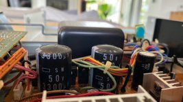
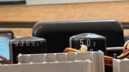
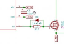
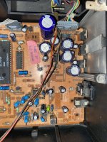
Therefore, seeing that i had a look at the coupling 0.47uF capacitors as well as those resistors (47K for reference but i have them as 68K and 36K)..Tracked those that were related to these first two valves and replaced it all (got new caps & resistors) - guess what - no change to these odd voltages..
I even checked that 100uF capacitor (i have 68uF in my amp so i used new 68uF) and replaced that 15R 0.25W as it looked like a bit cooked - no change.
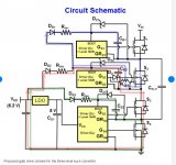
The attached is the schematics and the bits that i checked are circled in red.

So i have run out of ideas and was about to ask for a help here on this forum, just before doing so i thought of moving the valves around again, this time moving around valve nr.2 too as this is the one with the odd control grid voltage but the one that glowed was in socket 1.

Guess what, the odd control grid voltage moves with the valve, that means there is something wrong with that valve 2 or it is still ok but perhaps on its way out.

Obviously, both need replacing for matched pair as far as i know.

So what do you guys think - should i just get a new matched pair and bin them 2 valves? Do i still have to check something in circuitry?

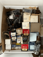
The valves have not seen much of use, i would guess they have had some 50 hours of use (perhaps not even that many) as i do not use the amp very often and bought them couple of years ago when this amp went on fire due to short circuit in one of the output transformers (there is a post about it somewhere here on diyaudio).

I also have JJ EL34 but not using them since apparently EL34s can wreak havoc in this amp.

Out of curiosity, possibly, in future, when my wallet allows it i would like to try some 5881 valves, do you recommend any particular make, like Sovtek or is it again tube rolling game where it all depends on an individual music taste?

Apologies for being long-winded & thanks a lot for reading this.

Attachments

For Sale NIB Markaudio Drivers

Hello! I am trying to raise some money to support my dad, so I am selling some drivers 🙂

Recently I made a trade that on my end netted me a bunch of really nice drivers. The previous (first) owner meant to start a speaker company, but for various reasons ended up liquidating his inventory instead. Since I don't have such lofty ambitions, there are only so many of these drivers that I can reasonably use. Everything listed has never been used in a project, and is as such in mint condition. Everything is enclosed in the box it came with, and includes mounting screws and gaskets. Local sales would be great, but I can ship too. I'm located in Dayton Ohio Here is what I am selling:
Madisound price: $72 plus shipping. My price: $40 plus shipping
One pair MarkAudio CHR-70(A) Generation 3 Black. Madisound price: $72 plus shipping. My price: $40 plus shipping
One pair MarkAudio CHR-70(A) Generation 3 Silver. Madisound price: $72 plus shipping. My price: $40 plus shipping
One pair MarkAudio Alpair 7P (A) Generation 1 Blue. My price: $60 plus shipping SOLD
One pair MarkAudio Pluvia Seven P (A) Blue. Madisound price: $103.60. My price: $55 plus shipping
One pair MarkAudio Pluvia Eleven (A) Generation 1 Grey. Madisound price: $174.20 plus shipping. My price: $95 plus shipping SOLD
One pair MarkAudio CHR-90 Generation 1 Silver. Madisound price: $112 plus shipping. My price: $60 plus shipping

Attachments

  • 20230330_175202.jpg
    20230330_175202.jpg
    502.1 KB · Views: 132
  • 20230330_175249.jpg
    20230330_175249.jpg
    509.1 KB · Views: 117
  • 20230330_180319.jpg
    20230330_180319.jpg
    469.2 KB · Views: 125
  • 20230330_180348.jpg
    20230330_180348.jpg
    495.9 KB · Views: 122
  • 20230330_180604.jpg
    20230330_180604.jpg
    490.1 KB · Views: 123
  • 20230330_180626.jpg
    20230330_180626.jpg
    507.1 KB · Views: 124
  • 20230330_180748.jpg
    20230330_180748.jpg
    482 KB · Views: 129
  • 20230330_180819.jpg
    20230330_180819.jpg
    429.7 KB · Views: 139
  • 20230330_181238.jpg
    20230330_181238.jpg
    534.7 KB · Views: 121
  • 20230330_181323.jpg
    20230330_181323.jpg
    596.2 KB · Views: 119
  • 20230330_181528.jpg
    20230330_181528.jpg
    527.9 KB · Views: 118
  • 20230330_181551.jpg
    20230330_181551.jpg
    499.9 KB · Views: 123
  • 20230330_181800.jpg
    20230330_181800.jpg
    530.9 KB · Views: 116
  • 20230330_181824.jpg
    20230330_181824.jpg
    460.7 KB · Views: 121
  • 20230330_182019.jpg
    20230330_182019.jpg
    515.5 KB · Views: 115
  • 20230330_182056.jpg
    20230330_182056.jpg
    507.6 KB · Views: 116
  • 20230330_182309.jpg
    20230330_182309.jpg
    563.3 KB · Views: 115
  • 20230330_182355.jpg
    20230330_182355.jpg
    397.7 KB · Views: 115
  • 20230330_182618.jpg
    20230330_182618.jpg
    479.9 KB · Views: 126
  • 20230330_182728.jpg
    20230330_182728.jpg
    458.1 KB · Views: 135
Projects by fanatics, for fanatics
Get answers and advice for everyone wanting to learn the art of audio.
Join the Community
507,685
Members
7,884,222
Messages

Filter

Forum Statistics

Threads
406,035
Messages
7,884,222
Members
507,685
Latest member
EvenLouder