Here is a tapped horn design intended for pro sound reinforcement type applications, or any just plain old, really loud music apps that I started working on last July and finally finished the design back at the beginning of March. I worked on this in tandem with the Gjallerhorn. I decided to have the Gjallerhorn built first as it was a larger, more complicated, more expensive and risky design. Since it turned out so well I am feeling rather confident about this one.
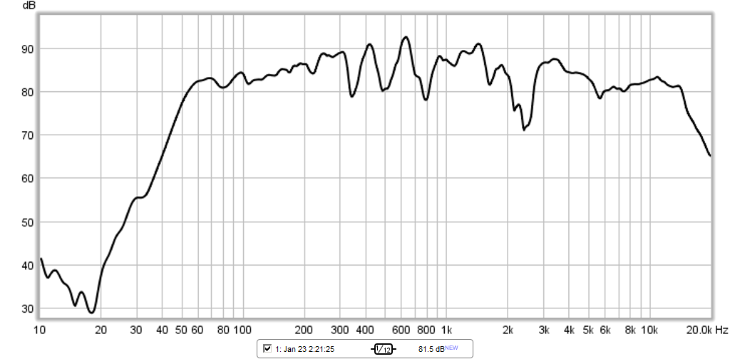
😎 My goals with this design were true 30hz extension with solid useable output to the 25hz range. This is quite a bit lower than the majority of pro bass bins will really reach to despite their ratings. The increasing popularity of down tuned 5 and 6 string bass guitars, bass drops and the prevalance of DnB and Dubstep genres have started to ask for more power than ever from subs in the 25-35hz range. Along with this extension I wanted it to still be able to get quite loud and to retain decent sensitivity. I also decided to use an enclosure form of no larger than 36x36x24" which is large but not out of the ordinary for pro bass bins and comparable in total volume with many double 18" vented subs. A larger 45x45 type of cabinet like the Gjallerhorn or Labsub would've given better efficiency and higher output but these types of cabs are larger and heavier than I want to lug around very often. A pair of these should do most bars or small venues with no problem and 4 should do a good job in a mid sized venue. 2 will fit in the cargo hold of most medium sized suv's.
I already own a pair of B&C 21sw152-4 drivers and Danley has already used them in a couple of tapped horns so it was a no brainer to design around them.
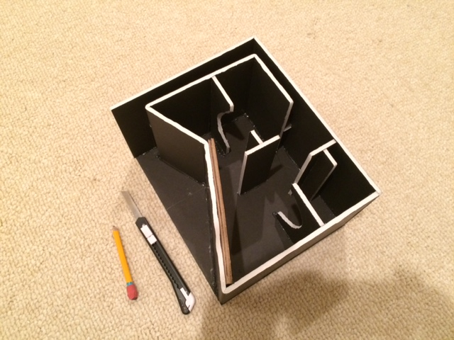
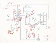
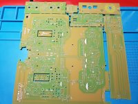
Fast forwarding through about 9 months of design work and revisions here is what the final design will be. I will contract he same cabinet shop that built the Gjallerhorn cabs to do these as well. Unfortunately with everything else going on I don't have the time to build cabs this complicated myself anymore
🙁. Besides I could never deliver the build quality that the professionals can.
BTW Thanks to Soho54 for being my sanity checker on this cab design.
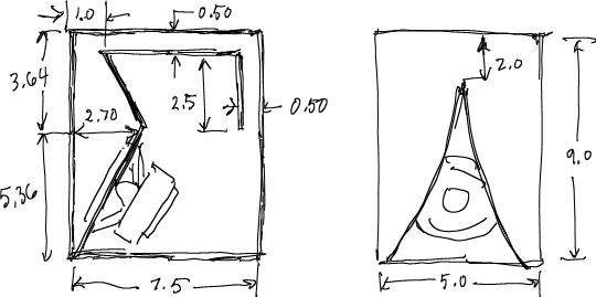
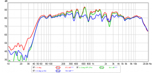
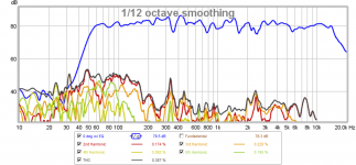
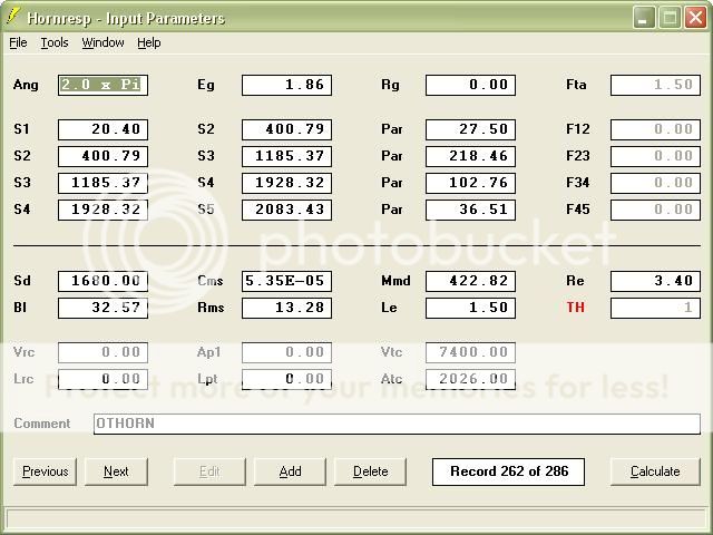
Here is the HornResponse and Akabak input data for simulating the cab. This one was also designed in Akabak working backwards from the cabinet size and best fold that would fit in the cab and achieve the right low corner instead of the other way around. I have found this works much easier for me than coming up with a pretty simulation and trying to fold and cram it into a workable cabinet while maintaining the parameters. Once again I use Akabak since there were so many folds, different expansion rates and corners involved. Amazingly the much simpler HR simulation that approximates the final Akabak one is very close. The differences are there but quite small. Not worth worrying about for most people unless you are a stickler like me who is worried about accuracy to the nth degree. Anyway here are the inputs.
NOTE: If you wish to model 18" drivers in this cabinet you should change the value of VTC to 4000 and the ATC value to 1465
HR
Akabak script
|COMMENT: OTHORN B&C 21SW152-4 30hz TH 36"x36"x24" revised 030411 completion(Driver restricts horn by approximately 517cm2 at S32)
|========================================================================================================
|REQUIRED AKABAK SETTINGS:
|File > Preferences > Physical system constants:
|Sound velocity c = 344m/s
|Medium density rho = 1.205kg/m3
|Sum > Acoustic power:
|Frequency range = 10Hz to 20kHz
|Points = 533
|Input voltage = 1.86V rms
|Integration = 2Pi-sr
|Integration steps = 1 degree ... 1 degree
|Integration method = Cross
|========================================================================================================
Def_Const |
{
|Length, area and volume values converted to metres, square metres and cubic metres:
S1 = 20.397216e-4; |Horn segment 1 throat area (sq cm)
S2 = 400.79072e-4; |Horn segment 1 mouth area and horn segment 2 throat area (sq cm)
S3 = 480.93721e-4; |Horn segment 2 mouth area and horn segment 3 throat area (sq cm)
S4 = 490.40735e-4; |Horn segment 3 mouth area and horn segment 4 throat area (sq cm)
S5 = 499.87748e-4; |Horn segment 4 mouth area and horn segment 5 throat area (sq cm)
S6 = 503.41786e-4; |Horn segment 5 mouth area and horn segment 6 throat area (sq cm)
S7 = 752.67183e-4; |Horn segment 6 mouth area and horn segment 7 throat area (sq cm)
S8 = 525.374e-4; |Horn segment 7 mouth area and horn segment 8 throat area (sq cm)
S9 = 672.07369e-4; |Horn segment 8 mouth area and horn segment 9 throat area (sq cm)
S10 = 1003.4701e-4; |Horn segment 9 mouth area and horn segment 10 throat area (sq cm)
S11 = 706.47214e-4; |Horn segment 10 mouth area and horn segment 11 throat area (sq cm)
S12 = 710.68271e-4; |Horn segment 11 mouth area and horn segment 12 throat area (sq cm)
S13 = 1011.4833e-4; |Horn segment 12 mouth area and horn segment 13 throat area (sq cm)
S14 = 744.03216e-4; |Horn segment 13 mouth area and horn segment 14 throat area (sq cm)
S15 = 827.70445e-4; |Horn segment 14 mouth area and horn segment 15 throat area (sq cm)
S16 = 1148.9606e-4; |Horn segment 15 mouth area and horn segment 16 throat area (sq cm)
S17 = 850.19967e-4; |Horn segment 16 mouth area and horn segment 17 throat area (sq cm)
S18 = 852.58905e-4; |Horn segment 17 mouth area and horn segment 18 throat area (sq cm)
S19 = 1222.0554e-4; |Horn segment 18 mouth area and horn segment 19 throat area (sq cm)
S20 = 876.8326e-4; |Horn segment 19 mouth area and horn segment 20 throat area (sq cm)
S21 = 434.06586e-4; |Horn segment 20 mouth area and horn segment 21a throat area (sq cm)
S22 = 572.31875e-4; |Horn segment 21a mouth area and horn segment 22a throat area (sq cm)|
S23 = 1185.3696e-4; |Horn segment 22a mouth area and horn segment 23 throat area (sq cm)
S24 = 1724.8322e-4; |Horn segment 23 mouth area and horn segment 24 throat area (sq cm)
S25 = 1255.2883e-4; |Horn segment 24 mouth area and horn segment 25 throat area (sq cm)
S26 = 619.44195e-4; |Horn segment 25 mouth area and horn segment 26a throat area (sq cm)|
S27 = 680.54455e-4; |Horn segment 26a mouth area and horn segment 27a throat area (sq cm)|
S28 = 1400.7642e-4; |Horn segment 27a mouth area and horn segment 28 throat area (sq cm)
S29 = 2279.1994e-4; |Horn segment 28 mouth area and horn segment 29 throat area (sq cm)
S30 = 1799.9231e-4; |Horn segment 29 mouth area and horn segment 30 throat area (sq cm)
S31 = 1805.1536e-4; |Horn segment 30 mouth area and horn segment 31 throat area (sq cm)
S32 = 1411.3236e-4; |Horn segment 31 mouth area and horn segment 32 throat area (sq cm)/(1411.3236cm restricted by driver (estimated),1928.3236cm ignoring driver in path)
S33 = 2043.1017e-4; |Horn segment 32 mouth area and horn segment 33 throat area (sq cm)
S34 = 2057.0009e-4; |Horn segment 33 mouth area and horn segment 34 throat area (sq cm)
S35 = 2260.638e-4; |Horn segment 34 mouth area (sq cm)
L12 = 27.504644e-2; |Horn segment 1 axial length (cm)
L23 = 27.258518e-2; |Horn segment 2 axial length (cm)
L34 = 3.070098e-2; |Horn segment 3 axial length (cm)
L45 = 3.355594e-2; |Horn segment 4 axial length (cm)
L56 = 1.203198e-2; |Horn segment 5 axial length (cm)
L67 = 3.625088e-2; |Horn segment 6 axial length (cm)
L78 = 3.781298e-2; |Horn segment 7 axial length (cm)
L89 = 41.853612e-2; |Horn segment 8 axial length (cm)
L910 = 4.81838e-2; |Horn segment 9 axial length (cm)
L1011 = 5.029708e-2; |Horn segment 10 axial length (cm)
L1112 = 1.20142e-2; |Horn segment 11 axial length (cm)
L1213 = 4.740656e-2; |Horn segment 12 axial length (cm)
L1314 = 4.877562e-2; |Horn segment 13 axial length (cm)
L1415 = 37.930582e-2; |Horn segment 14 axial length (cm)
L1516 = 5.453888e-2; |Horn segment 15 axial length (cm)
L1617 = 5.582412e-2; |Horn segment 16 axial length (cm)
L1718 = 1.20269e-2; |Horn segment 17 axial length (cm)
L1819 = 5.869432e-2; |Horn segment 18 axial length (cm)
L1920 = 6.282436e-2; |Horn segment 19 axial length (cm)
L2021 = 1.371346e-2; |Horn segment 20 axial length (cm)
L2122 = 46.972982e-2; |Horn segment 21a axial length (cm)
L2223 = 2.97434e-2; |Horn segment 22 axial length (cm)
L2324 = 7.91972e-2; |Horn segment 23 axial length (cm)
L2425 = 8.488172e-2; |Horn segment 24 axial length (cm)
L2526 = 2.246376e-2; |Horn segment 25 axial length (cm)
L2627 = 30.794452e-2; |Horn segment 26a axial length (cm)
L2728 = 2.872232e-2; |Horn segment 27 axial length (cm)
L2829 = 11.00836e-2; |Horn segment 28 axial length (cm)
L2930 = 10.296144e-2; |Horn segment 29 axial length (cm)
L3031 = 1.199134e-2; |Horn segment 30 axial length (cm)
L3132 = 27.93238e-2; |Horn segment 31 axial length (cm)
L3233 = 26.647902e-2; |Horn segment 32 axial length (cm)
L3334 = 3.189478e-2; |Horn segment 33 axial length (cm)
L3435 = 6.672834e-2; |Horn segment 34 axial length (cm)
Vtc = 7400e-6; |Throat chamber volume (cc)(Estimated)
Atc = 2026.00e-4; |Throat chamber cross-sectional area (sq cm) (Estimated)
|Parameter Conversions:
Sd = 1680.00e-4; |Diaphragm area (sq cm)
Ltc = Vtc / Atc;
}
|========================================================================================================
|Network node numbers for this tapped horn system:
| 0-Voltage-1
| |
| -Chamber-5-Driver---
| | |
|8-Segment-9-Segment-10-Segment-11-Segment-12-Segment-13-Segment-14-Segment-15-Segment-16-Segment-17-Segment-18-Segment-19-Segment-20-Segment-21-Segment-22-Segment-23-Segment-24-Segment-25-Segment-26-Segment-27-Segment-28-Segment-29-Segment-30-Segment-31-Segment-32-Segment-33-Segment-34-Segment-35-Segment-36-Segment-37-Segment-38-Segment-39-Segment-40-Segment-41-Segment-42-Radiator
|========================================================================================================
Def_Driver 'Driver'
Sd=1680.00cm2
Bl=32.57Tm
Cms=5.35E-05m/N
Rms=13.28Ns/m
fs=32.0001Hz |Mmd = 422.82g not recognised by AkAbak, fs calculated and used instead
Le=1.50mH
Re=3.40ohm
ExpoLe=1
System 'System'
Driver Def='Driver''Driver'
Node=1=0=5=39
Duct 'Throat chamber'
Node=5=9
SD={Atc}
Len={Ltc}
Visc=0
Waveguide 'Segment 1'
Node=8=9
STh={S1}
SMo={S2}
Len={L12}
Waveguide 'Segment 2'
Node=9=10
STh={S2}
SMo={S3}
Len={L23}
Waveguide 'Segment 3'
Node=10=11
STh={S3}
SMo={S4}
Len={L34}
Waveguide 'Segment 4'
Node=11=12
STh={S4}
SMo={S5}
Len={L45}
Waveguide 'Segment 5'
Node=12=13
STh={S5}
SMo={S6}
Len={L56}
Waveguide 'Segment 6'
Node=13=14
STh={S6}
SMo={S7}
Len={L67}
Waveguide 'Segment 7'
Node=15=14
STh={S8}
SMo={S7}
Len={L78}
Waveguide 'Segment 8'
Node=15=16
STh={S8}
SMo={S9}
Len={L89}
Waveguide 'Segment 9'
Node=16=17
STh={S9}
SMo={S10}
Len={L910}
Waveguide 'Segment 10'
Node=18=17
STh={S11}
SMo={S10}
Len={L1011}
Waveguide 'Segment 11'
Node=18=19
STh={S11}
SMo={S12}
Len={L1112}
Waveguide 'Segment 12'
Node=19=20
STh={S12}
SMo={S13}
Len={L1213}
Waveguide 'Segment 13'
Node=21=20
STh={S14}
SMo={S13}
Len={L1314}
Waveguide 'Segment 14'
Node=21=22
STh={S14}
SMo={S15}
Len={L1415}
Waveguide 'Segment 15'
Node=22=23
STh={S15}
SMo={S16}
Len={L1516}
Waveguide 'Segment 16'
Node=24=23
STh={S17}
SMo={S16}
Len={L1617}
Waveguide 'Segment 17'
Node=24=25
STh={S17}
SMo={S18}
Len={L1718}
Waveguide 'Segment 18'
Node=25=26
STh={S18}
SMo={S19}
Len={L1819}
Waveguide 'Segment 19'
Node=27=26
STh={S20}
SMo={S19}
Len={L1920}
Waveguide 'Segment 20'
Node=28=27
STh={S21}
SMo={S20}
Len={L2021}
Waveguide 'Segment 21'
Node=28=29
STh={S21}
SMo={S22}
Len={L2122}
Waveguide 'Segment 21b'
Node=28=29
STh={S21}
SMo={S22}
Len={L2122}
Waveguide 'Segment 22'
Node=29=30
STh={S22}
SMo={S23}
Len={L2223}
Waveguide 'Segment 23'
Node=30=31
STh={S23}
SMo={S24}
Len={L2324}
Waveguide 'Segment 24'
Node=32=31
STh={S25}
SMo={S24}
Len={L2425}
Waveguide 'Segment 25'
Node=33=32
STh={S26}
SMo={S25}
Len={L2526}
Waveguide 'Segment 26'
Node=33=34
STh={S26}
SMo={S27}
Len={L2627}
Waveguide 'Segment 26b'
Node=33=34
STh={S26}
SMo={S27}
Len={L2627}
Waveguide 'Segment 27'
Node=34=35
STh={S27}
SMo={S28}
Len={L2728}
Waveguide 'Segment 28'
Node=36=35
STh={S28}
SMo={S29}
Len={L2829}
Waveguide 'Segment 29'
Node=36=37
STh={S30}
SMo={S29}
Len={L2930}
Waveguide 'Segment 30'
Node=37=38
STh={S30}
SMo={S31}
Len={L3031}
Waveguide 'Segment 31'
Node=39=38
STh={S32}
SMo={S31}
Len={L3132}
Waveguide 'Segment 32'
Node=39=40
STh={S32}
SMo={S33}
Len={L3233}
Waveguide 'Segment 33'
Node=40=41
STh={S33}
SMo={S34}
Len={L3334}
Waveguide 'Segment 34'
Node=41=42
STh={S34}
SMo={S35}
Len={L3435}
Radiator 'Horn mouth'
Node=42
SD={S35}


 Single thread combined from others in Vendor's Bazaar.
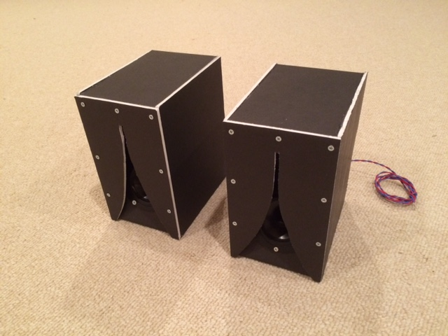


