Hi Sony VFET amp experts, I am rebuilding my Sony ta 4650 VFET amp. After replacing the old capacitors , zener diode 1T43M with with a 7.5v zener diode , replacing all other diodes I am getting +-53vdc on the 2 large 47,000uf/50v caps instead of -+45vdc what might be the cause of this high voltage , your kind help is greatly appreciated . Thanks
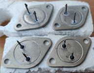
Hi all, I have recently acquired 6 pairs of the above transistors. Can anyone please help me with a schematic to suit theses transistors? Pulled from a Yamaha amp. Ive googled myself silly and have found nothing.
Trying to repair a faulty Dali Basis 100 sub-woofer. To my surprise the Dali support decline to share schematics or service manual, even for this out of date product. Anyone have access to it and can share, or already done some reverse engineering?
For those using a digital front end I’m curious what DAC you’re using. I have all my music on my MAC mini and am currently using a USB streamer from HRT to handle conversion duties. This is the only dac I’ve ever had and while functional I’d like to change to a stand alone separate. I don’t need portability but really want to improve front end. The dac seems the best place to start. I’m just about finished building an F6 and am also considering building a B1 preamp. My system is barebones as I’m currently using a Marantz receiver and a pair of diy single driver speakers. Mostly I listen via pandora and a Bluetooth dongle with my amp.
Not great but I like Pandora and using it through my iPhone is convenient. I rarely use my Mac but would like to experience better sound as I think my speakers are capable of much more. I’m considering several sacs: Denafrips, Schitt , RME, and maybe Topping on the hifi side and maybe even Convert 2 or a crane song Solaris but those pro audio, studio types that while intriguing probably not appropriate? Initially I thought I’d like to stay under $1000 but that may not be enough. It’s an impossible task to audition hifi equipment. I have to rely on manufacturers that have a free return policy, an in home test so to say. Also considered getting a decent record player but I’ve no library of vinyl so would be starting from scratch on that end. Thanks for reading and please offer your thoughts
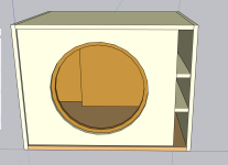
How long should the port be for each sub for the best response?
The generic plans I found online specify back port panel and the port bottom panel to both be 20.75" x 22.5
I will be running both into a MiniDSP with Dirac after, if that changes anything
I ran a couple of simulations using WinISD for a sealed sub, but ported is just out of my league
Since a capacitor is made of a dielectric and plates and there are several types of capacitors differentiated by their dielectric, I would like to ask which types are suitable for audio signal processing? I do not wish that this thread transforms into claims not based on the science of dielectrics and capacitor construction.
Hi,
A few years ago I was building a music streamer based on a pc and TDA1541 board.
Changing the original switching power supply to linear one made a great improvement.
Splitting to two power supply - one for the DAC and one for the computer helped a lot!
Upgrading the OPAMP of the DAC to a higher quality ones mad a great improvement.
The sound is great, but a little "too compressed" as opposed to my DIY turntable. And here goes my question: do you think that building a tube-output stage instead of the om-amps can help? I rely love the sound of the TDA1541, and, yes, I know it is a very old cheep. 🙂 I'm building a new streamer, based on a Raspberry Pi, and there will be much less wires in the new version... Is it time for tube output stage?
Any advice or direction to a proper kit / schematics will be highly appreciated.
Now, I have a few questions but I will start with this one.
When it came to wiring this set-up, I had no diagram and the local PA "guru" of the group advised me to
"wire the tweeters in series.... Parallel to the cone"
So I did.... But ever since then every configuration of one driver and two tweeters I have seen are not wired this way.
Is my system wired correctly.....?
I am currently re-building this box but obviously because of the cut-outs I cannot really change the tweeters.
I am reading lots of conflicting information online about resistor values and crossover circuits for piezos but again,
all for just one driver and one tweeter.
I would like to quieten these screamers down a few dB's..... Would anyone have the proper schematic or some sound advice for this
seemingly unusual configuration……?
Hello and Happy New Year! Anything started when a horrible noise came out of my loudspeakers when playing Randori, a CD by Nik Baertsch via the preamp SAE 2100L, AUX1 input, I actually thought it was the power amp, so I connected the CD player straight to the power amp, same CD track ,,, no noise. Back to the preamp, same CD track, noise again. Well, to be short, the preamp looked faulty, In the AUX area. This meant a lot of disassembling, to reach the Line Amp pcb. Of course, Line Amp 17-0437 schematics were unfindable. I decided to reverse engineer the pcb in order to understand a little more. Now I have a schematic. The ICs are NE5534. Surprise! The compensation capacitors are connected between pins 1 and 5 instead of between pins 5 and 8. QUESTIONS: can anyone imagine why. please? Can anyone foresee what could happen? Were NE5534 the original ICs? I'm scratching my empty head, wondering and resultlessly... Thanks in advance, should anyone be willing to remark. Kind regards. Alberto
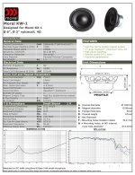
Came across what appears to be a sleeper Morel bass-mid sold by PE. It looks very good based on specs and cost. The higher Qts makes it suitable for a sealed box and also as a dedicated midbass. FR appears smooth to 5k, 86dB sensitivity and 4 ohm VC. Its apparently a custom design proprietary driver sold only through PE. Hopefully the motor has better HD performance than most other lower end Morels suffer from.
are somebody familiar with AK4137 in serial mode?
There are some things, which I cannot understand from the datasheet.
Register 03h have 2 bits: PCMFSO1,PCMFSO0, what this bits doing?
PCMFSO1, PCMFSO0: PCM Output Sampling Freq Frequency Select→ Filter Select in DSD input mode
00 : 44.1KHz or 48KHz (Cut Off 20KHz) (default)
01 : 88.2KHz or 96KHz (Cut Off 40KHz)
10 : 176.4KHz or 192KHz (Cut Off 80KHz)
11 : 384KHz or more (Cut Off 100KHz)
But when i change these bits in PCM mode, nothing happens.
The only way to change PCM Out Fs is to change the clock frequency or to change CM3...CM0 pins.
In DSD mode, with CM3..0=0000 and clock=11.289MHz I can change the output as DSD64/DSD128/DSD256 by DSDOFS1 and DSDOFS0 in 04h register, but in PCM mode, out Fs = 44.1 kHz and not depend of PCMFSOx.
I can change it by CM3..0 pins, bit I suppose that everything can be changed in software.
I hope this post finds you well. I'm reaching out today as I'm currently grappling with a rather tricky issue concerning my Pioneer VSX-921 amplifier. I've recently encountered the dreaded UE22 error code, and after consulting with several repair professionals, the proposed repair bill is reaching double the cost of the amplifier itself.
After doing some research, it appears that the issue lies with the "Texas Instruments DTS chip." My goal today is to seek your expertise and gather experiences regarding the feasibility of fixing this myself. Fortunately, I possess soldering and component replacement skills, but I am aware that the level of complexity can vary.
So, I would like to inquire if any of you have attempted a successful self-replacement of this chip. Are there any tips, tricks, or precautions you could share? I am open to any insights that might aid me in this endeavor.
Furthermore, if you have suggestions on where I could procure the "Texas Instruments DTS chip" or even the entire board it sits on, I would be immensely grateful. Could you provide an estimate of the price range I might expect?
I am confident that together, by sharing our knowledge and experiences, we could find an affordable and practical solution to address this issue. Thank you in advance for your invaluable assistance!
Another point: if you have the latest firmaware version I would be luck if you share it with me.
I'm looking at some of the parts I've accumulated and stored and it's time to get honest about what I need/want/will build. I'll update this I go through things.
Added L20D “kit” on Dec 15th.
Big 10uF 2000V caps - $30 pair
GE 4uF 2000V caps - $20 pair
Payment via Paypal. Shipping via USPS.
Sold items here; Heathkit W5M (pending). - $400/pair With the 16093 peerless outputs. I was told all the iron is good, but I haven't tested it. One of the monos has been disassembled. Please see pictures.
JBL 2482 - $500/pair. Well loved on the outside, Great original diaphragms. Drivers are 23lbs each.
VFET lottery amplifier. $600 2sj28 version with signed papa boards. I won, then built, this absolutely wonderful amplifier but for the last year it's been set aside for other amplifiers.
JBL 2410 - $200/pair. In good appearance, original diaphragms.
Iwata horns (sold) and
Pair of standard Betsy in Caintuck baffle (no pictures yet). Message me with offers.
Pair of AlNiCo Betsy in some really beautiful RESO cabinets built by EJFud. These are big and beautiful, local sale in Minnesota only.
Mini Aleph boards. Two stereo sets with power supply board. I have one of these in my shop and love it, but I don’t need 4 more channels. $25
L’amp package; pair of 2sk82 from Acronman, SumR 400VA transformer specced for L’amp, pair of 6800uF supertune caps, and a pair of Hammond 159ZA (300mH, 6ohm, 1A) inductors. -$200
841 /VT-51 tubes $200 for all 4pcs. NOS aside from being tested.
Audial AYA II 2014 board with 2pcs TDA1541 Taiwan (purchased in Holland). $150
PD AlephJ X PCB with parts kit for standard stereo. Each PCB will give you one X’d channel. Parts kit is for standard AlephJ. Comes with matched J108 jfets. $100.
I had an amp project go a different direction and I'm selling a few things I won't be using. If you buy multiple things I can figure out a small combined shipping discount.
Mini Dissipante 3U 330mm x 200mm - 10mm black front plate, new and in the shrink wrap. Looking for $115 shipped CONUS. SOLD
Avel Lindberg Y236505 - 160VA 30v+30v toroidal transformer, also unused. Includes mounting hardware and EMI band. Looking for $40 shipped. Login to view embedded media Hammond 1458VC3B 6x3x6 Steel Vented Case - unused, looking for $25 shipped. Login to view embedded media
Paypal G&S preferred. It's been a long time since I posted here so if you'd like feedback or verification some other way, let me know! I have Heatware feedback, eBay, Head-Fi, etc.
I put J2 and M2 in the same chassis using talema encaps 2x18V 225VA, locate them on each corner of the room intended for monoblock. with neutrik powercon, I can choose J2/M2 to play. but I rarely use it because SIT L'Amp mostly used for fullrange driver
with 3way dsp project, I'm using 2 class ab amplifiers for midrange and tweeter operating above 200Hz.
if i want to use this unused J2/M2 for mid+tweeter in 3way speaker, just wondering is it wise to power both J2 and M2 with only 225VA toroid? will it make toroid become too hot or both amplifier got less amperage? not sure which one or both will happen
Hello everyone, I have a basic LM1875 amplifier made with a basic PCB from AliExpress. I am really not getting any bass from the speakers, but the speakers I use are satellite Logitech speakers. Is the reason for no bass is that I only have treble speakers? If so, can I hear some more when I connect a fullrange speaker? Or is my amplifier just not enough? I have the PCB linked below, and keep in mind that I am not a basshead, but I really do not hear anything below 250hz from these speakers. Thanks!
Having realized my dream of designing and building a 3-Way, Coaxial Compression Driver, and Horn speaker capable of playing down to 300Hz by 112.5dB, paired with a Closed Bass 15” (101 dB), I now have the opportunity to take my hobby more seriously. Previously, I was building DIY speakers based on blueprints from the internet.
I recently acquired funds, allowing me to delve deeper into the world of amplifiers. Despite having zero knowledge about amps initially, I've gradually gained understanding. My preference is to drive these speakers with a tube amplifier. I have an DSP + Active Crossover + Preamp+DAC Allinone Solution from the German high-end horn manufacturer Hornsolution with a Nadja Board.
Through some coincidences, I obtained a pair of Quad II with original tubes, together with a DIYTube Preamp (1 Phono (mm), 4 Line 1 Tape In). My plan is to implement a passive crossover for the coaxial compression driver, enabling me to drive them with one tube amp. I intend to connect the amp to the Hornsolution Nadja, and have it only cut the frequencies below 300Hz, and use the Tube PreAmp for the CD Player/TT attached to the Nadja.
Now, my questions:
A) For the bass, which will receive a low pass filter for the crossover, I'm uncertain about the right amp. Should I go for a Tube or Class A or D with more wattage?
B ) I've attached a picture of the amp. Can you confirm if the amp is wired to 8 ohms? What's your initial impression of its condition?
C) The preamp was inherited, and the person doesn't know much about it. Can someone assess the quality/value of the preamp? Was it worth the 300€?
D) What are your overall thoughts on my plan? Does it make sense?
Hey all! Gen Xer here (I do remember 8 track lol). Now that I’ve recently acquired a mint Sansui AU/TU-717, (with original boxes no less) to go with my Snell Type-D loudspeakers, I’m going down the rabbit hole on building speaker cables. Looking to find a downloadable copy of “the supercables cookbook” by Allen Wright. I don’t see it on their website so if anyone knows where I can purchase one I’d much appreciate it!
Can someone tell me which resistors in this diagram are responsible for setting the gain? This is a LPF using t072 opamps. It would be great to know exactly which caps and resistors are setting the lpf. I have been struggling to read opamp diagrams and translate them to what I'm looking at on the PCB itself.
Hi there. Trying to fix my Marantz NR1607. Thing got stuck in “update…retry” loop and, being extremely frustrated, selected the “force usb” firmware update option in “special modes.” Now I’m stuck with a truly bricked receiver since I don’t have the firmware.
So I’m hoping that someone can help me out if they have the US version of the firmware for the NR1607 (or any of the NR16** series).
Ps - I’m stuck on a remote island (Kauai) in the middle of the pacific, so taking this to a service center just isn’t going to happen.
I searched around and saw it mentioned that you can get better grommets to make the knobs smoother from Ace Hardware. Does anyone have a link to the correct grommets for purchase in the USA? Or instructions on what to look for at the hardware store?
Hello all
My name is Randy. I have been floating around the forum for a while. Recently, I started work on a pair of desktop speakers using drivers without proper specs. Only relevant info supplied were power, dimensions and a response down to 32hz. I asked for help on the forum, and a number of folks helped me work out some viable options with enclosures to try these out with. One of the directions was a TL of around 20 odd litres. Along the discussions, I ran various iterations of the model in CAD to visualise what the work file would look like. During the course, I noticed that I had created a template to allow these quick changes and its implications. This template would not have been possible without folks taking an interest and educating freely and being generous with their time and expertise. I found this to be the case with both commercial and enthusiast members of this forum
Allow me to share this template back to everyone. I'll be glad if this is of use to you to either easily make boxes for messing around or develop to your commercial boxes. The template will be able to assist you to create not only sophisticated speaker boxes but anything really. I will be using this for making a tube power amplifier chassis too
I call this particular implementation of the stepped tunnels the "Bassinga Flatwounds". Please mention this name with your work, so people may treat my misconceptions kindly 🙂
The system
This is based around a 3D model using FreeCAD. The template allows easy manipulation of all fields to a novice with CAD to alter required areas. Base model is for a 6.5" Pioneer coaxial driver that I am set to trail. The model can be scaled down and 3D printed or CNC'ed for tiny format speakers. My print bed is 40 x 40 x 40 cm, so I have the real estate to print my full box should I wish. This does take a while even with a 1 mm nozzle and fast settings, as well as material costs. This template will help solve these issues and I will show a tutorial in a future instalment once I am ready to proceed with my desktop TL build
For the moment, I am curious to sees how it prints. I have another pair of unknown 3" full range speakers with the only info being 30wrms and 8 ohms printed on the back. This will be a test for the comprehensive tuning abilities that my CAD template offers pre- and post-printing. This is for another future instalment
Template features
Full or semi prints
Model is converted to a building jig that ends up as decorative trim for boxes too large to print whole
Simple build process that can used already prepared flat material like finished floor planks as well as foam and foam core and the usual ply and MDF. Just about any suitable material can be used
The jig takes care of all the assembly work and removes the need for making wooden box edges look good
Some glue, a screwdriver and a drill are all the tools needed to assemble the box to result in a commercial level finish
Speaker workshops can adjust to their requirements and sell kits (please mention cab name)
Adjustments can be made to the template as well as to already made boxes, the tunnels can be inserted with all sorts of things to change tapers and such as well as stuffing due to the easy access nature inherent in the design
In the next instalment, I will show how to navigate the template and carry out changes. Do not hesitate to point out any mistakes. If any CAD sharks want to assist, go for it 😀
The zip file contains the FreeCAD 3D template
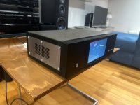
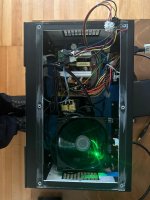
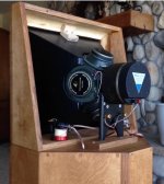
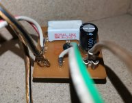
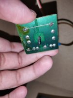
Hello everyone, simple question, would this kind of build generate distortion or noise in the signal which feeds the (class D) amplifier (can dirty noise creep back from the vu meter board, which has a small amplifier, and a noisy 12v SMPS)?
My basic knowledge of electricity tells me "no", but I would like an expert advice from people more versed in electronics and signal processing 🙂
Last week I joined two forums that concern DIY audio. I became a CONTRIBUTING member of both right from the start. I had never belonged to ANY forum before, so I tried to be careful as I made my first post on that other forum, not to do anything that might upset anybody. I believe in being courteous. My younger brother who has a lot of "social media" experience(I have none) told me that I might be disappointed at the results I would get, the experience I might have, but I decided to give it a try anyway. I was excited when my first post on the other forum got a number of replies and I hurried to read them. I quickly found exactly what my brother had referred to as I received not ONE suggestion to my query, but instead half a dozen complaints about how I composed my post. I had forgotten that the world is full of people who have nothing better to do than spend their time trolling the world, looking for others to vent their petty and negative attitudes on. I have now BLOWN OFF that other forum and blocked any further contact by their members as I have no time for those who waste MY time. I will try HERE in the hopes that this forum is not populated by people of that ILK.
I would like advice concerning good sources of schematics for the vacuum tube equipment, especially amplifiers of all types, that I am working on as a retirement hobby/sideline. I have been doing some modification work with vintage/old Hi-Fi, organ, and even Ham radio amplifier equipment attempting to turn them into guitar and bass amplifiers. I am tired of YouTube videos that only sometimes deliver usable results as a "go to" source of information and haven't had much luck finding schematics, for much of the "stuff" that I buy on ebay and other places to work on. I have not tried paying for schematics on those places that offer them for a fee YET, as they usually involve downloading some browser extension that I am just not sure about. However, I am not against trying that IF somebody here can recommend one that is legit with a good selection. I HAVE tried a few free aquisition sites but have been rather disappointed, with perhaps a 30% success rate. Before anybody suggests that I really shouldn't need one to work on any of the "should be familiar" circuits, like the famous Williamson or Dynaco circuits.....please don't! I have not yet educated myself on those circuits that ARE famous or should be familiar. I have work to do before I DIE, and must learn these things "on the fly". I AM reading/studying about these topics as I have time for. I purchased the Radiotron's Designer Handbook 4th. edition, the RCA Receiving Tube Manual, The Art of Electronics by Horowitz and Hill, and about $1,000 worth of other textbooks and reference books to read in my "spare time" so I am not neglecting my education while looking for an easy way out.
SO, if anybody can help me out with suggestions about schematics, I would really appreciate it and I may post further here. Perhaps I can even help somebody here with some useful information, but I wouldn't hold my breath there. My background is in avionics not audio. I am a musician who has tinkered with the equipment I have played and loved since the late '70's and am intent on doing more with it. However, I won't spend one minutes time on those who HAVE the time to complain in type over things that just shouldn't mean a "darned"! I payed right up front for USEFUL interaction here, but I will BLOCK this forum just like the other one, and write off my cash before taking a beating over what I ask for, or my "bad grammar" for that matter. Oh, I am NOT thin skinned either. I just have no tolerance for the ridiculous. Thanks for any HELPFUL replies, dimwitt...I mean watt.
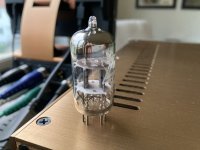
I just bought a pair of NEC 12R-LL3 tubes, manufactured in 1960, under the impression from the listing that they are a Japan version of 12AU7. Now I'm less sure, not having found much information on them at all, and what I found seemed a bit contradictory. I was going to roll these into a Kingko 101 amp in place of its stock pair of 12AU7s. Does anyone know about these? I suppose caution is advised unless I'm sure they're suitable. Which I'm not, at the moment.
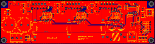
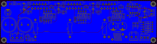
It is not the best practice to parallel amplifiers like this, but I went for it anyways just for fun! 🙂
Noise gain is 10 V/V
Signal gain is 20 V/V
It is essential to use 0.1% feedback resistors:
it will improve CMRR as each LM3886 acts as a difference amp
it will match the gain for all three ICs - which in turn creates less standing current in output ballast resistors.
Input stage is taken directly from Bruno Putzeys article The G Word. It is [three chip instrumentation amplifier]s' first stage that sets the gain using three resistors in the feedback loop of LM4562. Note that load resistance for LM4562 are three 4K resistors in parallel that equal to 1.333K.
I put a set of ALPS heads in my CT-F1250, to replace the old worn heads. Well, now I'm having a problem adjusting the bias. I've adjusted the azimuth properly and the playback levels and EQ, and that's all peachy. The problem is bias adjustment.
When recording a tape, I change the bias signal generator knob to the bias setting. The deck goes into mono mode, and I adjust the right channel bias setting until the arrows are both lit. Then I record a 3000hz signal from the line input... and the left channel cannot go high enough before running out of potentiometer. The right channel still has a third of its adjustment range left, but the left channel is right at the end and can't go any higher. This means the left channel is under-biased. This is the case for STD, FeCr, and Cr02 tapes. (I don't have metal tapes to test with). Since that left channel is under-biased, anything recorded on the left channel is at significantly lower volume. Which is not fun 🙁
What would be causing this? I've already checked for tape skew and tape path problems...
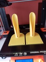
After acquiring a Karslon K15 clone, I got inspired by Freddi to try the K-Tube with a 1" compression driver. Since the orginals are very rare, I made my own with the help of Fusion360 and a 3D printer. I have the first test pair printed. In the attachment, there is the STL model. I am looking forward to trying them out, I hope to find some time during the weekend🙂
I have built some I2S stuff, DSP circuits, DAC out etc. over the years, but I have never had any equipment to measure quality details such as phase jitter.
I would like to ask for suggestions of reasonably priced equipment but good enough quality for measuring phase jitter.
Thank you in advance.
Hi!
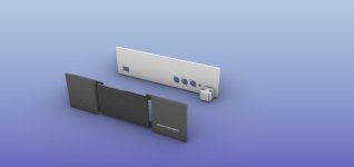
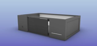
I am building a quite beefy mains filter with 5 outlets. There isn't a switch or anything DC and it's all 230V passing through.
Although it's a more or less passive thing, adding a LED indicator (ideally one per mains out, maybe even indicating wether it's active or not if this does not mean adding sensing devices etc.) would be nice.
Been searching the web and am not really satisfied, so I come here to ask:
Do you know how I could do it or where I could have a look/get directions or a clue?
Thanks...
[edit: The jig will be quite similar to the one uploaded, same filters, similar layout]
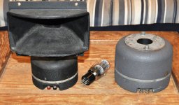
Had a bit of a disaster recently, hoping for some advice. I've recently built a copy of a Yuichi A290 and had it fitted with the JBL 2446H. It was working well and was sounding really good until one of the channels of my amps gave up out of the blue. This channel was powering the JBL and as the amp was significantly overpowered for the speaker I jumped to the conclusion that I'd blown the driver and took it apart to examine the voice coil / diaphragm.
It's only after significant further testing that I realised it was the channel on my amp (although no idea why that's blown...). I've put the JBL back together but the sound has significantly degraded and there's quite severe crackling. Does anybody have any idea what I could have done to the driver? I'm using a test tone to re-install the diaphragm and making sure of a pure tone whilst I do so, but the sound still lacks when i play music through it, especially at higher volumes.
Any help would be really appreciated, have unfortunately had to cancel plans to use my system for NYE... Terrible timing.
Hi, I’ve just purchased an APM2 board to provide DSP functions between a preamp and power amp going in an active loudspeaker. I’ve worked on several projects before with SigmaStudio and Sure / Dayton ADAU1701 based boards before with success however the APM2 doesn’t seem to be behaving as I would expect. Picture shows test setup
With power connected I hear the input signal on the speaker from AD0 connection (also from AD1). I expected this as the board ships with a program already loaded, howeverPOTS d the on’t do anything which suggests the default program on the APM2 is not working.
With power off and the ICP programmer disconnected I still hear audio through AD0 connection – even though the board is not powered up. I wouldn't expect to hear anything as the unit isn't powered. (The audio is actually louder when not powered)
When programming Sigma studio indicates correct download of program to the board and the LED flashes on the AMP2 - however there no change in function.
Hi, I am a diy .person and have replaced the Capacitors of my two Cyrus 2 amps. I also use a PSX and they drive my magnepan speakers well.
I like to expand my knowledge about these amps.every time and now I am planning to check the bias current. According to the service manual you must measure across R107 and R108. Does this mean measure between 2 legs of the resistor? Can anybody tell if that's right?
Greetings, Wim
Hey everyone, I am excited to embark on my first DIY audio project and am in need of some expert advice. I have compiled a list of components for building a dual 12" line array speaker system, and I would greatly appreciate it if you could review it and offer your insights and recommendations.
As this is my first DIY audio project, I plan to use WINISD to design the line array cabinet once I have a better understanding of how these components work together. My main concern at this stage is whether the chosen horn driver (B&C DE780TN) and the dual 12" woofers (B&C 12NDL88) are a good match. I want to ensure that they will work well together and result in a balanced and high-quality sound.
I would greatly appreciate any advice, recommendations, or insights you can provide regarding these components and their compatibility. Additionally, if you have any tips or resources for a beginner like me, I would be very grateful.
Recently there have come up for sale a number of PSB Alpha C1 centre channel speakers on FB marketplace near me.
Really cheap - like as if the sellers were trying to sell off their home theatre package and the buyers only wanted the satellite bookshelf speakers, which at the time were highly rated (PSB Alpha 1, I would presume)
Anyway...for the price I could buy one and turn it into a bluetooth speaker with some parts from Dayton - they have a decent bluetooth capable 40 watt amp module - and have something probably way better than anything pre-made for under $100.
Or...buy two of them and use them as standalone un-powered stereo speakers.
I don't know much about these centre channel speakers.
Are they bandwidth limited? Something that changing the crossover might fix?
Do they need nothing?
Clearly I'm looking for a project, as if I didn't have too many started already...🙄
The digital tape counter is designed for installation in reel-to-reel tape recorders. Many tape recorders have mechanical counters that are best replaced with electronic ones.
Counter features:
Real time display: hours.minutes.seconds (selectable tenths of a second)
Tape length indication (selectable in decimeters or centimeters)
Indication of actual tape speed (selectable in hundredths of cm/s or thousandths of cm/s)
Roller diameter calibration for precise measurements (from 30 to 70 mm)
Three speeds supported (9, 19, 38 or others)
Two independent counters (for example, total time and lap time)
Automatic saving of all values in EEPROM when power is turned off
LED display 6 or 7 digits (selectable)
Menu controlled via button or encoder (selectable)
Port for the implementation of the locator (no software support yet)
Tape move sensor
The transport of the tape recorder must have a rotating roller that is constantly in contact with the tape. The roller diameter can be from 30 to 60 mm, but you can add another range of diameters to the source code of the program. Reflective optocouplers are used as roller rotation sensors. Small size optocouplers are well suited, for example, CNB1302, ON2170, KTIR0711S, KTIR0811S, KTIR0821DS, ITR8307, TPR-105F, QRE1113. An chopper is installed on the roller, which should have 5 blades. Another number of blades is possible, but this number must be entered in the source code of the program. Two optocouplers are used, which allows you to determine the direction of rotation. Optocouplers are installed at an angle equal to half the angular size of one blade. As a result, signals shifted by 90 degrees are generated at the output of the optocouplers (quadrature signals).
Pulse shaper
The optocoupler pulse shaper circuit is taken from a Studer A820 tape recorder. The optocoupler signal is first amplified by a common-base transistor, then fed to a comparator (Counter_rev6_sch.pdf). The goal is to reduce the voltage swing at the output of the photodetector in order to speed up the recharge of parasitic capacitances. Such a scheme improves the shape of the pulses at a high repetition rate, which is observed in the rewind mode. To estimate the required frequency range, it is necessary to calculate the maximum speed of rotation of the roller. When rewinding, the tape speed can reach 10 m/s. With a roller diameter of about 40 mm, its rotational speed will be about 80 revolutions per second (4800 rpm). Considering the number of chopper blades, the maximum signal frequency from the output of each optocoupler will be about 400 Hz.
Quadrature decoder
In the simplest case, you can count the blades that pass over the sensors. This will be a 1X quadrature decoder. When one blade of the chopper passes over the sensors, 4 states of the output signals of the sensors are changed. It is advisable to use all these states to increase the accuracy of the sensor. This will be a 4X quadrature decoder. To implement such a decoder, the ability of microcontrollers to generate interrupts on any change in the state of port pins is suitable. This feature is available in the ATmega48/88/168/328 line of AVR microcontrollers. Decoding can be implemented in an interrupt. The easiest way to calculate the direction is by analyzing the previous state of one of the signals.
An important feature - the count +1 and -1 must occur at the same point. Otherwise, roller jitter near the switch point will cause an infinite increment or decrement. The text of the 4X quadrature decoder is below:
Optical sensors do not have a bounce, which happens in mechanical contacts. They can vibrate for a while, closing and opening. Optical sensors also have certain anomalies, but their nature is different. Near the switching point, the light flux changes smoothly, so the output is a signal with a fairly low slew rate. To form a digital signal with short edges, a certain threshold element is required. Any analog signal has noise and interference. Interference can have a variety of causes, ranging from electrical pickups and supply voltage ripples, ending with external illumination of variable intensity and mechanical vibration of the chopper, leading to modulation of the light flux. When the output voltage of the photodetector overcomes the threshold value, due to signal fluctuations at the output of the threshold element, a whole series of switching can occur, which will lead to an erroneous count. To prevent this from happening, the threshold element must have hysteresis. The logic inputs of the microcontroller also have hysteresis, but its value is small. It is better to use an external threshold element, for which the hysteresis value can be set arbitrarily. The dual comparator LM393 is well suited for this purpose.
Software processing
Each change in the state of the optical sensors triggers an interrupt. There will be 20 events per revolution of an chopper with 5 blades. In the interrupt handler, these events are counted in a small 8-bit counter. Periodically, the main program polls this counter and adds the count to the large 32-bit Events counter.
Based on the Events variable, the metrage value is calculated:
Metrage = Events * Diameter * PI / EV_PER_REV
Calculations are carried out in integer mathematics. To prevent error, the Metrage value is calculated in micrometers. The roller Diameter value is not a constant, but is calculated during the calibration process.
Based on the Metrage variable, the real time value for the selected tape speed is calculated:
Time = Metrage / Speed
Tape speed 9/19 or 19/38 is selected using an external 9/19 logic signal.
Timer1 based meter is used to calculate actual tape speed. The meter uses a capture interrupt - one of the optical sensor signal is applied to the ICP pin. When the meter starts, the software timer starts with the interval M_PRE_TM. If during this time no pulse comes from the sensor output, the speed is considered zero. The minimum measurable speed with these constant values is approximately 5 cm/s. When a pulse arrives from the optical sensor, the timer value is captured into the CapBeg variable, the measuring interval M_RUN_TM is started, and the counting of pulses begins. When the interval ends, the pulses are counted up to an integer number of roller revolutions (otherwise the mechanical inaccuracy of the chopper will lead to a measurement error). Time M_FIN_TM is allocated for the completion of the calculation. If during this time the required number of pulses does not arrive, the speed is considered zero. Based on the last pulse, the counter value is captured into the CapEnd variable and the duration of one roller revolution is calculated:
TurnTime = T_timer * (CapEnd - CapBeg) / Turns
Then, based on this duration and the diameter of the roller, the tape speed is calculated:
Speed = Diameter * PI / TurnTime
The roller diameter calibration procedure uses speed meter data. In order not to include the old roller diameter (which may have a large error) in the calculations, the measured speed value is not used. Instead, the duration of one roller revolution is used. To improve the accuracy of the calibration, the measurement is carried out CAL_CYCLES times, and the total time TimeSum is calculated. Then the diameter of the roller is calculated:
The duration of the calibration is approximately 14 seconds, the measurement is carried out 10 times, each of them lasts 2 revolutions of the roller. If the calculated value of the roller diameter is not within the range of 30 to 70 mm, then a calibration error occurs. After calibration, the roller diameter is displayed with micron accuracy.
An unexpected problem
Overflow handling caused unexpected difficulties. The counter supports several different tape speeds, real time readings at each speed will be different. It also supports the display of metrage. The information capacity of the display in metrage mode is ±9999.99 meters, and in real time mode it is ±9 hours, 59 minutes, 59.9 seconds (±35999.9 seconds). At a speed of 38.1 cm/s this corresponds to a metrage of approximately ±13716 m, at a speed of 19.05 cm/s it is ±6858 m, at a speed of 9.525 cm/s it is ±3429 m. Obviously, when switching speed or switching metrage-time, when switching back, the value should return to the previous one. This means that the counter overflow must occur at the same point for all modes. But how can this be achieved?
At first I decided to limit the metrage range to ±2999.9 m, which is sufficient for any size reels with any tape thickness. But then the real time range was at a speed of 9.525 cm / s ± 8 hours, 44 minutes, 56 seconds (± 31496 seconds), at a speed of 19.05 cm / s ± 4 hours, 22 minutes, 28 seconds (± 15748 seconds), at a speed 38.1 cm/s ±2 hours, 11 minutes, 14 seconds (±7874 seconds). When indicating the time, the counter began to overflow at these rather unexpected points, and at different speeds at different ones. It looked a little eccentric.
Since the time indication mode is the main one, I decided to make the overflow point for this mode a round number. For different speeds, this point will be ±8.00.00.0, ±4.00.00.0, ±2.00.00.0. In the metrage measurement mode, the number, on the contrary, became ugly ± 2743.19.
On overflow, the maximum positive number should turn into the maximum negative number. Here, too, there were all sorts of miracles associated with rounding numbers. I even had to write a counter model on a PC in order to debug all situations related to its overflow.
How the tough guys solve this problem, I could not find out. With the accumulation of experience, instead of facilitating design, the understanding came that making any, even a simple thing, is very difficult.
Today I found one of my grid choke for 300B was passed away :-(
I’ve been using S&B grid chokes which I bought from Bent Audio about more than 15 years ago.
Would you recommend me the best available grid choke for 300B, please?
And where can I get DIY tube audio parts nowadays?
Please advise me.
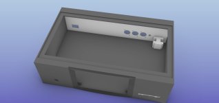
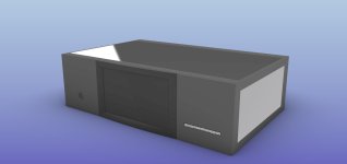
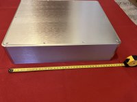
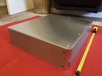
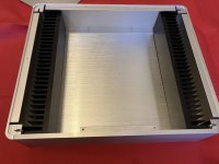
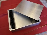
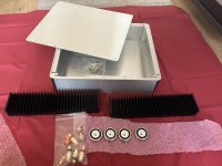
Beautiful case with rounded corners, this one here ENCLOSURE
W x 380mm H x 89mm D x 320mm
This has blank rear panel with no cut out as I wanted to use Power-con connectors.
Included are two 300mm x 70mm x 50mm heatsinks which fit inside the case perfectly, also 4 x 40mm feet, 2 x sets of Neutrik RCAs and Gold plated speaker binding posts.
This all weighs a few KG so would better for a UK member as postage is not cheap. Probably cost around £10 to send in UK.
Hi, I tried to repair the year-long issue with my father's JVC RC-Q50 boombox (FM radio, CD, cassette). It has a loose contact inside, the D-type power plug had to be in a specific angle, otherwise the boombox wouldn't turn on / shut itself off, back to standby. I used to bend the plug up by stacking cassette cases next to the boombox, but it was annoying since the slightest bump would cut the power. I found nothing obviously wrong with the power socket after I got the PCB with it out of the boombox. I de-soldered the power socket, it's part number is HSC1466, made by HOSIDEN, I disassembled the part itself and then the mishap happened. I heard two small pieces hitting the tiled floor, I looked everywhere but I only rediscovered the mechanical switch / lever. At first I wasn't even sure how that lever had to be put back inside the power socket. How I re-installed it at the end looks similar to the photo of the part inside the data sheet.
The lever between the two contacts for the D-type power plug will be pushed down by the power cable. The pins look a bit weird, I assumed that the contact would be better if I would bend them apart a bit, maybe that was the whole fault after all.
The lever in it's upright position, after I separated the two halves of the power socket.
When the lever is pushed down by the power cable, the three pins will be bend down.
The solder points of the three pins from before, back view of the power socket.
Screenshot from the PDF file of the part's data sheet / schematic which I found on www.datasheet.hk
After I found out how to correctly install the lever, I soldered the AC socket back in and tried it. I got no power at all. The lever / switch energizes the standby power circuit as far as I understand, since I am missing a part the circuit wouldn't be energized anymore.
Unfortunately I don't understand what should happen to the three contacts, I think they should be connected somehow as soon as the lever is pushed down by the power cord. Can someone tell me by looking at the schematic? I also cannot order a direct replacement of the part, it seems that it is nowhere available anymore, I remember that my father had this particular boombox since the early 90s tho. It would be nice to be able to repair it.
Thank you in advance.
Have focal es 165k speakers which came with 2 crossovers and memphis 400.4. Want to run all four on separate channels. Question is how do I wire. If I use 2 crossovers for the tweeters channels 1 and 2 where do I put the other four wires +, - for channels 3 and 4?
Wonder which factory manufactured this tube for Zaerix. It has a transparent disc with a strange pattern on the upper mica and is marked E74 on the glass. Four seams on top. The inner structure is askew, sloppily mounted or the result of bad handling. Doesn't sound bad, piqued my curiosity.
I have a bunch of drivers lying around but unsure what to do with them. I've got the itch to build and try something but I'd like to try something different. I've kinda gotten a bit bored of all my speakers and none of them really wow me anymore like they used to. So far I've made some Amiga's, two way waveguided monitor, big atc like three way, and econowave. I've got 3 way dsp for whatever I end up making.
newb question:
I'm thinking of "upgrading" a 10,000uf wall switching power supply by adding this in-line with the amplifier https://www.aliexpress.us/item/3256805990621738.html
my questions is mostly to see if it'll be compatible
I would like to do some mods on a Parasound HCA3500, any suggestions would be appreciated. I have read that upgrading the main feedback resistors and checking the polarity is a good place to start, the amp sounds good but can be a bit etchy on the top end. Where might I find schematics for the amp?
Thinking about using a Tentlabs negative bias module in combination with Rod Coleman's Filament Supply, to fixed-bias and dc-power the filaments of a DHT.
The Tentlabs module would provide the -85V to bias the grid, while Rod Coleman's module would supply the 5v for the filaments (see schematic below).
I am thinking about how I could make the 2 work together..
Hi! New to diy audio, hoping to learn as much as possible. I think Ill start with a dac build. If anybody has any recommendations on where to begin or good beginners resources, that would be much appreciated!
Any ideas on how to make this basement room work? One side is a solid wall and the other is open. It is currently just drywall. The room is intended as a social space for my kids to bring friends to, and for watching movies as a family on a projector we just bought (Benq gp500. My god the image quality is great!). There will be a thick carpet, and a large squishy L-sofa. I can probably manage some things on the walls to deal with reflections but it wont be extensive. As much as I love audio, the family function is more important to me so I just need to figure out how to manage the compromise.
Now that i have a house again, I'm can resume building speakers, and I can do pretty much anything. I have some conventional box speakers I want to get finished but I've wanted to do an OB along the lines of linkwitz for a long time and I hope that will be soon.
I'm under the impression that OB interacts less with the room but I wonder if this is beyond the scope of what it can improve on. Should I look at this path or constant directivity or some other format, or should I accept that this a fools errand and make do.
I'll eventually get around to all sorts of builds but It would be best to get something working well in this room first to keep everyone happy. Would love to hear some thoughts.
I have an Aco Pacific 70121/2" measurement microphone which I purchased with mellisa back in 1995 is basically flat from 3HZ to 40KHZ. I plan to use it with REW software. Rew needs a Mic. calibration data to be installed. The cal data consists of frequency, amplitude and phase angle. I only have the Mic frq. response curve, no phase response. I need to buy a usb audio interface.
Question 1. How do I get this data into REW?
Question 2. The software called Vituixcad has a spl trace tool that can convert the frq. response graph into a .txt file. Windows 10 or google chrome won't let me install it. For security reasons.
Question 3. How do I convert Mic. sensitivity from dB ref. 1V/Pa into db spl? 7012 sensitivity is -36 dB.
Have not used the 7012 in 2 decades. Not willing to have it cal'd for $135. and not willing to buy a Chinese usb mic.
Your help will be greatly appreciated. Mellisa is a dos based program. I still have the pc but it won't boot up due to a dead bios battery. no longer have the serial mouse or the din plug keyboard or the crt monitor that I once had.
As per a new thread posted today, looking for the best alternative for a very modern RV remodel and considering full range. I prefer OB but not sure it will work so a folded horn might be the way to go but if going to build something a snail shape enclosure would be a bit more fun than a regular box shape horn. My wife, incredibly tolerant, loves snail shaped speakers, she loves a great system far more of course, why not satisfy all our needs and wants at the same time!
I want to stick with my 10 watt tube amp(off grid eventually so will likely go D class then though hard to give up tubes!)
In the middle of a complete rebuild of our RV, everything one could imagine I am doing it so any links to a DIY plan for a good full range snail would be greatly appreciated!
This weekend I had a chance to listen to a nice 2x15" open baffle, that had a large curved front horn and a conical extension on the back. It sounded great and looked very cool. Therefore I would like to put together a test baffle inspired by it.
It would be really easy to build. What I do not like on a H frame are the parallel walls, here, only the top/bottom (not shown) would be parallel.
My question is, would this work? Would the baffle width be counted including both sides of the wings or would the bass frequencies ignore the inner triangle and just bend to the back?
All,
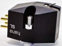
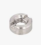
I don't understand how to tighten slotted nuts on cartridge screws (Hana SL cartridge). They are slotted type and screws stick out way beyond the nut surface. So no way to use flat screwdriver. Are there any special tools that exists for this ?
Please advice.
I have a push pull 813 amp with 1.3kva DC on the plates, 700VDC on G2.
I went from using a lead acid AGM 12 Volt battery for the filament supply (which sounded fantastic) , to a bridge rectifier ->68,000uf cap -> filaments - the noise (hum) was horrible.
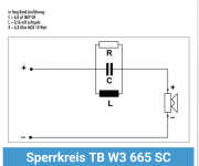
Hi. I'd like help understanding the center frequency of an existing parallel notch filter.
I'm just finishing some small full-range speakers, using the Tang Band W3-665sc I scavenged from some Logitech media speakers, Googling the driver model # when I saw the following Parallel notch filter posted by a German DIYer.
I tried to translate the caption, and it said the filter was to compensate for a driver basket resonance in the W3-665sc.
I am curious as to what frequency this is reputed to be.
I tried to reverse-engineer using the notch filter calculators online, but got conflicting results.
Can someone please tell me what the center frequency of this filter is? Thanks 🙏
and Happy New Year!
I'm trying to build a volume controller for a line level signal using the PT2258, which is a dedicated 6-channel volume controller IC. This is the reference circuit from the datasheet:
I built this circuit on a breadboard, and while it's functional there is a weird distortion of the signal. Here's a screenshot of what a sinewave (~300Hz) looks like coming in (yellow) and going out (blue), with the attenuation set to 0 dB:
Note that both signals are DC coupled, so it's clear the outgoing signal gets a DC offset from the PT2258. It also looks like the outgoing signal gets clipped at the bottom somehow.
In any case, I don't understand what I'm doing wrong here. I've rechecked the circuit I built several times and checked all the connections are good. So if anyone has any ideas what's going on here I'd love to hear about it.
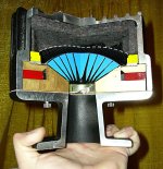
His results seemed to indicate that adding an extension increased the bandwidth of the overall tweeter/waveguide combo, while not screwing up the high frequencies too much, and keeping the polars about the same as a waveguide that doesn't have a deep throat.
The net effect is quite a bit like using one of those old timey compression drivers from the 70s or 80s, the ones that featured a 'stub' in the compression driver which was as long as 3-8cm. Basically, older compression drivers were quite a bit deeper with an exit angle that was quite a bit narrower than what we're accustomed to today.
So I wanted to bust out ATH and ABEC to see how things behave.
Does anybody know of a freeware (or pay) program that will generate Excellon .DRL files from Gerbers? My CircuitMaker2000 is finally giving up the ghost and refuses to do the job - the .DRL files is coming out with no drill hole sizes. I’m in the process of moving across to kiCAD 6, but it’s a steep learning curve and I don’t want to have to redesign the board as a first project at this stage.
Anybody has a BOM from Mouser or Digikey for the ESP P101 amplifier project that they could share? I have Rod's boards and parts list but feeling kinda lazy to go and do part picking. 🙂
Hi hi,
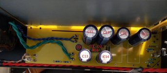
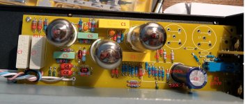
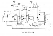
I am currently in the process of modding a Douk clone EAR 834P. Not reinventing the wheel here, mostly just upgrades of coupling caps and whatnot .. Thorsten Loeschs Mod guide is well known and I am mostly keeping to it. Most components were easy to identify on the board, but some are really strange. Maybe somebody with experience with the unit can help me.
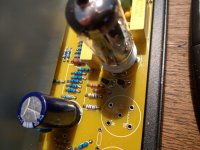
I have labelled a photo I am using for reference to the markings of the original schematic. I'm having trouble identifying the anode resistors of V1. They are supposed to be 330k, but I don't see them (maybe the two close to C8?..). I don't know where the 12 little 36k Resistors come in .. guessing they are somehow drawn together to substitute for a bigger resistor, but I don't yet know what and why. There is a single stray 68k Resistor close to V1 I can't place... And the strangest thing are two .. well I think semiconductors / transistors close to V1 labelled Q1 and Q2 (see last picture). What would they be doing there?...
Thanks a million.
I have a Smart TA-242 amplifier
DH19c boards I believe they are the same boards used on the DH 500 but with a lower power supply.
One channel is not working, no fuses are blown I believe the output gets are open. Need to be replaced.
strong amplifier!!!!
I'm moving I can't take it with me and I have no time for repairs. I don't want to throw it out.
Make me an offer. drdanrss@gmail.com
Due to the high cost of customs clearance in my country if I buy from diystore I am looking
Ιf anyone from Europe has the parts of the title and wants to sell them please contact me
I was surprised to find that my Scandinavian Audio Lab 08C08 drivers don't seem to like a very good solid state amplifier. I first tried them some time back in a biamped, open baffle setup driven (directly) by a vintage EL 84 amp, and they were quite nice. In the interim I moved on to try other speakers - vintage Tannoys. I eventually built my M2 clone. That amplifier is wonderful with Tannoys and a leap forward in general from anything I'd had to that point. I recently switched the SALs back in and... I was puzzled and disappointed. Rhiannon Giddens voice became really nasty on one album I was familiar with, for example. As a sanity check, I listened to the same song on some modest two ways in a second system, and there were absolutely no issues. I switched back in my old tube amps and the results, while less holographic than with the M2, were a lot more listenable.
I came across Nelson Pass's article on amp matching and learned that this is old hat - it's common to use tube amps with full range drivers due to synergies that I don't entirely understand.
Just wondering what sort of luck have people had with transistor amps and full range drivers.
has somebody a recommendation of a good DAC that is available in a eval board style PCB at Aliexpress?
I do have some other eval boards of a USB to I2S Bridge, CRS Bluetooth Chipset or ADAU1452.
Now I'm looking for a suitable DAC to build a quick tech-demo before putting everything into a custom DSP board.
My ADC and the USB Bridge are working at 192 kHz, 24 Bit. So this shoud be the minimum for the DAC.
in total I need 3 Channels for the Output. Speaker Left and Right and Subwoofer.
Ideal would be a 4th channel that I can use as an inverted signal since the Sub Amp is working on a differential input signal.
Highend chipsets like the ES9038q2m, ES9038pro or AK4493 seem to be state of the art, but I'm not sure how much hassle it is to get them running. Do I need additional commands from an external µController to configure them? So an ideal DAC for my purpose would be running out of the box or with some simple hardware pull-up / pull-downs.