The digital tape counter is designed for installation in reel-to-reel tape recorders. Many tape recorders have mechanical counters that are best replaced with electronic ones.

Counter features:
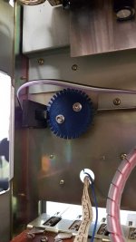
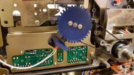
Tape move sensor
The transport of the tape recorder must have a rotating roller that is constantly in contact with the tape. The roller diameter can be from 30 to 60 mm, but you can add another range of diameters to the source code of the program. Reflective optocouplers are used as roller rotation sensors. Small size optocouplers are well suited, for example, CNB1302, ON2170, KTIR0711S, KTIR0811S, KTIR0821DS, ITR8307, TPR-105F, QRE1113. An chopper is installed on the roller, which should have 5 blades. Another number of blades is possible, but this number must be entered in the source code of the program. Two optocouplers are used, which allows you to determine the direction of rotation. Optocouplers are installed at an angle equal to half the angular size of one blade. As a result, signals shifted by 90 degrees are generated at the output of the optocouplers (quadrature signals).

Pulse shaper
The optocoupler pulse shaper circuit is taken from a Studer A820 tape recorder. The optocoupler signal is first amplified by a common-base transistor, then fed to a comparator (Counter_rev6_sch.pdf). The goal is to reduce the voltage swing at the output of the photodetector in order to speed up the recharge of parasitic capacitances. Such a scheme improves the shape of the pulses at a high repetition rate, which is observed in the rewind mode. To estimate the required frequency range, it is necessary to calculate the maximum speed of rotation of the roller. When rewinding, the tape speed can reach 10 m/s. With a roller diameter of about 40 mm, its rotational speed will be about 80 revolutions per second (4800 rpm). Considering the number of chopper blades, the maximum signal frequency from the output of each optocoupler will be about 400 Hz.
Quadrature decoder
In the simplest case, you can count the blades that pass over the sensors. This will be a 1X quadrature decoder. When one blade of the chopper passes over the sensors, 4 states of the output signals of the sensors are changed. It is advisable to use all these states to increase the accuracy of the sensor. This will be a 4X quadrature decoder. To implement such a decoder, the ability of microcontrollers to generate interrupts on any change in the state of port pins is suitable. This feature is available in the ATmega48/88/168/328 line of AVR microcontrollers. Decoding can be implemented in an interrupt. The easiest way to calculate the direction is by analyzing the previous state of one of the signals.

An important feature - the count +1 and -1 must occur at the same point. Otherwise, roller jitter near the switch point will cause an infinite increment or decrement. The text of the 4X quadrature decoder is below:
Optical sensors do not have a bounce, which happens in mechanical contacts. They can vibrate for a while, closing and opening. Optical sensors also have certain anomalies, but their nature is different. Near the switching point, the light flux changes smoothly, so the output is a signal with a fairly low slew rate. To form a digital signal with short edges, a certain threshold element is required. Any analog signal has noise and interference. Interference can have a variety of causes, ranging from electrical pickups and supply voltage ripples, ending with external illumination of variable intensity and mechanical vibration of the chopper, leading to modulation of the light flux. When the output voltage of the photodetector overcomes the threshold value, due to signal fluctuations at the output of the threshold element, a whole series of switching can occur, which will lead to an erroneous count. To prevent this from happening, the threshold element must have hysteresis. The logic inputs of the microcontroller also have hysteresis, but its value is small. It is better to use an external threshold element, for which the hysteresis value can be set arbitrarily. The dual comparator LM393 is well suited for this purpose.
Software processing
Each change in the state of the optical sensors triggers an interrupt. There will be 20 events per revolution of an chopper with 5 blades. In the interrupt handler, these events are counted in a small 8-bit counter. Periodically, the main program polls this counter and adds the count to the large 32-bit Events counter.
Based on the Events variable, the metrage value is calculated:
Metrage = Events * Diameter * PI / EV_PER_REV
Calculations are carried out in integer mathematics. To prevent error, the Metrage value is calculated in micrometers. The roller Diameter value is not a constant, but is calculated during the calibration process.
Based on the Metrage variable, the real time value for the selected tape speed is calculated:
Time = Metrage / Speed
Tape speed 9/19 or 19/38 is selected using an external 9/19 logic signal.
Timer1 based meter is used to calculate actual tape speed. The meter uses a capture interrupt - one of the optical sensor signal is applied to the ICP pin. When the meter starts, the software timer starts with the interval M_PRE_TM. If during this time no pulse comes from the sensor output, the speed is considered zero. The minimum measurable speed with these constant values is approximately 5 cm/s. When a pulse arrives from the optical sensor, the timer value is captured into the CapBeg variable, the measuring interval M_RUN_TM is started, and the counting of pulses begins. When the interval ends, the pulses are counted up to an integer number of roller revolutions (otherwise the mechanical inaccuracy of the chopper will lead to a measurement error). Time M_FIN_TM is allocated for the completion of the calculation. If during this time the required number of pulses does not arrive, the speed is considered zero. Based on the last pulse, the counter value is captured into the CapEnd variable and the duration of one roller revolution is calculated:
TurnTime = T_timer * (CapEnd - CapBeg) / Turns
Then, based on this duration and the diameter of the roller, the tape speed is calculated:
Speed = Diameter * PI / TurnTime
The roller diameter calibration procedure uses speed meter data. In order not to include the old roller diameter (which may have a large error) in the calculations, the measured speed value is not used. Instead, the duration of one roller revolution is used. To improve the accuracy of the calibration, the measurement is carried out CAL_CYCLES times, and the total time TimeSum is calculated. Then the diameter of the roller is calculated:
D = (TimeSum * SPEED_19) / (PI * CAL_CYCLES / T_timer)
The duration of the calibration is approximately 14 seconds, the measurement is carried out 10 times, each of them lasts 2 revolutions of the roller. If the calculated value of the roller diameter is not within the range of 30 to 70 mm, then a calibration error occurs. After calibration, the roller diameter is displayed with micron accuracy.
An unexpected problem
Overflow handling caused unexpected difficulties. The counter supports several different tape speeds, real time readings at each speed will be different. It also supports the display of metrage. The information capacity of the display in metrage mode is ±9999.99 meters, and in real time mode it is ±9 hours, 59 minutes, 59.9 seconds (±35999.9 seconds). At a speed of 38.1 cm/s this corresponds to a metrage of approximately ±13716 m, at a speed of 19.05 cm/s it is ±6858 m, at a speed of 9.525 cm/s it is ±3429 m. Obviously, when switching speed or switching metrage-time, when switching back, the value should return to the previous one. This means that the counter overflow must occur at the same point for all modes. But how can this be achieved?
At first I decided to limit the metrage range to ±2999.9 m, which is sufficient for any size reels with any tape thickness. But then the real time range was at a speed of 9.525 cm / s ± 8 hours, 44 minutes, 56 seconds (± 31496 seconds), at a speed of 19.05 cm / s ± 4 hours, 22 minutes, 28 seconds (± 15748 seconds), at a speed 38.1 cm/s ±2 hours, 11 minutes, 14 seconds (±7874 seconds). When indicating the time, the counter began to overflow at these rather unexpected points, and at different speeds at different ones. It looked a little eccentric.
Since the time indication mode is the main one, I decided to make the overflow point for this mode a round number. For different speeds, this point will be ±8.00.00.0, ±4.00.00.0, ±2.00.00.0. In the metrage measurement mode, the number, on the contrary, became ugly ± 2743.19.
On overflow, the maximum positive number should turn into the maximum negative number. Here, too, there were all sorts of miracles associated with rounding numbers. I even had to write a counter model on a PC in order to debug all situations related to its overflow.

How the tough guys solve this problem, I could not find out. With the accumulation of experience, instead of facilitating design, the understanding came that making any, even a simple thing, is very difficult.
Counter features:
- Real time display: hours.minutes.seconds (selectable tenths of a second)
- Tape length indication (selectable in decimeters or centimeters)
- Indication of actual tape speed (selectable in hundredths of cm/s or thousandths of cm/s)
- Roller diameter calibration for precise measurements (from 30 to 70 mm)
- Three speeds supported (9, 19, 38 or others)
- Two independent counters (for example, total time and lap time)
- Automatic saving of all values in EEPROM when power is turned off
- LED display 6 or 7 digits (selectable)
- Menu controlled via button or encoder (selectable)
- Port for the implementation of the locator (no software support yet)
Tape move sensor
The transport of the tape recorder must have a rotating roller that is constantly in contact with the tape. The roller diameter can be from 30 to 60 mm, but you can add another range of diameters to the source code of the program. Reflective optocouplers are used as roller rotation sensors. Small size optocouplers are well suited, for example, CNB1302, ON2170, KTIR0711S, KTIR0811S, KTIR0821DS, ITR8307, TPR-105F, QRE1113. An chopper is installed on the roller, which should have 5 blades. Another number of blades is possible, but this number must be entered in the source code of the program. Two optocouplers are used, which allows you to determine the direction of rotation. Optocouplers are installed at an angle equal to half the angular size of one blade. As a result, signals shifted by 90 degrees are generated at the output of the optocouplers (quadrature signals).
Pulse shaper
The optocoupler pulse shaper circuit is taken from a Studer A820 tape recorder. The optocoupler signal is first amplified by a common-base transistor, then fed to a comparator (Counter_rev6_sch.pdf). The goal is to reduce the voltage swing at the output of the photodetector in order to speed up the recharge of parasitic capacitances. Such a scheme improves the shape of the pulses at a high repetition rate, which is observed in the rewind mode. To estimate the required frequency range, it is necessary to calculate the maximum speed of rotation of the roller. When rewinding, the tape speed can reach 10 m/s. With a roller diameter of about 40 mm, its rotational speed will be about 80 revolutions per second (4800 rpm). Considering the number of chopper blades, the maximum signal frequency from the output of each optocoupler will be about 400 Hz.
Quadrature decoder
In the simplest case, you can count the blades that pass over the sensors. This will be a 1X quadrature decoder. When one blade of the chopper passes over the sensors, 4 states of the output signals of the sensors are changed. It is advisable to use all these states to increase the accuracy of the sensor. This will be a 4X quadrature decoder. To implement such a decoder, the ability of microcontrollers to generate interrupts on any change in the state of port pins is suitable. This feature is available in the ATmega48/88/168/328 line of AVR microcontrollers. Decoding can be implemented in an interrupt. The easiest way to calculate the direction is by analyzing the previous state of one of the signals.
An important feature - the count +1 and -1 must occur at the same point. Otherwise, roller jitter near the switch point will cause an infinite increment or decrement. The text of the 4X quadrature decoder is below:
Code:
#pragma vector = PCINT0_vect
__interrupt void Opto_Handler(void)
{
  static bool preF1 = 0;
  bool nowF1 = TCount::Pin_F1;
  bool nowF2 = TCount::Pin_F2;
  (preF1 == nowF2)? TCount::Count-- : TCount::Count++;
  preF1 = nowF1;
}
Optical sensors do not have a bounce, which happens in mechanical contacts. They can vibrate for a while, closing and opening. Optical sensors also have certain anomalies, but their nature is different. Near the switching point, the light flux changes smoothly, so the output is a signal with a fairly low slew rate. To form a digital signal with short edges, a certain threshold element is required. Any analog signal has noise and interference. Interference can have a variety of causes, ranging from electrical pickups and supply voltage ripples, ending with external illumination of variable intensity and mechanical vibration of the chopper, leading to modulation of the light flux. When the output voltage of the photodetector overcomes the threshold value, due to signal fluctuations at the output of the threshold element, a whole series of switching can occur, which will lead to an erroneous count. To prevent this from happening, the threshold element must have hysteresis. The logic inputs of the microcontroller also have hysteresis, but its value is small. It is better to use an external threshold element, for which the hysteresis value can be set arbitrarily. The dual comparator LM393 is well suited for this purpose.
Software processing
Each change in the state of the optical sensors triggers an interrupt. There will be 20 events per revolution of an chopper with 5 blades. In the interrupt handler, these events are counted in a small 8-bit counter. Periodically, the main program polls this counter and adds the count to the large 32-bit Events counter.
Based on the Events variable, the metrage value is calculated:
Metrage = Events * Diameter * PI / EV_PER_REV
Calculations are carried out in integer mathematics. To prevent error, the Metrage value is calculated in micrometers. The roller Diameter value is not a constant, but is calculated during the calibration process.
Based on the Metrage variable, the real time value for the selected tape speed is calculated:
Time = Metrage / Speed
Tape speed 9/19 or 19/38 is selected using an external 9/19 logic signal.
Timer1 based meter is used to calculate actual tape speed. The meter uses a capture interrupt - one of the optical sensor signal is applied to the ICP pin. When the meter starts, the software timer starts with the interval M_PRE_TM. If during this time no pulse comes from the sensor output, the speed is considered zero. The minimum measurable speed with these constant values is approximately 5 cm/s. When a pulse arrives from the optical sensor, the timer value is captured into the CapBeg variable, the measuring interval M_RUN_TM is started, and the counting of pulses begins. When the interval ends, the pulses are counted up to an integer number of roller revolutions (otherwise the mechanical inaccuracy of the chopper will lead to a measurement error). Time M_FIN_TM is allocated for the completion of the calculation. If during this time the required number of pulses does not arrive, the speed is considered zero. Based on the last pulse, the counter value is captured into the CapEnd variable and the duration of one roller revolution is calculated:
TurnTime = T_timer * (CapEnd - CapBeg) / Turns
Then, based on this duration and the diameter of the roller, the tape speed is calculated:
Speed = Diameter * PI / TurnTime
The roller diameter calibration procedure uses speed meter data. In order not to include the old roller diameter (which may have a large error) in the calculations, the measured speed value is not used. Instead, the duration of one roller revolution is used. To improve the accuracy of the calibration, the measurement is carried out CAL_CYCLES times, and the total time TimeSum is calculated. Then the diameter of the roller is calculated:
D = (TimeSum * SPEED_19) / (PI * CAL_CYCLES / T_timer)
The duration of the calibration is approximately 14 seconds, the measurement is carried out 10 times, each of them lasts 2 revolutions of the roller. If the calculated value of the roller diameter is not within the range of 30 to 70 mm, then a calibration error occurs. After calibration, the roller diameter is displayed with micron accuracy.
An unexpected problem
Overflow handling caused unexpected difficulties. The counter supports several different tape speeds, real time readings at each speed will be different. It also supports the display of metrage. The information capacity of the display in metrage mode is ±9999.99 meters, and in real time mode it is ±9 hours, 59 minutes, 59.9 seconds (±35999.9 seconds). At a speed of 38.1 cm/s this corresponds to a metrage of approximately ±13716 m, at a speed of 19.05 cm/s it is ±6858 m, at a speed of 9.525 cm/s it is ±3429 m. Obviously, when switching speed or switching metrage-time, when switching back, the value should return to the previous one. This means that the counter overflow must occur at the same point for all modes. But how can this be achieved?
At first I decided to limit the metrage range to ±2999.9 m, which is sufficient for any size reels with any tape thickness. But then the real time range was at a speed of 9.525 cm / s ± 8 hours, 44 minutes, 56 seconds (± 31496 seconds), at a speed of 19.05 cm / s ± 4 hours, 22 minutes, 28 seconds (± 15748 seconds), at a speed 38.1 cm/s ±2 hours, 11 minutes, 14 seconds (±7874 seconds). When indicating the time, the counter began to overflow at these rather unexpected points, and at different speeds at different ones. It looked a little eccentric.
Since the time indication mode is the main one, I decided to make the overflow point for this mode a round number. For different speeds, this point will be ±8.00.00.0, ±4.00.00.0, ±2.00.00.0. In the metrage measurement mode, the number, on the contrary, became ugly ± 2743.19.
On overflow, the maximum positive number should turn into the maximum negative number. Here, too, there were all sorts of miracles associated with rounding numbers. I even had to write a counter model on a PC in order to debug all situations related to its overflow.
How the tough guys solve this problem, I could not find out. With the accumulation of experience, instead of facilitating design, the understanding came that making any, even a simple thing, is very difficult.
Last edited:

Indication
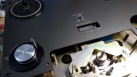
The tape counter is designed for installation in a reel-to-reel tape recorder of the 80s. Therefore, it is desirable that it does not violate the general style of the device and be made on those display elements that were common at that time. As a result, Kingbright SA39-11SRWA LED indicators with a digit height of 0.39 inches were selected. Other indicators can be used, but this will require reworking the printed circuit board. You can use 6 or 7 indicators.
Most often, when indicators are connected to the microcontroller, dynamic indication is used. In this case, the consumed current pulses. Interference with the scanning frequency (and it usually falls in the audio frequency range) can pass into the audio path, which is undesirable. Therefore, it is better not to use dynamic indication. To implement a static indication, you can use a chain of shift registers. Each digit of the indicator will then be connected to a separate register, which can be loaded via a serial interface. At the same time, the number of ICs in the circuit increases, and resistors are needed for each segment of all indicators. Resistors can be eliminated by using special LED driver chips. These are also shift registers, but their outputs are designed to provide constant current. An example is the MBI5170 chip. But the price and availability of such ICs is not very good. As a result, the most affordable solution is to use 6 or 7 shift registers like 74HC595 with 0603 resistors on each of their outputs.
Saving readings
A conventional mechanical counter retains its readings when the tape recorder is turned off. It is desirable that the electronic counter behaves in the same way. Saving is best done at the moment when the supply voltage starts to drop. The microcontroller consumes very little power. You can store the necessary charge in a small capacitor. At the same time, it must be ensured that extraneous consumers are disconnected when the power is turned off. The capacitor must be powered through a diode so that it is not discharged by other consumers along the +5 V circuit. Using a Schottky diode will cause a decrease in the processor supply voltage by about 0.5 V, i.e. instead of 5 V there will be 4.5 V. This will not cause any problems. You also need to add a circuit for detecting a drop in the main power supply. For these purposes, you can use the built-in comparator of the microcontroller and the built-in reference source. When the comparator is triggered, an interrupt will occur, the processor quickly turns off all unnecessary consumers and stores the current count value in EEPROM. When power is restored, the processor starts in the usual way, reads the stored value from the EEPROM and is then ready to continue counting.
Special handling requires a situation where the power has decreased for a short time, and has not disappeared completely (brown out, not black out). The comparator will see a voltage drop, but the processor will continue to run. In such a case, an automatic return to normal operation is provided. If normal power is restored after the data is stored in the EEPROM, the microcontroller ports will be set up again and counting will continue with minimal loss.
The capacitor must be chosen so that the discharge time to 2.7 V is about 50...100 ms. For this, a capacitance of 220 uF is sufficient. This is a small tantalum capacitor in a "D" case (7.3 x 4.3 x 2.9 mm).
Control
The counter is controlled with a single button (firmware version 1.xx) or with an encoder with a button (version 2.00 and higher). It is recommended to use an encoder as it is more convenient. Further there will be a description of only the control of the encoder.
When the power is turned on, all indicator segments, including dots, light up on the counter. This is done for testing purposes, the faulty segment will be immediately visible. After 1 sec, the short name of the mode is displayed (for example, brief name "rtc-1" - real time counter 1), then after 1 sec, the count value is displayed. If you keep the encoder button pressed when turning on the power, the firmware version number (eg "2.02") is displayed instead of testing the display.

By turning the encoder knob, you can select the display modes:
"rtc-1" - real time counter 1
"LEn-1" - tape length 1
"rtc-2" - real time counter 2
"LEn-2" - tape length 2
"SPEEd" - tape speed

The count values can be reset by briefly pressing the encoder button. "rtc-1" and "LEn-1" are different representations of the same count value and are therefore reset at the same time. The same is true for the "rtc-2" and "LEn-2" pair. "rtc-1" can be reset at the beginning of the reel, this will be the absolute play time. "rtc-2" can be used to measure the duration of fragments and reset at their beginning.
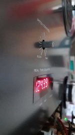
Real time is displayed in hours, minutes, seconds and tenths of a second (if enabled in the menu). Points are used as separators. To visually distinguish "rtc-2" and "LEn-2", dots are displayed at the end of them.
The metrage is displayed in meters and decimeters (or centimeters, if allowed in the menu). A dot is used as a separator.
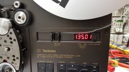
The tape speed is displayed in centimeters per second with a resolution of 0.01 cm/s or 0.001 cm/s (as selected in the menu), the dot is displayed after the centimeter value.
Time and metrage are counted up and down (with a minus sign). This is convenient for a reverse tape deck, since when the tape moves in the reverse direction, real time (with a minus sign) can be observed, and not a countdown.
The current counter display mode is stored in EEPROM and restored when the power is turned on. The values of all counters and roller diameter are also stored in EEPROM.
Resetting is not possible for speed readings, so pressing the encoder button will display the roller diameter in mm (e.g. "d 37.900"). If you now press and hold the encoder button for 4 seconds, the roller diameter calibration mode will start.

Calibration is only possible at 19.05 cm/s. Before calibration, it is necessary to adjust the speed of the tape recorder using a test tape. When calibration starts, "d CAL" flashes on the display. Calibration lasts about 14 seconds, at the end the display will show a new value for the roller diameter (eg "d 37.749"). If the calibration fails (for example, the tape did not move or its speed was very different from the nominal), the display will show "d Err". In this case, you can either repeat the calibration by long holding the button, or exit it by short pressing, while the new value will not be saved. If the encoder button is pressed during calibration, the process will be interrupted. If the button is held for 1 second, the default value of the roller diameter will be loaded. After calibration, the encoder button must be pressed to accept the new roller diameter value. Permissible calibration limits for the roller diameter are from 30 to 70 mm.
When you hold the encoder button for 1 second from any display mode, you enter the configuration menu. In this case, "SEtUP" appears on the display, and after 1 sec. the menu is displayed. The transition between menu items is done by turning the encoder, the choice of options for each item is made by a series of short presses. The menu has the following items:

1. "ESC" - by pressing the encoder you can exit the menu without saving.
2. Selection of a set of displayed values (you can turn off unnecessary ones):
"tLtLS" - displayed time 1 (rtc-1), metrage 1 (LEn-1), time 2 (rtc-2), metrage 2 (LEn-2), tape speed (SPEEd)
"tLtS" - displayed time 1, metrage 1, time 2, tape speed
"ttS" - displayed time 1, time 2, tape speed
"tS" - displayed time 1, tape speed
"t" - displayed time 1
3. Enable/disable tenths of a second:
"rtc" - display of tenths of a second is off
"rtcHI" - display of tenths of a second is on (rtc HI resolution)
4. Enable/disable centimeters:
"LEn" - metrage is displayed in decimeters
"LEnHI" - metrage is displayed in centimeters (length HI resolution)

5. Enable/disable thousandth cm/s:
"SPd" - speed is displayed to hundredths of cm/s
"SPdHI" - speed is displayed to thousandths of cm/s (speed HI resolution)
"SPdHL" - also to thousandths of cm/s, but the output is shifted to the left
6. Font selection for numbers 6, 7, 9:
"769" - simple font
"'769" - digit 7 has an additional segment F
"7bq" - digit 6 without segment A, digit 9 without segment D
"'7bq" - 7 with F, 6 without A, 9 without D
7. Selecting the logic of the speed switching signal:
"H19L9" - high level - 19, low level - 9
"H9L19" - high level - 9, low level - 19
"H38L19" - high level - 38, low level - 19
"H19L38" - high level - 19, low level - 38
8. "SEt" - by pressing the encoder, you can exit with saving to EEPROM.
9. "dEF" - by pressing the encoder you can return to the default settings.
The exit from the configuration menu is always carried out in the "rtc-1" menu, regardless of which menu you entered from. To save the changes, you must exit through the "SEt" item.
For the correct operation of the firmware on a board with a 6-digit display, you must disable the high resolution for time and metrage. For speed, you can select a high resolution with a shift to the left by one digit.
If the tape speed display is disabled, then it becomes impossible to enter the roller diameter calibration. To calibrate, you must temporarily turn on the display of the tape speed.
Counter design
The counter is assembled on a single printed circuit board, the shape of which is selected for a specific tape recorder.


There is also a more universal option when the meter has 3 boards: an optical sensor, a processor and an indication board.

Schematic note: the resistor values in the schematic are for KTIR0821DS optocouplers that have Darlington phototransistors. For optocouplers with a single phototransistors (for example, ITR8307), the resistor values R3 and R4 should be 100 k, R7 and R8 - 2.2 M. Perhaps these resistor values will have to be selected for a particular type of optocouplers.
The firmware is written in C++, I don’t attach the source code yet, the comments will have to be translated into English, this is a lot of work.
The tape counter is designed for installation in a reel-to-reel tape recorder of the 80s. Therefore, it is desirable that it does not violate the general style of the device and be made on those display elements that were common at that time. As a result, Kingbright SA39-11SRWA LED indicators with a digit height of 0.39 inches were selected. Other indicators can be used, but this will require reworking the printed circuit board. You can use 6 or 7 indicators.
Most often, when indicators are connected to the microcontroller, dynamic indication is used. In this case, the consumed current pulses. Interference with the scanning frequency (and it usually falls in the audio frequency range) can pass into the audio path, which is undesirable. Therefore, it is better not to use dynamic indication. To implement a static indication, you can use a chain of shift registers. Each digit of the indicator will then be connected to a separate register, which can be loaded via a serial interface. At the same time, the number of ICs in the circuit increases, and resistors are needed for each segment of all indicators. Resistors can be eliminated by using special LED driver chips. These are also shift registers, but their outputs are designed to provide constant current. An example is the MBI5170 chip. But the price and availability of such ICs is not very good. As a result, the most affordable solution is to use 6 or 7 shift registers like 74HC595 with 0603 resistors on each of their outputs.
Saving readings
A conventional mechanical counter retains its readings when the tape recorder is turned off. It is desirable that the electronic counter behaves in the same way. Saving is best done at the moment when the supply voltage starts to drop. The microcontroller consumes very little power. You can store the necessary charge in a small capacitor. At the same time, it must be ensured that extraneous consumers are disconnected when the power is turned off. The capacitor must be powered through a diode so that it is not discharged by other consumers along the +5 V circuit. Using a Schottky diode will cause a decrease in the processor supply voltage by about 0.5 V, i.e. instead of 5 V there will be 4.5 V. This will not cause any problems. You also need to add a circuit for detecting a drop in the main power supply. For these purposes, you can use the built-in comparator of the microcontroller and the built-in reference source. When the comparator is triggered, an interrupt will occur, the processor quickly turns off all unnecessary consumers and stores the current count value in EEPROM. When power is restored, the processor starts in the usual way, reads the stored value from the EEPROM and is then ready to continue counting.
Special handling requires a situation where the power has decreased for a short time, and has not disappeared completely (brown out, not black out). The comparator will see a voltage drop, but the processor will continue to run. In such a case, an automatic return to normal operation is provided. If normal power is restored after the data is stored in the EEPROM, the microcontroller ports will be set up again and counting will continue with minimal loss.
The capacitor must be chosen so that the discharge time to 2.7 V is about 50...100 ms. For this, a capacitance of 220 uF is sufficient. This is a small tantalum capacitor in a "D" case (7.3 x 4.3 x 2.9 mm).
Control
The counter is controlled with a single button (firmware version 1.xx) or with an encoder with a button (version 2.00 and higher). It is recommended to use an encoder as it is more convenient. Further there will be a description of only the control of the encoder.
When the power is turned on, all indicator segments, including dots, light up on the counter. This is done for testing purposes, the faulty segment will be immediately visible. After 1 sec, the short name of the mode is displayed (for example, brief name "rtc-1" - real time counter 1), then after 1 sec, the count value is displayed. If you keep the encoder button pressed when turning on the power, the firmware version number (eg "2.02") is displayed instead of testing the display.
By turning the encoder knob, you can select the display modes:
"rtc-1" - real time counter 1
"LEn-1" - tape length 1
"rtc-2" - real time counter 2
"LEn-2" - tape length 2
"SPEEd" - tape speed
The count values can be reset by briefly pressing the encoder button. "rtc-1" and "LEn-1" are different representations of the same count value and are therefore reset at the same time. The same is true for the "rtc-2" and "LEn-2" pair. "rtc-1" can be reset at the beginning of the reel, this will be the absolute play time. "rtc-2" can be used to measure the duration of fragments and reset at their beginning.
Real time is displayed in hours, minutes, seconds and tenths of a second (if enabled in the menu). Points are used as separators. To visually distinguish "rtc-2" and "LEn-2", dots are displayed at the end of them.
The metrage is displayed in meters and decimeters (or centimeters, if allowed in the menu). A dot is used as a separator.
The tape speed is displayed in centimeters per second with a resolution of 0.01 cm/s or 0.001 cm/s (as selected in the menu), the dot is displayed after the centimeter value.
Time and metrage are counted up and down (with a minus sign). This is convenient for a reverse tape deck, since when the tape moves in the reverse direction, real time (with a minus sign) can be observed, and not a countdown.
The current counter display mode is stored in EEPROM and restored when the power is turned on. The values of all counters and roller diameter are also stored in EEPROM.
Resetting is not possible for speed readings, so pressing the encoder button will display the roller diameter in mm (e.g. "d 37.900"). If you now press and hold the encoder button for 4 seconds, the roller diameter calibration mode will start.
Calibration is only possible at 19.05 cm/s. Before calibration, it is necessary to adjust the speed of the tape recorder using a test tape. When calibration starts, "d CAL" flashes on the display. Calibration lasts about 14 seconds, at the end the display will show a new value for the roller diameter (eg "d 37.749"). If the calibration fails (for example, the tape did not move or its speed was very different from the nominal), the display will show "d Err". In this case, you can either repeat the calibration by long holding the button, or exit it by short pressing, while the new value will not be saved. If the encoder button is pressed during calibration, the process will be interrupted. If the button is held for 1 second, the default value of the roller diameter will be loaded. After calibration, the encoder button must be pressed to accept the new roller diameter value. Permissible calibration limits for the roller diameter are from 30 to 70 mm.
When you hold the encoder button for 1 second from any display mode, you enter the configuration menu. In this case, "SEtUP" appears on the display, and after 1 sec. the menu is displayed. The transition between menu items is done by turning the encoder, the choice of options for each item is made by a series of short presses. The menu has the following items:
1. "ESC" - by pressing the encoder you can exit the menu without saving.
2. Selection of a set of displayed values (you can turn off unnecessary ones):
"tLtLS" - displayed time 1 (rtc-1), metrage 1 (LEn-1), time 2 (rtc-2), metrage 2 (LEn-2), tape speed (SPEEd)
"tLtS" - displayed time 1, metrage 1, time 2, tape speed
"ttS" - displayed time 1, time 2, tape speed
"tS" - displayed time 1, tape speed
"t" - displayed time 1
3. Enable/disable tenths of a second:
"rtc" - display of tenths of a second is off
"rtcHI" - display of tenths of a second is on (rtc HI resolution)
4. Enable/disable centimeters:
"LEn" - metrage is displayed in decimeters
"LEnHI" - metrage is displayed in centimeters (length HI resolution)
5. Enable/disable thousandth cm/s:
"SPd" - speed is displayed to hundredths of cm/s
"SPdHI" - speed is displayed to thousandths of cm/s (speed HI resolution)
"SPdHL" - also to thousandths of cm/s, but the output is shifted to the left
6. Font selection for numbers 6, 7, 9:
"769" - simple font
"'769" - digit 7 has an additional segment F
"7bq" - digit 6 without segment A, digit 9 without segment D
"'7bq" - 7 with F, 6 without A, 9 without D
7. Selecting the logic of the speed switching signal:
"H19L9" - high level - 19, low level - 9
"H9L19" - high level - 9, low level - 19
"H38L19" - high level - 38, low level - 19
"H19L38" - high level - 19, low level - 38
8. "SEt" - by pressing the encoder, you can exit with saving to EEPROM.
9. "dEF" - by pressing the encoder you can return to the default settings.
The exit from the configuration menu is always carried out in the "rtc-1" menu, regardless of which menu you entered from. To save the changes, you must exit through the "SEt" item.
For the correct operation of the firmware on a board with a 6-digit display, you must disable the high resolution for time and metrage. For speed, you can select a high resolution with a shift to the left by one digit.
If the tape speed display is disabled, then it becomes impossible to enter the roller diameter calibration. To calibrate, you must temporarily turn on the display of the tape speed.
Counter design
The counter is assembled on a single printed circuit board, the shape of which is selected for a specific tape recorder.
There is also a more universal option when the meter has 3 boards: an optical sensor, a processor and an indication board.
Schematic note: the resistor values in the schematic are for KTIR0821DS optocouplers that have Darlington phototransistors. For optocouplers with a single phototransistors (for example, ITR8307), the resistor values R3 and R4 should be 100 k, R7 and R8 - 2.2 M. Perhaps these resistor values will have to be selected for a particular type of optocouplers.
The firmware is written in C++, I don’t attach the source code yet, the comments will have to be translated into English, this is a lot of work.
Attachments
Last edited:
Hallo, sehr schöne Arbeit, Respekt!!
Etwas ähnliches habe ich vor Jahren gebaut. Hauptsächlich für Akai GX 6xx und für Technics 15xx.
Alles kann über die Nullstelltaste eingestellt werden. Abweichung bei 1100m ca. 1s. Akai Echtzeit-Geschwindigkeitsumschaltung und echte Echtzeitanzeige 9/19cm.
Bei der Technics auch. Dort wechseln Sie von 9/19/38cm mit sofortiger korrekter Anzeige. Ihre scheint für ACR oder Revox zu sein. Ich mag die Dezimalstelle nach der Sekunde sehr. Alles Gute
Attachments
-
 20190130_123553.jpg42.4 KB · Views: 153
 -
 20190214_085408.jpg58.8 KB · Views: 361
 -
 20200110_103820.jpg73.5 KB · Views: 195
 -
 20200206_143751.jpg51.5 KB · Views: 152
 -
 Akai-GX-635-Black_0088.jpg46.1 KB · Views: 329
 -
 20200216_094758.jpg23.6 KB · Views: 161
 -
 Akai-GX-635-Black_0110.jpg23.8 KB · Views: 296
 -
 Echtzeittest-mit-Stopuhr-ca.2sec-bei-2h30min.mp4_snapshot_00.jpg51.5 KB · Views: 167
Last edited:
 @Smithy G diyAudio is an English language forum. You must post in English or supply a translation. This is clearly stated in the forum rules.
Here is the English version of your post above. Please post in English, we will not provide further translations.
Hello, very nice work, respect!!
I built something similar years ago. Mainly for Akai GX 6xx and for Technics 15xx.
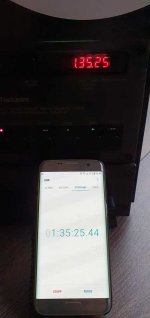
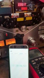
Everything can be set using the zero button. Deviation at 1100m approx. 1s. Akai real-time speed switching and true real-time display 9/19cm.
At the Technics too. There you change from 9/19/38cm with immediate correct display. Yours seems to be for ACR or Revox. I really like the decimal place after the second. All the best
Pano, thanks for the translation.
Smithy G, nice work too! My version is used for Revox and its clones. Tenths of a second can be turned off, because not everyone likes them, they flicker too much.
For Technics, it was probably possible to do without unnecessary mechanics if you use a reflective optocoupler and a strip with strokes.
Yes, that's the only drawback. The circuit is adapted from the Akai GX. I needed a rotational constant that always remained the same. That was the capstan shaft and both pulleys. Otherwise, a calculation would have had to take place on both engines. That was the easiest way.
Hi.Hallo, sehr schöne Arbeit, Respekt!!
Etwas ähnliches habe ich vor Jahren gebaut. Hauptsächlich für Akai GX 6xx und für Technics 15xx.
Alles kann über die Nullstelltaste eingestellt werden. Abweichung bei 1100m ca. 1s. Akai Echtzeit-Geschwindigkeitsumschaltung und echte Echtzeitanzeige 9/19cm.
Bei der Technics auch. Dort wechseln Sie von 9/19/38cm mit sofortiger korrekter Anzeige. Ihre scheint für ACR oder Revox zu sein. Ich mag die Dezimalstelle nach der Sekunde sehr. Alles Gute
I bought a AKAI 646 and I am very interested in installing a digital counter. I like very much your work and I am interested how can I buy one from you, or how can I obtain necessary info for making one like you do.
Best regards, Dorin.
I have downloaded all the files but I wonder which version of KICAD was used. I cannot open the design
from the .pro file with KICAD v6, nor can I open the Gerber files. I haven't found any BOM file either.
Is this more or less the same Tape Counter using an Arduino Nano published in the
https://old-fidelity-forum.de/thread-38940.html?
from the .pro file with KICAD v6, nor can I open the Gerber files. I haven't found any BOM file either.
Is this more or less the same Tape Counter using an Arduino Nano published in the
https://old-fidelity-forum.de/thread-38940.html?
This project is completely different from the project from the old-fidelity-forum.de.
The printed circuit board is designed in PCAD 2006. I attached files (gerbers are included) for the latest version 12.
The printed circuit board is designed in PCAD 2006. I attached files (gerbers are included) for the latest version 12.
Attachments
Last edited:
A detailed description of the counter can be found here (using Google Translate).Do you have cabling instruction for Revox A700/ B77 and programming? What do you need to program the counter, I mean download to the eeprom?
To track the velocity of the tape, capstan not used, but a guide roller. The tape is in contact and during fast rewinding. The rotation of the reel motors is not monitored.
I have managed to order all the components except the three connectors to the left and the button for the encoder. Can you please give me the references (male and female). Is the counter mechanically compatible with the A700?
Is there a version 12 for the "split in three" version and would it be possible to install in the B77?
Krikke944
Is there a version 12 for the "split in three" version and would it be possible to install in the B77?
Krikke944
- Home
- Source & Line
- Analogue Source
- Digital tape counter for R-R deck