Is this an ML 38?

Dear all,
a friend of mine bought a closed hifi shop in my town and, in the leftovers, he found this board which should belong to a Mark Levinson device, probably a preamp.
I see some similarities with the ML38(s) but I am definitely not sure. Is there anybody who can help me identifying it?
I would also be happy to understand if it can be reused in any way

Thank you in advance
Gaetano

Attachments

  • IMG_1926.png
    IMG_1926.png
    1.5 MB · Views: 192
  • IMG_1925.png
    IMG_1925.png
    1.5 MB · Views: 165
  • IMG_1924.png
    IMG_1924.png
    5.1 MB · Views: 161
  • IMG_1923.png
    IMG_1923.png
    5.6 MB · Views: 167

Isetta/FE85

I have Just discovered that the Fountek fe85 appears to have been discontinued which scuppers my plan to make an isetta for my kitchen. Does anyone know of a design using a alternative full range driver which could stand in for the fe85?
I am also open to other designs but the isetta seemed to be perfect with solid bass and not too large as it will be sitting in my bay window. I would really like to use the tangband sub for this as it appears to be universally liked for this application.

Clarion 4N25 Opto Coupler

I just had the experience of having my Clarion APX amp go silent after tending to some dirty switches.

After an extensive investigation; signal through crossover, power supplies, lifting pins, checking transistors, I rolled the dice and hacked in a jumper to the (U5) 6 pin, 4N25 opto-coupler, and it worked to allow the amp to function again(!?)

So while I am pleased that things appear to be better, I can only wonder what purpose that portion of the amp serves?

The design is very elegant and not being an esoteric type, I can imagine it’s there to protect something or serve a durability function. It was not on any of my various Clarion APX schematics I have.

Does anyone know what that part does?

Thanks.

HiFi phase splitter - "best" design option?

Happy New Year, one and all....

My project for a 6AS7 PP stereo amplifier is nearing a reality, however when considering various design options I have a dilemma: What type of circuit should I use as a phase splitter? I've read various pros and cons about several types and I must admit, I'm none the wiser....

The design parameters are:
  • I want to use a single 6N1P double triode to be phase splitter/driver for the PP 6AS7 power stage;
  • the design will use a single positive B+ supply of between 250v and 290vdc, so no negative supply available;
  • each triode in the 6AS7 will be Cathode biased using a 1k2 resistor and 100uF electrolytic, hopefully to achieve a little over 80mA plate current per triode;
  • some negative feedback would be ideal;
  • I understand that 6AS7 needs a wide voltage driver swing to get a useful power output (aim is for ~12w per channel);
  • the input pre-amp would be one side of a 6SL7;
  • the usage is for hi-fi so an option with low inherent distortion is required.

The overall design is 1-off 6SL7 plus 2-off 6N1P plus 2-off 6AS7. DC supply will be solid state rectified. This is for an existing chassis that I want to re-purpose using the valves stated.

Constructive comments sought from you wonderful people out there....

Help check RCRCRC and cap mult

Hello there!

I have two goals:

  • Get a capacitance multiplier for a chip amp (TDA7377 / STA540)
  • Learn how to make a PCB with Kicad

Other than any feedback you have I am wondering:

  • Maybe more than one output transistor is overkill but I'd like to keep at least two to have them run cool. Is it OK?
  • I have a small dual-40mh coil. Is it useful to make a low-pass before the BD139 base with it? BTW, I joined pins to make a single coil and measured 120mH. Wondering if that's useful.

This is the circuit I get and the simulation with a 8-ohm load. I didn't set the ESR of the capacitors. I cannot measure it right now.

1705170225573.png

1705170325568.png

Attachments

  • 1705170058236.png
    1705170058236.png
    75.4 KB · Views: 83

What amp board to use with a SMPS500R?

So back in 2016 I build myself an amplifier using an SMPS500R and a pair of L-15D-PRO (IRS2092) boards. While I'm not really dissatisfied with the amp in any way apart from maybe some hiss from the speakers when I have my ears a few decimeters from them, but I am still curious if I could upgrade it bit.

So the weak part is of course the amp boards themselves, so I was wondering what I could use instead of those boards with my SMPS500R? It's a 500w (650w peak) +-45V dual voltage power supply. Not sure exactly what the "dual voltage" actually means since I just bought the stuff after reading about it here and on some other places, but it have three outputs from the power supply to the boards, plus, minus and ground , and with my limited experience I've really never seen this apart from on this boards.
So my question is if it's possible to use this power supply with other boards like some of the modern TPA3255 boards, or am I limited to some obscure dual voltage boards?


Posting some images on my amp for attention as well 😉 Build the case out of an old computer case and some finer wooden boards. Still quite happy with the look and size of it, though the on/off switch in the front doesn't work (it physically doesn't switch as it should, not sure why) and the LED in the front doesn't actually light up (photoshop baby!) even though I've connected it to the aux on the power supply. Ah well, it does the job!

DSC00920.jpg

DSC00931.jpg

My new amps: Jack Elliano, Bud Purvin, Asnain Kolarkar

Hi all,

Thought that I would show off my new amps that I have been enjoying the past few days.

These amps are results of a collaboration between Asnain Kolarkar, my close friend , and the two famous gurus , who need no introduction.

Asnain is here in India and is an expert in transformer design and winding, and also very good at designing circuits.
He is based in India and runs a hobbyshop , Kolarkar Audio research, to cater to his interests. He has been in touch with both Jack and Bud since the last few years , and considering his knowledge and skill levels , they have authorised him to carry on with their work and designs.

So what do I have ?

1) 6AQ5 amp
Jointly designed by Bud and Asnain , this is a SE class A amp that is running the 6AQ5 power tubes in UL mode. Output is 3.25 WPC with frequency response 17Hz to 60K . No feedback has been employed, and distortion levels are vanishingly low. The driver is 6N2P , tube rectification can employ most of the octal rectifiers.

2) EL84 amp in A3 topology
SE in A3 topology is Jack Elliano's proprietary design. What I have is an EL84 amp in that configuration, punching out 10 wpc😱🤩


Both the amps are very musical , with a superb bass punch

3)
Jack Elliano's PVA

Passive voltage amplifier, that deals with impedance mismatch between the source and power amp input. It takes a low impedance input upto 600 Ohms and presents a 47k output. This has gain factor of 1:4 . It is most useful for pairing a degital source with a tube power amp.

Here are some pics.

IMG_20230912_053435487_HDR.jpgIMG_20230912_053504004_HDR.jpg😊

Please help me! Mark Levinson ML 23.5

BITTE HELFEN SIE MIR! Mark Levinson ML 23.5
Mir ist echt ein Scheiße passiert!
Ich habe meinen Mark Levinson ML 23.5 vor 1,5 Jahren gewartet und wollte nun den Ruhestrom überprüfen! LEIDER ist beim Messen ein Unfall passiert!
Irgendwie habe ich mit der Messspitze des Multimeters einen Kurzschluss zwischen dem Leistungswiderstand und dem kleinen gelben 10nF Kondensator verursacht! (siehe Foto)
Er zerstörte den Sockel des gelben Kondensators und meine Messspitze komplett. Laut Messung ist der Kondensator in Ordnung. Und eine 8A-Sicherung war auch kaputt!
Nachdem ich die Platine wieder gereinigt, den Sockel des Kondensators ausgetauscht und die Sicherung ausgetauscht hatte, versuchte ich zum ersten Mal die Endstufe wieder einzuschalten!
Der Schalter beginnt zu leuchten und ich dachte, du hast Glück gehabt. LEIDER FÄNGT ES IM VORDEREN BEREICH AN ZU RAUCHEN!
Natürlich habe ich es sofort wieder ausgeschaltet.
BITTE HELFEN SIE MIR!!
Vielen Dank!
Andreas

Attachments

  • 20231230_131755_resized.jpg
    20231230_131755_resized.jpg
    523.7 KB · Views: 272
  • 20231230_131913_resized.jpg
    20231230_131913_resized.jpg
    310.5 KB · Views: 162
  • 20231230_132019_resized.jpg
    20231230_132019_resized.jpg
    644.7 KB · Views: 196

UX201a 6C41C preamp

i love the sound of DHT triodes, and still plenty of nos small globe 01a in the USA so let put togheter a 10K input transformer, the 01a in DRD mode
choke plate load feed by 6C41C and good output transformer.
XLR and RCA input and output, aluminium case epoxy painted, ypsilon tree choke dual valve power supply
lovely sound ! both 01a mounted on high quality EIZZ socket on aluminium plate tied by 5 silent block to prevent mycrophony

Attachments

  • 100_1119.JPG
    100_1119.JPG
    379.2 KB · Views: 134
  • 100_1118.JPG
    100_1118.JPG
    428.9 KB · Views: 115
  • 100_1127.JPG
    100_1127.JPG
    275.8 KB · Views: 117
  • 100_1097.JPG
    100_1097.JPG
    501.4 KB · Views: 123
  • Like
Reactions: Magz and huggygood

NOS DAC better than Nobsound TDA1387??

Hi there.

I currently have:

Nobsound TDA1387 - Nobsound Mini HiFi Sound Card DAC TDA1387 USB 8X Audio Decoding Headphone Amplifier DTS/AC3 Coaxial Optical Digital Output|Headphone Amplifier| - AliExpress

Ideally I’m looking for an upgrade with a similar type of sound, but better all around. So looking for something with coaxial and something that’s not USB powered. I’m assuming that will give better sound.

I have shortlisted 4 DACs.

Option 1 New Listing 16X Parallel TDA1543 HiFi Audio DAC Decoder PCM2706 USB DAC | eBay

Option 2 Finished L1387DAC 8Xse Eight Parallel TDA1387 HiFi DAC Decoder PCM2706 USB Audio | eBay

Option 3 - L1387Solo 8x TDA1387 Optical Coaxial USB DAC Decoder & HIFI Headphone Amplifier | eBay

Option 4 - Non-Oversampling NOS DAC TDA1543 DIR9001 SPDIF Coax Optical dual 9V NiMH w/charg | eBay

What do you recommend and why?

Happy with what I have now. But looking for something even sweeter, more musical, more lively, more 3D. And so on.

Setup:

HD 650
Project Ember Headphone Amp designed by solderdude

Aakshey Talwar

Alpair 12P Open Baffle/U-Frame with 8" sealed woofer. Passive Cross Over. Pictures

Alpair 12P Open Baffle/U-Frame with 8" sealed woofer. Passive Cross Over. Pictures

Hi there! This is a quick Version 1 slap together prototype in 18mm MDF to test overall balance between drivers, the sealed woofer in my room, the acoustic roll-off of A12P in U-baffle etc. More details/comments to follow.

Attachments

  • A12A.jpg
    A12A.jpg
    41.7 KB · Views: 1,893
  • A12B.jpg
    A12B.jpg
    48.5 KB · Views: 1,971
  • A12C.jpg
    A12C.jpg
    32 KB · Views: 1,835
  • A12D.jpg
    A12D.jpg
    49.6 KB · Views: 1,776

Female spade crimp connectors for AR 2ax speakers source?

I am re-wiring my AR speakers and can't figure out the crimp connectors I need as their sizing nonmenclature is a mystery to me. The tabs on the drivers are 5.2 mm wide and need to accommodate one 18 gauge wire. The original trim pots were corroded so I got aftermarket ones suggested on the AR forum, which require a resistor between tabs B and 2. The tabs on the new pots are 4 mm wide, but they need to accommodate what amounts to three 18g wires. I have found 4 mm connectors, but they will hardly accommodate even one 18 ga. wire. Can anyone help me out with a source or two for these two crimp connectors? Thanks.

FYI Vishay Precision VAR Series Audio Resistors, Through-Hole Radial Leads

I recently had to purchase a number of 10r000 precision resistors. I opted for the Vishay VAR Series, which are audio resistors. I had a difficult time even finding out about the VAR series. THEY'RE bulk metal foil type. And quite resonably priced, $15ea. For 0.1% with TCR +(-) 0.05ppm/C, 0C + 60C,
+(-) 0.2ppm/C, 0C + 125C. VCR 0.1ppm/V. Low current noise (1/f-type, pink noise) capacitance/inductance (0.08uH) design, with high linearity.

Load life stability is 0.005%@70C, 2000hrs at 0.4W. Current noise: 0.010uV RMS/V of applied voltage (< -40dB)

Thermal EMF between the leads and resistive element 0.05uV/C. Rise time 1 ns, for virtually no ringing. Thermal and shot noise are distributed through the entire signal band. (White noise)

Product code: 0706, resistive values, 10r000 to 100k000, tolerance 1% to 0.01%, 0.005% aailable. Rated maximum voltage 200, maximum power 0.4W@70C.

One thing I'm not sure about. The cover over the resistive element looks separate from the resistor. Several times in the datasheet it mentions the naked Z-foil design, without encapsulation. I'm not sure if that is a customization, or it is achieved by the design of the VAR Series.

Worthy of note is the Z Series, which have even better specs, but at 2x the cost for comparable specs to the VAR Series. I had a 29-week lead time from Digikey. I don't know if it stocks any of the VAR Series. I think demand exceeds supply. I purchased 10r000 value, which is the lowest availabld, and likely the most costly, all else being equal. 0.1% of 10 Ohm is 10mOhm, which is more difficult to ensure as a tolerance than 0.1% of 10k000 which is 10 Ohms.

I am an analog design engineer. My opinion is that--at 1/2 the cost of the Z-Series--the Vishay Precision VAR Series offers the most bang for the buck in demanding applications. Vishay also has a limited series of precision high-power Kelvin connected resistors (4 leads) that Digikey stocks a few of.

Dynaco PAS 3 with a humming Phono section

Hey everyone! Okay, I have a hum problem on my PAS 3 in the phono section only. It’s quiet with the volume knob at zero but it gradually increases with the volume and also increases when the bass is increased. The hum sounds like 100hz (I’m in Sweden so a 50hz country). The hum is more prominent in the right channel and barely noticeable in the left channel at full volume. If I use shorting plugs into the the inputs the hum moves from the right side to the left side. I’ve replaced the volume control, the can capacitor and all other electrolytics. All carbon resistors has been replaced with metal film and the selenium rectifier has been removed and silicon diodes have been put in. The heater voltage is exactly 24v. I’ve removed the old RCA connectors as they couldn’t hold any cable in place and installed a replace my. Dynakit. This has all been done at various points during soon to be 3 years. I can’t remember if it was humming in the phono section before I started working on it. Not optimal not knowing if any of my work caused the hum. But the PAS and the ST 70 that came with it was humming quite badly on all inputs and independent from each other because of faulty can capacitors. Replacing them got rid of the hum, but I didn’t check the phono section properly. Anyone has an idea on where to start? I’ve rolled the tubes between the two boards (2 new JJs and 2 old tested Sylvanias) and cleaned the sockets several times. All grounding points looks okay and according to the manual. I’ve reflowed all of them though, just to be sure.
IMG_9279.jpeg
IMG_9280.jpeg
IMG_9281.jpeg
IMG_9282.jpeg
IMG_9283.jpeg
IMG_9285.jpeg
IMG_9286.jpeg
IMG_9287.jpeg
  • Like
Reactions: stenak

Beam power pentode OTL

Dear all,

For the line arrays in my living room I wanted to try some OTLs, first for the mid highs, later for the woofers. The mid/highs consist of 12 planar drivers, for a total of 72R and deafening SPL at 5W…

I worked on a circlotron, shown in another thread https://www.diyaudio.com/community/threads/nfb-in-circlotron-more-nfb-higher-thd-why.389662/. It worked, but I want to use power transformers at hand, so I am now trying the Futterman, as shown in the schematic. Due to feedback phase I decided to use the original Futterman (not the technics variant with inverted connections), as simulations elsewhere have shown that both have similar overall THD and output impedance. (The Technics has more “local feedback” because of the output tubes operating as cathode followers, but as such less gain and therefore less GNFB.)

The output tubes are the 17KV6. These can do cathode peak currents of almost 1A. I also have a lot of 22JF6s, which are electrically quite similar to the 17KV6. I have a lot of both, so will stick with these for the 4 channels I need (for the bass, 56R impedance and requiring more power, I will use 2 22JF6 in parallel).

The amplifier is simple: a gyrator loaded EF184, signal is level shifted to about 1/4B+ and fed into the concertina, which then couples to the output tubes. I use auto-bias for the moment, with about 90mA on each output tube. As part of the crossover for mid/highs I need a capacitor anyway (3uF into the 72R load), so that also acts as protection against output DC offset.

To filter the G2 I used this PT https://www.mouser.ch/ProductDetail/553-FP230-50 after learning the trick from Helmut Otte https://audioxpress.com/article/The-SPP-Amplifier

As drawn, it works on the bench. THD<0,1% at 1W output (circa 8-9VRMS), IIRC about 10W at the onset of clipping. The only problem is it does motorboat sometimes. I recognize this because I see the nice 1kHz sine wave on the scope bouncing up and down at say 3 Hz.

So, the question, by looking at the schematic, can anyone suggest what could be going on there?

Many thanks and best regards,
Erik

Attachments

  • PentodeOTL.jpg
    PentodeOTL.jpg
    179.9 KB · Views: 331

Cube enclosures ...

Cube (and spherical) enclosures are obviously undesirable from a standing wave POV but can the resonances be supressed by a combination of driver placement (offset from center) & port placement (center placement with port entrance at the center of the cube)?
Why a cube, because subwoofer MDF box kits of various sizes are available, oblong boxes not so much.
Also appreciated, any insight into the best placement of sound absorbing stuffing?

Amperite Old Style Time Delay Relay Question

Concerning the old style Amperite time delay relays, the ones like octal and 9 pin glass tubes... I can best ask my question with an example. If I have a power transformer in an old tube radio where the B+ is 75ma at 235 volts, and a completely separate transformer for the tube heaters operating at 24 volts. And the relay is hooked to the 24 volt transformer. I turn on the radio and both transformers become live, but I want the 235V B+ voltage to be delayed 15 seconds while the tube heaters are coming up off the 24 volt transformer, is that what an Amperite 24NO15 does? Or does the relay only delay the power that is applied to it, and pass only that power? In this case 24 volts. In other words, does this relay control a separate voltage from the one that powers it? Thank you.

Second Omicron Group Buy

UPDATE: This GB is now closed. The boards were ordered, manufactured and are being shipped to GB participants.

After the first Omicron group buy closed in March this year, there has been a number of requests for more boards. Let's see if there is enough unmet demand to warrant another manufacturing run. This GB will close at the and of the day on Saturday, September 30. If you're interested, be sure to sign up before then.

1694624697027.jpeg1694624716216.png1694624757790.jpeg

What it is
  • Omicron is a compact, inexpensive and easy to build headphone amplifier with uniquely low distortion, very musical, pure, clean, liquid sound and perfect clarity even in the most harmonically complex pieces. As one of the first GB participants put it, "The clarity is surreal."
  • Designed to work with 32 to 600 ohm headphones and tested with a range of over-the-ear and on-the-ear cans from AKG, Beyerdynamic, Grado, Klipsch, and Sennheiser as well as with lower impedance 16 and 8 ohm headphones, such as AKG's K3003 3-way in-ear monitors; even white Apple EarPods (tethered ones, both 1st and 2nd generation) sound great with Omicron, too!
Features and benefits
  • Ultra low distortion; at -140dBc, Omicron is an order or two more linear than other "high-performance" and "ultra-high performance" headamps. Omicron adds neither dirt nor fairy dust, offering exceptional clarity and fluidity of sound. With Omicron and a good pair of cans, music just carries you away. And if you want to look at the measurements, we have them, too.
  • Simple and inexpensive to build. One channel of Omicron is built with just one dual opamp, two transistors, ans a bunch of resistors and capacitors. The circuit allows broad opamp substitution and has been tested to work well with many modern (e.g. OPA1642) and not-so-modern (NE5532) opamps. At the time of the first GB, the total cost of parts to build one Omicron board (two channels) was just $42.
  • Built-in fast (10ms) and sensitive (80mV DC) headphone protection.
  • Built-in optional cross-feed circuit, helping to create a more realistic soundstage.
  • Compact and easy to build, with the choice of two PCBs. Each PCB carries two amplifier channels with crossfeed, protection, and output filters.
    • PCB option 1: a 80x110mm, two-sided, all through-hole PCB, regular sized parts, super easy to build. The output stage is heatsinked, so the amp can be run at higher quiescent current if needed.
    • PCB option 2: a 60x90mm, mostly SMT, two-sided board, with no parts smaller than 1206 or SOT-23, reasonably easy to solder by hand. No heatsinks (the board itself server as a heatsink), but two additional functions: a separate line output and the cross-feed switchable by a relay.
  • Power supply board is available, too. A 130x80mm PSU PCB carries an AC mains filter, a power transformer, a pair of regulators, and an quick-turn-off circuit that works together with Omicron's protection. (And yes, I added the bleeder resistor that was missing on the boards from the initial batch).
Pricing
  • $15 per any one board (one Omicron board carries two channels, protection, cross-feed and output filters) plus shipping.
  • Shipping is flat $5 for the continental U.S. (USPS Ground Advantage) and $15 elsewhere (USPS First Class International Package). Should you want to buy something else from me, I of course can combine shipping.
  • If there is interest, I will also offer fully assembled with high quality components and tested SMT boards for $150 apiece.
Technical details
  • The main thread has lots of details, including full schematics, part lists, board outlines, assembly instructions, and more. The first post in the main thread includes a list if links to most useful posts. I will review the thread in the coming days and update it as needed.
  • Part lists aka BOMs has been published for each board. I will update the BOMs over the next couple of weeks making sure all parts are available and any errors and omissions discovered so far are corrected.
  • We support Omicron builders mostly in the main thread.
If interested in purchasing any of these boards, please reply to this thread. Copy this sentence along with everything below into your post and add your own line as follows:

(1) Your name here on diyAudio -- (2) TH board, pieces -- (3) SMT bare board, pieces -- (4) PSU board, pieces -- (5) Assembled and tested SMT boards, pieces, -- (6) Country to ship the board(s).

Try to preserve formatting.

Running List for Subscription :

alexcp -- 1 -- 1 -- 1 -- 0 -- USA

This group buy will close on Saturday, September 30. Be sure to sign up before then.
  • Like
Reactions: rockies914

Further fun with ICEPower Class D! 😊 DAC sample rate pop noise...

Hi again - weird one this, but I'm sure someone will know why 😊

I have been experimenting with using the ICEPower 125axs2 amplifier kit I made with both a pre-amplifier and also direct from my DAC (Pontus II) with my streamer (Lumin) dealing with volume control via LeedH processing. When connected directly to the DAC via RCA out every time the sample rate changes I get a little pop, also when I turn the Lumin streamer to standby (via remote app) I get a couple of little pops as well. When using the amp with a Fosi P3 pre-amp (for a bit of fun😊) in-between there are no pops or noises at all. Only problem is I pretty much prefer the raw amp direct, its quite astonishingly revealing.

The location of components has not changed, the only thing that is different is the DAC goes into the pre-amp and the pre-amp then goes into the ICEPower amp. So I am sort of thinking it might be a grounding issue, I can feel the 'liveness' of the Fosi pre-amp by sliding my finger along the casework so I m pretty sure it just has a two pin connection to the mains block via its wall wart plug. Whereas the ICEPower is properly wired into a three pin plug with earth (and the case is earthed and the board is earthed to the case in two places via tinned holes to the case - funnily enough one of the tinned holes did not line up with a bare tinned hole in the case so I scraped away the paint to ensure it did earth... di I do wrong?

I'm a total newbie at this so I only have 50 years of hi-fi fanatic level of info, although this project as certainly fired my enthusiasm for more self builds in the future... 😊

Dynaco 120 Rebuild

Hi , I have a 120 an early model without the TIP transistors, I am trying to rebuild the unit with parts ordered from Mouser or Newark, looking at the service manual and part numbers both Mouser and Newark have most of these parts, is it safe to use these parts in my Dynaco as replacements for the originals. The parts are as follows;
BC108
2N5320
2N5322
2N3772
2N4073
2N4347(cannot find)is there a suitable replacement for this transistor?

Or is anyone has a complete parts list including caps and diodes that would be great.

Thank You

Looking for best quality/value cat8 cables or raw cable and connectors

Setting up a wired only network/streaming system and need two 60 ft runs and five or so 6 ft runs, may as well go for cat8 while doing so. I have searched all over and the majority of what I can find is just a bunch of BS advertising, cut and past review sites, etc....lots of seemingly good deals on Amazon and Ebay but I keep finding those few 1 stars saying the cables are fake, poor quality, slower than cat 5, etc...

I am not buying "audiophile" branded cables, period, just something from well known manf like Beldon (bulk is to big a roll unless I can find a dealer for lessor a amount.)

DIY cables for a very long time, never found a need for paying nuts prices for questionable "improvements" over what I can do for cheap🙂

Any recommendations or leads would be greatly appreciated.

Thanks,
Rick

Connecting balanced signals to unbalanced TT patch bay

I happened to get my hands on a mostly functional old Neotek mixing board; very grateful to have it.

However the connections are an issue. There are no preamps, which is fine since I have my own, and the only inputs are in a patchbay that was built to accept the old Switchcraft TT-251 jacks, which are unbalanced.

Obviously, I need to connect the balanced XLR outs of my preamps to the patchbay.

The only TT cables I can find anywhere which have XLR or 1/4" on the other end are balanced Bantam TT. This includes every custom cable builder I have found online. The TT-251 plugs are still available in a few places, but usually in bulk, and always extremely expensive. I can't find any adapter between the two. They are different sizes; the 3-conductor ones are longer. So far, I have been using these balanced cables and making it work by not inserting the plug all the way. Which is, of course, not ideal!

The good news is the board came with a ton of cables with the two conductor plugs, the bad news is only a handful of them have RCA or 1/4" plugs on the other end. And they are molded in, so I can't just disconnect them.

I'm willing to splice wire however I need to to make things work, even though I am still terrible at soldering, I will do what it takes. But I'm a neophyte with the finer points of electrical connections and my online research has hit a wall.

Here's the thing- I don't know whether to float the cold wire or connect it to the ground. I don't know if my gear outputs are active balanced, impedance balanced, or transformer balanced. I assume I have some of each. I am just learning this part but it seems that what works for one type of output may not for another and may even damage the equipment.

I am not sure the best way to handle this. I have combed the forums for months and have not found a similar situation solved anywhere, which seems like it would have been but I can't find it.

I would greatly appreciate any advice you can give me.

1. Should I splice wires? And if so, how exactly?

2. Continue with the partial inset method (surely not)?

3. Is there another option I am missing? Like, 3D print adapters or something? I am not unwiring the patchbay or messing with the punch block in back.

Thanks very much for anything that you can offer.

Twisted Pear Parts for Sale (Buffalo DACs etc.)

I am clearing out parts and have the below Twisted Pear parts/DACs boards all assembled and working (other than the OTTO). No prices in mind and would prefer to sell as a set if someone is looking for a complete DAC. I also have the TPA Avel transformers I could throw in as well.

Below Buffalo DACs all with Tridents:
  1. Buffalo II
  2. BuffPro 9028 with tridents (SOLD)
  3. BuffPro9038 with tridents ($350)
Other Parts:
  1. Mercury ($140)
  2. Ivy
  3. Legato v3.1
  4. Legato v2
  5. Hermes + Amanero
  6. Otto II unassembled
  7. Cronus
  8. Centaur
  9. [2] Placid HD
  10. Placid HD BP

Tube amp help/repair tech recommendation for Long Island, NY to solve left channel hum issue

I couple months back I decided to build a Tubes4Hifi SP 20 preamp as a kit, which I soon learned was way beyond my skill set. Anyway, after getting the kit assembled, I had issues with the voltage not meeting the specs and in my uninformed effort to fix it accidently fried the high voltage regulation section on both channels and fried a resistor or two on the left channel. I am probably lucky I didn't fry myself. At that point I sent the fully finished preamp back for repair since I knew it was beyond my capabilities. The amp came back with all measurements to spec but with a significant hum coming from the left channel that makes it unlistenable. I assume something happened during shipping, but I'll be damned if I can figure what that might be. The seller has recommend that I flip the tubes, change cables, plug in the preamp and amp into the same outlet and recheck all of the ground connections but nothing I do impacts the hum coming from the left channel. The seller believes it is a grounding issue which seems in line from the limited number of other folks that have had similar issues. I think I need to just suck it up and bring it somewhere local for repair to a knowledgeable tech so I don't do any more harm to the preamp which sounds wonderful, if only from one channel. Can anyone recommend where I should bring it? I have seen mixed comments about Davidson Electronics and limited comments about RocknRoll amps. I also found Stereo Repair World in Huntington. Thanks in advance.

How to correctly read a frequency response graph

Hello,
I'm not sure I'm reading the frequency graph correctly when I compare it to the text technical specifications.
For example, I will post screenshots from official documents, and show you how I read the graph.

Specs of Electro-Voice ELX112 from the official manual:
https://products.electrovoice.com/binary/Live_X_Passive_Loudspeaker_Owners_Manual.pdf
Freq. Response (-3 dB): 82 Hz - 18 kHz
Freq. Range (-10 dB): 55 Hz - 20 kHz
Axial Sensitivity: 94 dB

The colored lines are drawn by me to show how I read the chart.
1705002387518.png
Here everything looks fine to me

But I have a problem when reading e.g. EV ELX118
Freq. Response (-3 dB): 50 Hz - 100 Hz
Freq. Range (-10 dB): 35 Hz - 200 Hz
Axial Sensitivity: 96 dB
1705002921377.png
In my opinion, if the sensitivity is 96dB (in this case given as maximum), we get the following values from the graph:
57hz@-3db (93dB)
40hz@-10dB (86dB)
For the results to match, the sensitivity should be ~90dB in my opinion.
Or should it be written that the SPL is 90dB and the maximum is 96dB@75hz?
Could you explain this to me, please?

The next example is FBT CS1000
https://storage.googleapis.com/fbt-...000->ATTACHMENTS->Datasheet_Vertus_CS1000.pdf
Frequency Response @ -6dB : 40Hz-20kHz

1705004366156.png
Looking at the graph, I can assume that the SPL is 95dB. I'm right?
This means that for -6db (89dB) the frequency is ~51hz, not 40hz as written in the technical documentation. How should I interpret this result?

Best regards

For Sale RN65 resistors (EU)

Selling a pack of Vishay/Dale RN65 mil-spec resistors. Too large for my use, but probably useful for people building tubeamps etc. Rated 1.5W/500V in the "civilian" CMF65-version, so that is what they can tolerate even if mil-spec data is less.

Can still be bought from Mouser, but now at a cost of around 1 EUR each + local VAT. See image for values and quantities (the 20/30 lines are minimums).

Asking 60 EUR for all (or best offer).

EU standard shipping is 8/18 EUR (without/with tracking & insurance). Can ship elsewhere, but cost might be prohibitive.

Attachments

  • Screen Shot 2022-12-03 at 14.13.39.png
    Screen Shot 2022-12-03 at 14.13.39.png
    2 MB · Views: 202
  • Screen Shot 2022-12-03 at 14.13.50.png
    Screen Shot 2022-12-03 at 14.13.50.png
    418.5 KB · Views: 197

Measuring performance of the Beveridge OTL amplifier

I have increased the dynamic range of my distortion analyzer to +/-4,000 Volts. I can now safely measure Beveridge OTL amplifiers at their output.

I put together a sort of 'fake oscilloscope' front end to feed my analyzer. It looks like the input of an oscilloscope and properly terminates any scope probe you wish to use. My probes are 100:1 & rated at 4KV. I'll put up some numbers here in this thread soon.

HV adapter box 1.jpg


HV adapter box 2.jpg

Roender'S FC-100 - Group Buy

Five years after the first round of group buy (http://www.diyaudio.com/forums/solid-state/202047-roenders-fc-100-prototype-builders-thread.html) I would like and start another round right now.

Roender's (Mihai's) FC-100 amplifier is one of the gems of this forum. Not only in my ears and the ears of everyone, who has built it.
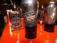
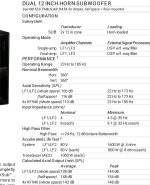
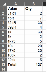
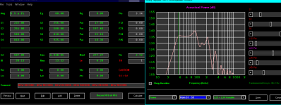
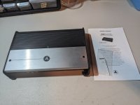
But also in the ears of a professional German Audio-Magazine's editor, who has selected the FC-100 as a reference-amplifier in a given price range (see image #1)
- and who did listen to Mr. Pass' F5, to the SYMASYM to ... but chose the FC-100 as reference!

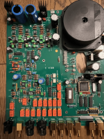
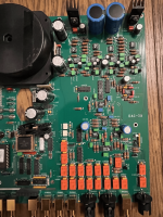
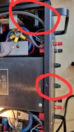
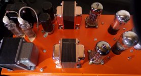
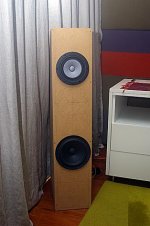
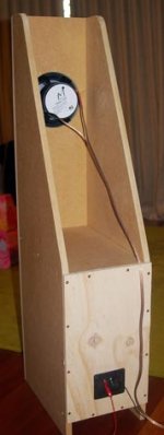
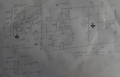
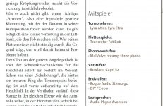
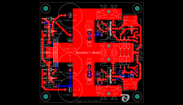
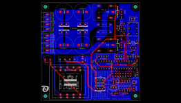
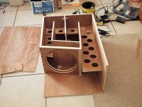
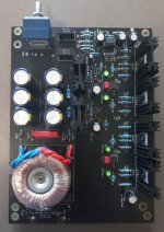
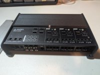
I have only done some very slight, "cosmetic" changes to my original FC-100 layout (changing the input connector, the positions and heatsinks of the backend-rectifiers, ...).
"Never change a winning team". (see image #2).

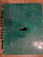
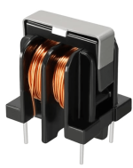
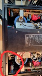
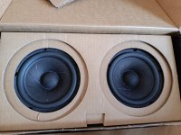
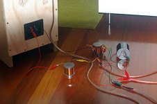
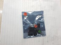
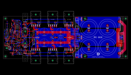
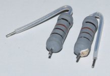
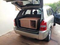
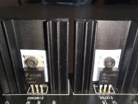
As the FC-100 frontend-PSU I will happily offer you my Dual LT3062-based PSU (see image #3 and the zipped LT3062 - LTspice model).
A German DIY-friend of mine has soldered the LT3062 prototype, being driven from a 2x30VAC EI42-transformer and has adjusted it to give an output of +/-37VDC.
The prototype works flawlessly.

I myself do not like shunt-regulators at all. They are wasting voltage and power.
In the meantime companies like TI and LINEAR have developped very reliable, low-noise LDO-regulators that can/should be used instead!
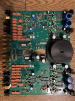
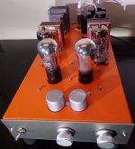
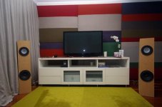
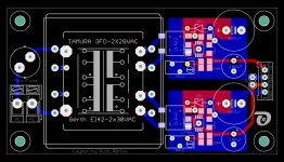
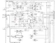
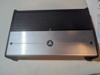
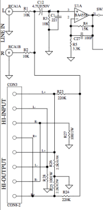
For those, who do not trust my proposed dual LT3062 - regulator, I will offer Mihai's original shunt regulator (see image#4).

If you want the FC-100 to be driven from a "Soft-Power-On Circuit", I will offer you my "SPO/TempControl" - PCB (see image#5).

There is constraint though concerning my offer.
You will of course receive my "Builder's Guide", "Drill-Template", ...
But I will only offer the PCBs being ordered and will not offer you "any hard-to-get-component", nor will I select and match any component.

I have in the meantime grown too old to do this for you, but I hope that there is somebody among you, who takes the lead and tells me:

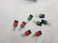
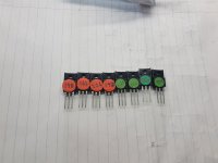
"I will order, select and match the NJL-transistors for you"
"I will order, select and match the input 2SK170 - transistors for you"
"I will order the 2SC3423 / 2SA1360 and MKP1839 and MPC74 - 0R1 resistors for you"

I will support him as much as I can.


Best regards - Rudi_Ratlos

Attachments

  • FC-100 003.jpg
    FC-100 003.jpg
    148.5 KB · Views: 3,800
  • FC-100_AMP_R1_topview.png
    FC-100_AMP_R1_topview.png
    200.5 KB · Views: 3,806
  • LT3062_DC2177A-B_TA01.zip
    LT3062_DC2177A-B_TA01.zip
    1,011 bytes · Views: 453
  • topview.png
    topview.png
    154.9 KB · Views: 3,606
  • FC-100_shunt.png
    FC-100_shunt.png
    179.1 KB · Views: 3,507
  • SPO_topview.png
    SPO_topview.png
    183.1 KB · Views: 3,460

Need help understanding Aikido Preamp

Hello:

A while back I've built an Aikido preamp using 6N2P and 6N1P tubes. This preamp has a lot of gain which is desired since it's used with a custom DAC output of about 75mV. I've played around with different Rk values as well as several different octal tubes and come back to this tube combination. For my system it sounds the best and I have no complaints.

My problem is that I don't fully understand the schematic as it's not the traditional tube schematic.

When trying to establish operating points of the tube in the first stage, do I use V3.1 or V3.2? Does tube V3.1 act as the plate resistor to V3.2?

Thanks
AikidoCircuit.JPG

Reconstruction filter: how much attenuation is the minimum?

The raw DAC output has image frequencies above the audible range. I read the necessity of reconstruction filter so that:
1) The tweeter doesn't get needless frequencies and get its maximum power limit reach prematurely.
2) The intermodulation caused by nonlinearty of the amplifier and the speaker can generate audible frequencies which makes it sound harsh.
I see from graphs, -50db is applied in the non audible range, how much is minimum acceptable?

For Sale Complete and Tested Miro PCM58P DAC

SOLD


For sale is a set of Miro PCM58P Dac board.
You need a PSU (+/-12V and +5V) and I2s source (Amanero USB-i2s, JLSounds i2soverUSB are some examples) to feed it in order to play music.
Look at the info in the thread to see the PSU requirements and information on the DAC board.
https://www.diyaudio.com/community/...s-input-nos-r-2r.354078/page-232#post-7085999

Board fully populated with good quality caps eg. Elna Tonerex, Nichicon FG, Vishay and Epcos film caps, all the signal resistors are low noise non-magnetic resistors with copper leads, good quality Nextron IC gold plated contacts sockets.

This is one of the spare board that i have built. All components, including the PCM58P Dac chips are bought brand new. They are populated to commission the board.
The only exception is the pair of OPA627 op amp, they have been used for quite some time for my other DACs. They are genuine , functioning as they should.

Some people in the diyaudio.com said they prefer PCM58P than the PCM63P. To me the PCM58 sounds sweeter, slightly more detailed and open than the PCM63.... But the PCM63 has a warmer sound, and has a tighter bass. However, as what most members experienced in the very popular Miro DAC thread, op amp rolling will usually settle down certain IV op amp preference on different DAC. It is fun to experiment.

As usual, i usually build more than one board and will keep one for myself.

Price is $140USD, including shipping registered worldwide. Paypal Family and Friends only please.
Check my track records in this group. Shipped over 40 packages to US, EU and UK without any issues. All are happy buyers.

For Sale PCM63-K, PCM1704U-K, SM5842, CS8412 etc...

Selling PCM63P-K, SM5842APT, CS8412, Sanyo OS-CON 680uF 6.3V

Selling my collection of DAC, receiver, filter chips

These chips are NOS and unused.

DAC
Burr Brown PCM63P-K
Made in Japan with 1996/1997 production codes.
Asking $40 each

Other Burr Brown DACs
PCM64P - US$3
PCM58P - US$3
PCM61P - US$2


Digital Filter
NPC 5842APT US$50

HDCD Decoder
Pacific Microsonics PMD100 - US$40 (very limited quantities available)

Receiver
CS8412-CP - US$15

Capacitors

Sanyo Oscons SP 680uF 6.3V - US$0.50 each (about 200 pieces available)

Attempting to install and use CamillaDSP on Debian

I'm attempting to use CamillaDSP for the first time, as an active 3-way crossover and probably to smooth & flatten the frequency response. I shall also be using it on Linux, with which I'm a relative novice. My starting point is (current) Debian, set up as a virtual machine (KVM/QEMU) with USB pass-through to a Topping DM7 8-way DAC (this works fine, simply playing direct to the DAC). The source will be any application (browser, player etc) that is running on the PC.

There is lots of useful info on Henrik's github site. I also found a tutorial on audiosciencereview for setting up a raspberry pi, which I had a go at adapting, but that might be out of date as CamillaDSP objected to some terms in the example config files. But anyway, I gather the process would be to install any dependencies, set up a loopback as a source, and make a config file for Camilladsp to call.

My initial uncertainties are:
  1. If I use the pre-built executable (camilladsp-linux-amd64.tar.gz), which dependencies and prerequisites are needed?
  2. Henrik is doing great things developing a new version; if I'm to learn how to use CamillaDSP, would it be better to use this new version even though it is still in alpha release?
  3. The gitub config page involves setting things up as a systemd service, I've not seen this mentioned by many people using CamillaDSP; is it a necessary step?

Thanks!
Kev

Protection mode of CA Azur 540A V2

Hello everybody,

I have a problem with my CA Azur 540A V2.
If the amp is switched on, the Protection mode takes part at once.
The protection LED constantly flashes in single bursts.
Anyone an idea, why does it happen?
How I can follow the fault in the unit, when the protection mode turnes the function off?

I beg your pardon for my english

best regards
Wolfgang

Strange Problem With A Newbie's New Vintage PA Amp Project.

I realize that perhaps this could be brought up in a different part of the forum. Please pardon me if this is problematic. I have posted before concerning this project before but can't seem to find where I left off. I purchased what was advertised as a Bogen CHA70 PA amplifier which was actually a CHA75a. I had posted about it before I had received it and some had told me it must be a CHA75a. I thankfully received a link to Electronic Service Manuals.com where I was able to buy a schematic for the correct model for $5. I checked it out and it shows a very "busy" looking circuit with 4 X 6AV5Ga output tubes and some others that I have not seen before. The gentleman who gave me the schematic link told me that it must be a CHA75 and would have 2 X 7027a output tubes!? There have been several others who have also told me that it should have the 7027a's and LO AND BEHOLD, when the amp came, that is exactly what it has! I bought the amp to modify into a guitar amp although it has already had some mods to this end. I wish that I could get a schematic that actually corresponds to what I have, although given time I can get it done.
Does Anybody Have An Idea as to why I have a Sam's PhotoFact schematic that plainly states it is for the CHA75a when the amp in my possession plainly says, right on the front panel the same thing, yet there is such a BIG difference in the circuit.? The tubes on the schematic are as follows: V-1, 12AX7, V-2, 6AU6, V-3, 6U8, V-4,5,6,&7, 6AV5GA, V-8, 6CM7, V-9,10,&11, 5Y3GT.....Now, the amp I actually have has the following, and please pardon the lack of proper numbering of tubes here: 2 X 12AX7, 1 X 6AV6, 1 X 7247, 2 X 7027a, & 3 X GZ34. I realize that this is all probably moot to those here who have much more know how than I do, but I am really curious as to what the deal is, even more than I would like to have the correct diagram! Once again, apologies for the posting improprieties....I Will learn.

F4 Amp Upgrade? Best "300B-like" Line Stage?

I have a stock First Watt F4 amp that I may want to use for driving my forthcoming ~ 94db speakers. Presumably by now, there have been quite a few basic mods done on this amp.

But what are those which most listeners found made the biggest improvements to the F4's clean but tube like sound quality?

My other goal is choosing a line stage for maximizing the chance for the F4 to sound like the best 300B amps. http://www.airtight-anm.com/components/atm300.html

In the F4 manual, Nelson Pass said that he had no problem powering his 94db speakers in his 11K cu ft room with 5 volts driving the F4. As my room is only 2300 cu ft what tube amp line stage will help me achieve the best 300B-like sound from the F4?

OR, should I forget the whole thing and pursue a V-FET amp??

BPA200 (LM3886TF) Detailed Diagram

Hi to all;

I'm student from the Philippines, I'm taking up two courses BSCS(Bachelor of science in computer science 3rd yr.) and ECE 2yr student,as of now I just experienced how to make a project using microcontroller, creating firmware and ide software, interfacing nokiaLCD and others,

I want to exercise my knowledge to the next level, since we're on simbreak, I want to Build DIY amplifier, I have alot of reading about BPA200 using LM3886, but I have no luck in searching the complete detailed Diagram.

can anybody here give/send to me the copy of complete schematic of bpa200 using lm3886. thanks

any comment(s) is really appreciated

here my email: cresswood2@gmail.com

Pure silver foil for Hi End cables

Hey Guys,
I need your advice&instructions.A friend of mine can get me 5N silver foil which I think best suits for interconnects and power cables .It can be either 1.5m"m*0.05m"m or 2.5m"m*0.3m"m which size is better suited for IC or power cables or by any chance for speaker cables ? Could anyone instruct me how to coat&shield these 5N silver foil to perfection if I want to build few pairs of 1.25-1.5m for XLR digital and analog interconnects&power cables as well as speaker cables if possible with either of the above sizes ?
The 5N silver foil is quite expensive,but I've read that once it's built properly-you forget the issue of cables once for all !
I'd be grateful to get any pertinent assistance.

NSD106 transistor equivalent

Hello, I am troubleshooting an amp and came across a positive pre-driver that is leaking. It is a Crown D150a and the part number listed in the service manual is NSD106. I am not seeing or finding this anywhere, or an equivalent listed either. Does anyone know what my options are, or maybe I am not looking in the right place. Digikey and Mouser have no results, even as a last resort checked eBay, nothing.

This did not give me anything close:
Bipolar Transistor Cross-reference Search | Equivalent Transistors (alltransistors.com)

Any help would be super! Thank you!

Brian Steele's tapped horn with Skar Audio DDX12

Hey @maxolini ?

I dont trust that skar driver to not sound like a bucket of 💩(it over stimulates the higher resonance funk in the paraflex stuff IMhO) , but it don’t look too shabby in Brians TH? (I dropped a bit of stuffing in the initial path length to relax the lossless sim and used measured TS parameters)

https://www.skaraudio.com/products/ddx-12-inch-car-subwoofer


http://www.diysubwoofers.org/projects/other/POC3/

Attachments

  • 1D189364-1957-435F-860C-CCB151DB54CD.png
    1D189364-1957-435F-860C-CCB151DB54CD.png
    13.7 KB · Views: 201
  • 700D6206-4FF5-41B2-938C-F17F66D9B01A.jpeg
    700D6206-4FF5-41B2-938C-F17F66D9B01A.jpeg
    59.1 KB · Views: 188
  • 96A45347-64B2-4860-A3AE-6C3EFA99B3FA.jpeg
    96A45347-64B2-4860-A3AE-6C3EFA99B3FA.jpeg
    53 KB · Views: 167
  • 25F834D6-486D-4F07-8452-7A18263742A1.jpeg
    25F834D6-486D-4F07-8452-7A18263742A1.jpeg
    58 KB · Views: 177
  • Like
Reactions: camplo

Modern V-FET Amp Build vs. First Watt F4 Amp Upgrade?

While I've long used Class AB amps, I have a stock First Watt F4 amp that I may want to use for driving my forthcoming ~ 94db speakers. But aside from the F4 needing a line stage of ~ 5 volts to drive it, I wondered if there are current commercially available and/or DIY V-FET amps which may sound better-and also perhaps more like the best 300B or GM70 tube amps.

I've read how many DIYers lament the discontinuation of Yamaha and/or Sony V-FET semiconductors. But if those currently produced V-FETs do, in fact, sound as good as the SemiSouth or other esteemed unobtainium of days passed, which are among the best DIY AND commercial amps that use them?

Synergy Horns-Dayton and PRV.....

Sometime last year I became totally enamored by the Synergy Horn concept after several "a-ha" moments about how Tom Danley's other inventions work (Paraline, and Tapped Horn.) My S.O. (the bestest wife in the whole wide world) gave me permission to build a set of three for the LCR of our home theater. After many...many prototypes, rebuilds, back-tracks and a few choice words they are mostly done. I have Tom's permission to post details of my design, as it's his idea and he has it very well covered by patents.

First...for those that haven't heard a well designed DIY Synergy Horn, or the real deal. Find some. Now. They really are that special. I have a degree in Electrical Engineering and have designed audio equipment professionally on/off for over 20 years. They image better than any other speaker, and there is a precision and clarity that some of the crazy high end magnesium/beryllium/unobtanium based speakers can't match.

So, without further ado here are the basics for each speaker:

4 Dayton Classic 8" woofers, 295-310
4 Dayton Designer Series 3" woofers, 295-422
1 PRV Audio D290Py-B, 294-2833

22.5" Cube
60x60 Coverage Area
45Hz to 18kHz +/-3dB (ish)...more on that later.

I'll be posting the photo's I took during the build and my drawings...but it's going to take some time to put together all the info...so patience is appreciated. Questions are welcome at any time.

Scott

Attachments

  • SynergyFront2small.jpg
    SynergyFront2small.jpg
    532.5 KB · Views: 7,068
  • SynergyClose3small.jpg
    SynergyClose3small.jpg
    413.1 KB · Views: 5,958

Why didn’t my modification follow theory?

I built a closed enclosure with a 10-inch woofer. The enclosure volume is approximately 47 liters. External dimensions are 600 x 290 x 360 mm. The T/S parameters for the driver are as follows:
Fs = 16 Hz
Qts = 0.208
Qes = 0.217
Qms = 0.517
Vas = 8.1 cu.ft
Sd = 51.1 cu.in
Xmax = 0.23 in
Re = 3.6 Ohms

I ordered XPS foam and installed it in the enclosure. I expected the bass response to be boosted because the enclosure volume was reduced, and that the system's Q would be increased, resulting in a rise in bass response, with some trade-offs with deep bass.

However, the outcome has not been as predicted. The bass seemed to be softer. I kept adding foam to the enclosure, and it verified the result. So I took all of the foam out of the enclosure. Then, the bass was louder.

Why didn't my modification follow the theory?

BSR EQ 3000

I inherited this unit, which I thought was just a rebadge ADC ss 310, but the interior has a different arrangment, sort of upside down. Intermittantly makes a low rumble in one channel, not even sure its the eq, as it sits on top of Waynes preamp, which has picked up noise previously (pc psu noise through DAC I think, as rerouting usb to front port mitigated it), speakers are reasonably efficient ( Tekton Lore BE). So i need to figure that out, I'm not a tech though, more of a paint by numbers amatuer. Also would like to swap the red LED's for Blue on the sliders, but I think they may draw too much power. I know EQ's are a polarizing subject, but for me with this system and room, it is so much quicker and easier to adjust some of the low end than a digital solution, which I could use -but not as efficiently. Any thoughts?

For Sale Whammy populated PCB

Hi,

I'm selling a fully populated and working Whammy PCB.
  • Panasonic FC, FR and Nichicon Muses.
  • Transistors FQP3N30 and FQP3P20.
  • AOP TL072 on DIP8 socket.
  • ALPS potentiometer
  • 1% Vishay metal resistor
  • Panasonic and Wima MKP caps
  • 25VA toroidal transformer

Price is 150€ + shipping from France

Regards

Damien

Attachments

  • 20240113_133824_resized_1.jpg
    20240113_133824_resized_1.jpg
    474 KB · Views: 148
  • Tansio.jpg
    Tansio.jpg
    313 KB · Views: 155

  • Locked
How come IEMs and earbuds do not have two signal carrying cables for each channel if an audio signal is AC?

I have just begun my journey on learning about electronics, so please pardon me if this questions sounds ridiculous.

To my understanding, AC signals require two leads, one hot and one cold. So that when the sine wave drops below positive, the cold end instead transmits the negative signal. Now, audio signals to my understanding is also an AC signal, but inside IEM and ear buds cables, there aren't two leads per channel, instead, the usual configuration is TRS, in which tip carries right, ring left, and sleeve a common ground.

This leaves me with the question, how come one cable is able to carry an AC signal?

Thank you for reading my question.

Threshold FET 10/PC with a very strange capacitor arrangement

I've been thinking of selling my FET 10/PC phono stage, and given it's almost 40 years old, thought that replacing the electrolytic caps would help the re-sale value. When I started looking closely at it, to get the values, I noticed something extremely odd.... There are two pairs of 220uf caps, which are wired in parallel, but strangely, their polarities are reversed to each other. So the negative terminal of one, is connected to the positive terminal of the other. You can see in this photo, the arrow pointing to the negative terminal on the left cap, the right one has it's arrow on the opposite side. I have no idea why you would do that?

Attachments

  • FET_cap.jpeg
    FET_cap.jpeg
    486.5 KB · Views: 96

Where to get large aluminum cases for DIY amplifier project?

I am building the ESP high power amp (project 101) which requires fairly substantial heatsinks so I will need a pretty large aluminum case. What would be the best source for those? I see tons of cases on Ebay from China but besides few photos, I have no idea if they are worth it or not. I know that large aluminum case with big heatsinks is not going to be cheap so at least I would like to make sure the quality is good. Last case I purchased on Ebay from China for my preamp was just OK. I still had to enlarge few holes so everything fits properly and use lot of thread locker so parts stay together.

For Sale JL Audio XD600/6v2 6-Channel Car Amplifier

Selling a JL Audio XD600/6v2 that is in mint condition. Comes with original packaging, Allen wrench with baggy and the manual. Selling for $700 or best offer.

Message me if you need more details!

Thanks
1000001022.jpg
1000001021.jpg

Attachments

  • PXL_20240111_233634215.jpg
    PXL_20240111_233634215.jpg
    327.9 KB · Views: 62
  • PXL_20240111_233619932.jpg
    PXL_20240111_233619932.jpg
    373.3 KB · Views: 71
  • PXL_20240111_233538887.jpg
    PXL_20240111_233538887.jpg
    452.5 KB · Views: 67

Convert speaker level stereo to line level mono for sub

I have a Jamo S810 sub which only has a mono line level input and a stereo amplifier that outputs 100W RMS at 8ohms per channel without a sub out. It has a line out but that is not volume controlled. I looked into off the shelf LOCs, but they are at most rated at 40W per channel and then I still would need to down mix to mono. Plus most of the LOCs use isolation transformers, which from my research don't function well at low frequencies (at least not ones that are less than $60).

So I started looking up schematics of subs with speaker level inputs to see how pros do it. And low and behold they use simple voltage deviders mostly followed by a summing amplifier. I even looked at an amplifier (Yamaha R-N602) with sub output and it too just takes speaker level outputs, attenutes them and sums them up using summing amplifier.

However I was able to find examples of subs (Polk PSW10 and PSW202) that don't even use an op amp before combining the signal with line input (attached). So I "isolated" what seemed the inportant parts of the circuit an pared it down to the second attached image. I threw it all together, using 4 27 ohm 1/4W resistors in series instead of the 100 ohm 1W as I did not have those available. And it seems to work. I say seems because I have no way to measure distorsion or any possible negative effects to the sound quality. All I can tell is that the sub produces sound, there is no hum and the amp has not blown up nor is complayining.

I wanted to post it here to get a second opnion on why this might or might not be a good idea, or if I missed something inportant from the original circuit. What is the function of the 100 and 2K2 resistors? Why would they possibly use 220K and 10k for the summing/voltage devider? What is the C1 221 (which I omitted) in the original schematic for?

Then perhaps this could be helpful as a resource for anybody that might be searching for a thing like this in the future.

Note: Despite throwing around terms like "summing amplifier", "simple voltage devider", "isolation transformer", I am not going to pretend I have more than a rudimentary understanding of electronic circuicts. I've learned most of those from my research about this. So wait until others with more experience weigh in.

Anyway, any pointers and constructive criticism are much appreciated.

Attachments

  • Polk PSW10.png
    Polk PSW10.png
    69.2 KB · Views: 330
  • isolated circuit.png
    isolated circuit.png
    17 KB · Views: 296

Does cabinet shape affect bass response?

I've no idea why the shape of a cabinet would affect bass response. Volume is the only significant factor, right?
I ask this question because I've spent a lot of time trying fashion a subwoofer to fit under a bed. I think I'm currently embarking of MK VI.
Cabinet making is not my forte. So it's easier for to use a floor-standing tower cabinet as a base (25 litres). But on reflection I've never met a skinny floor-stander with an impressive bass response.
Has the shape got anything to do with it?

Change gain between speaker and headphones

Hello,

I am using a 10W TPA3138D2 amplifier for my projects, and I would like to be able to use it with headphones as well. However, the output signal for the headphones is too powerful and I would like to find a way to switch the output between the speaker and headphones with two different power levels.

Currently, my system is wired so that when the headphone jack is inserted, the speaker is disconnected.
View attachment 1258355
The signal starts from A+ (amplifier output) and goes to SP+ (speaker cable).

How could I modify the circuit so that I can change the gain and disconnect the speaker when the headphone jack is inserted?

The circuit includes a classic preamplifier based on TL072 that can be modified. Any ideas or suggestions are very welcome, perhaps there is a type of jack input with a different pin configuration, or one that has an isolated switch in parallel, or...

Deck Technics RS TR373 gears

Hello everyone.
I'm simply curious. I have a Technics RS TR373 deck that hasn't been used for a few years because some gears have broken.
I bought them on eBay from someone who makes them in Poland. (there are really few who make replacements).
They are nominated as RXL0106; REM0043 and RDG0206.
My question is, does anyone know why Technics/Panasonic made them from a totally different material than the rest of the gears on the deck and why they crack and break over time?
That detail catches my attention. Could it be to reduce noise?
Another reason?.
The ones I bought are made of polyurethane resin, I think they are stronger than the originals, but harder.
Greetings.

Attachments

  • Technics gear.jpg
    Technics gear.jpg
    170.1 KB · Views: 66
Projects by fanatics, for fanatics
Get answers and advice for everyone wanting to learn the art of audio.
Join the Community
507,660
Members
7,883,044
Messages

Filter

Forum Statistics

Threads
405,974
Messages
7,883,044
Members
507,660
Latest member
AlvianSuryaAudio