I have increased the dynamic range of my distortion analyzer to +/-4,000 Volts. I can now safely measure Beveridge OTL amplifiers at their output.
I put together a sort of 'fake oscilloscope' front end to feed my analyzer. It looks like the input of an oscilloscope and properly terminates any scope probe you wish to use. My probes are 100:1 & rated at 4KV. I'll put up some numbers here in this thread soon.


I put together a sort of 'fake oscilloscope' front end to feed my analyzer. It looks like the input of an oscilloscope and properly terminates any scope probe you wish to use. My probes are 100:1 & rated at 4KV. I'll put up some numbers here in this thread soon.
Last edited:

To date all my bench testing has been without load as I had no idea what a proper dummy load might be. These amps are perfectly happy running with no load, they do not misbehave.
In another thread some values were presented and I'm building one up. 1K2 power resistor in series with .0047 HV film cap. These values from HB himself.
Now there's really 2 amps in there and how you connect the load is a talking point. The ESL panels load across the 2 outputs but I think you can load either totem pole to ground with the dummy and measure it in isolation? Will try this soon.
I've done something similar to measure my ESL63's directly on the amp output or on the speaker stators.
For a single amp measurement I load it with half the stator-to-stator impedance.
I found that a home-made HV attenuator is critical; with the high impedances, parasitic capacitances can mess up the frequency response of the attenuator. The test cable capacitance is also important and after tweaking you should use the same cable every time you use it.
So I did a character run to measure just the attenuator to tweak it with capacitors for flat response before I started measuring the amp or speaker.
What is the impedance of your hv attenuator?
I used 100Meg into 100k as the AP analyzer has 100k input R, so it's 1:1000.
Attached the final attenuator response.
Jan
Attachments
Last edited:
Lot of PS noise. So how much ripple is it on the output in reality and how much comes from the measurement setup? The current spikes can create EMI that is picked up by the measurement equipment. Is all your test wires twisted, and your equipment grounded well?
Sometimes the measurement itself could be messed up. Is all cables impedance matched?
Measuring low impedance current source with high impedance equipment is a bad idea. Be aware of the impedances!
Sometimes the measurement itself could be messed up. Is all cables impedance matched?
Measuring low impedance current source with high impedance equipment is a bad idea. Be aware of the impedances!
Unless you know the freq response of your measurement chain this doesn't mean a lot.
What's the nominal attenuation of your attenuator?
Jan
What's the nominal attenuation of your attenuator?
Jan
Remember a collegue who measured a transient response and get ten times higher expected voltage than expected..
The scope had a coax cable with two bananas... i added a 50 ohm termination on the cable and everything was normal.
That can happen if the source impedance and measurement equipment impedance is decades from each other and the cable has 75ohms impedance... just a reminder.
The scope had a coax cable with two bananas... i added a 50 ohm termination on the cable and everything was normal.
That can happen if the source impedance and measurement equipment impedance is decades from each other and the cable has 75ohms impedance... just a reminder.
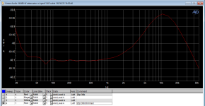
Here are loopback measurements of the test gear - it's flat.
Don't trust these noise measurements yet, I'm not sure where I was re: clipping. Just grabbed a couple quick screenshots.


Don't trust these noise measurements yet, I'm not sure where I was re: clipping. Just grabbed a couple quick screenshots.
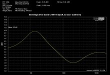
For anyone who didn't know, yes the Bev amplifiers have strong EQ built into them. The frequency response curve above shows truth. Big bump at 100Hz, then a dip at 2KHz.
My 100:1 probe & unity gain buffer should have an overall gain of exactly -40dB. My build has about -41. I got my probe termination exactly right at DC & slightly off at AC which causes this. Not worth fixing in my case.
My 100:1 probe & unity gain buffer should have an overall gain of exactly -40dB. My build has about -41. I got my probe termination exactly right at DC & slightly off at AC which causes this. Not worth fixing in my case.
Not worth fixing indeed. It is flat, that's important, and the -41dBV is easily taken care of in the calculations.
Well done.
Jan
Well done.
Jan
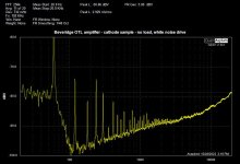
I added a one Ohm resistor to the bottom of one of the totem poles. This serves as a current sample point and was present on the earliest Beveridge schematics. Spectrum analyzing this point reveals something interesting.
This output stage is not push-pull. It is it's own load. The current going thru the tubes to ground goes up with increasing drive, even with no external load connected at all.
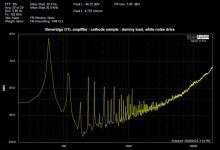
Now, with a pure capacitor external load (ESL panel) you expect this current to go up with frequency as the impedance of the panel heads down and it does. But this treble-heavy current spectrum also exists when I disconnect the load. The 'waste' current thru the tubes straight to ground is also way higher at high frequencies. I find this surprising, I sorta expected that to be spectrally flat? Need to think about what it means.
These graphs are very noisy but the HF slopes are the talking point.
This output stage is not push-pull. It is it's own load. The current going thru the tubes to ground goes up with increasing drive, even with no external load connected at all.
Now, with a pure capacitor external load (ESL panel) you expect this current to go up with frequency as the impedance of the panel heads down and it does. But this treble-heavy current spectrum also exists when I disconnect the load. The 'waste' current thru the tubes straight to ground is also way higher at high frequencies. I find this surprising, I sorta expected that to be spectrally flat? Need to think about what it means.
These graphs are very noisy but the HF slopes are the talking point.
Attachments

Last edited:
The output stage contains two "hidden" capacitive load: heater coil stray capacitance of the upper tubes and the SRPP-like upper tube section's cathode complex, which is degenerated by shunt capacitor. This capacitor determinates the corner frequency of transition between active CCS and fix-biased behaviour of upper tubes with own internal capaciances (G2, G3 to anode for example). These hidden capacitances are comparable the panel capacitances (and give the arteficial protective effect for opened mode drive as quasi dummy load).
Hmm, yes the upper tube filament winding must AC couple to ground at the transformer core. Gotta be in the pF range; I wonder if I can actually measure this with my LCR meter - I'll report back.
Here's proof you are correct: Beveridge transformers sing! Easily audible when bench testing. That winding is being driven with audio to some extent.
OK let's talk about the tilted current spectrum with no external load. Yes the transformer is doing this, I see it now as an un-detachable internal load. It tilts my current spectrum up as frequency increases.
Cathode shunt capacitor: I don't follow your description, transition to fixed bias? However, increasing this capacitance would tilt my current spectrum down as frequency increases.
See where I'm heading? Why is that cathode capacitor even there, what job does it have? Perhaps it is meant to zig when the transformer zags and cancel out some of this tilt?
Final point: This amp I measured has an aftermarket transformer! My other amp has an original and now I wonder if it behaves different when examined in this very specific way. Thank you for your insights.
The filament coil capacitance can be n*100pF generally.
C202 (C204) is 470pF. This is connected series with tube internal impedance (capac. and internal resist. of anode at fixed G1 and G2 voltage).
https://www.diyaudio.com/community/attachments/model-2sw-1-updated-1-29-2020-jpg.1159075/
The tube capacitances and differential anode resistance are paralelled. The tube capacitances are unknown at this type, but G2 and especially G3 (reflector) to anode can show a lot of capac.
IMO it's a sophisticated compensation for closed-loop stability (w/wo external load).Why is that cathode capacitor even there, what job does it have?
- Home
- Loudspeakers
- Planars & Exotics
- Measuring performance of the Beveridge OTL amplifier