For Sale Transistors

All parts are NOS and genuine. PayPal. Shipping - First Class package with tracking /
delivery confirmation. Here the list of countries with International delivery tracking
service (excluding unfriendly countries):
https://www.usps.com/international/first-class-package-international-service.htm
Postage to:
USA - 6$

Canada - 17US$
Europe - 18...19US$
All parts are stored in conductive foam. LIST IS CURRENT.

Dual:
2SK270A -BL, -12, $10/ea, better than 2SK270=2SK389
2SK332 -E, -12, $8/ea, (2SK222-E×2, LN, Sanyo) -better replacement for 2SK117•K184•K163
uPA63H -L2, -12, $6/ea

UP07 -C, -22, $3/ea, TO-126-insulated, 100V, several W power, (4-12mA)
UN07 -D, -14, $4/ea, TO-126-insul, 100V, (8-24mA)
2SJ32 -B, -8, $3/ea, TO-39, 150V, (5-10mA)
2SK121 -"2", -6, $2.50/ea, (2.7-5.5mA), Sony, update for 2SK43
2SK163 -K2, -6, $3/ea, (3.5-6mA)
2SK163 -M1, -5, $3/ea
2SK170 -BL, -2, $4/ea
2SK223 -E, -12, $2.50/ea, 80V
2SK369 -GR, -6, $5/ea
J177, Siliconix, -30+, $1/ea

Small capacitance MOSFET -$4/ea:
2SK511 -6, TO-126, Vgs on these 4V+
VN88AFD -8, TO-220, Vgs on these 2V+
2SJ77 -18, TO-220
LND150N8 -8, "big" smd with tab for heatsinking, $2 for 2 pcs, $6 for 8 pcs

BJT:
TO-126, $2/ea
2SC2682 -Q, -4
2SC2911 -R, -10

TO-92L -$2/ea:
2SA1208 -T, -3
2SA1370 -E, -12
2SA1460 -L, -10 + 2SC3733 -L, -10
2SB605 -K, -6
2SB716 -E, -2 + 2SD756 -D, -2

Advice for multimeter

Like many on this forum, we accumulate measuring devices over the years, always claiming that the last one brings a plus !

There is a time when you turn on your appliances just to maintain the capacitors, it's time to make room (for the satisfaction of wife as well). 😉

So I intend to swap two or three units to only one bench multimeter. Criteria is precision, 4 wires and visible display (with age !)

HDM3065B seems attractive but I don't know Hantek brand...

Any advices ?
Thanks.
  • Like
Reactions: walangalam

T25A Simple Waveguide Profile

Recently @hifijim started a new project involving the Bliesma T25A tweeter, as part of the discussion I offered to see if a simple small waveguide could be simulated. Jim has decided against the use of a waveguide for perfectly understandable reasons. I don't have a T25A myself and so I haven't created a printable model of the profile to test. There was some interest shown in that thread for the waveguide profile to be posted in a separate thread, so here it is.

The Bliesma aluminium drivers are very tall and require a different profile than many modern waveguides aim for in order to avoid ugly cancellations in the very high frequency range. I tried a number of variations on a theme in Ath to see what I could get, but it was not easy to find a profile that did not have some kind of downside to it.

I've simulated many CAD drawn profiles for the T25A in the past and so that is the route I tried next. This should hardly come as news or any kind of discovery as it has been known for a long time that dome tweeters almost always work in a waveguide that uses a section of a circular radius for it's profile. This does not have as dramatic of an effect on the directivity as OS or other proflies can have, but it is that property of not doing too much that allows it to work almost as a universal profile.

It is very simple to draw in a CAD program. I use Fusion and will outline how to use that program to draw it, but the principal could be applied to any other program.

This waveguide is thin at 6mm and relatively small at 104mm in diameter, similar to a standard tweeter faceplate.

I first draw a circle on the XZ plane that represents the throat, in this case it is 29.7mm, using a slightly higher value of 30mm might be preferable depending on the properties of the material being used to print it.

Sketch overview.png


A new sketch is drawn on the XY plane and the previous circle is projected into this sketch. I draw a construction line straight up at the depth of the waveguide in this case 6mm. I then draw another line across at a 90 degree angle the distance of half the overall diameter in this case 52mm. I then draw a 3 point arc between the projected throat, the outer point of the waveguide profile and the last point just needs to be below the top construction line. With practice you can place it so that tangency is already enforced, but if not use the sketch constraints to make the 3 point arc tangent to the top construction line. You can check if this has worked by extending the arc all the way around until it becomes a circle. In this case the 3 point arc as drawn has a radius of 118.01mm.


Profile sketch.png


The centre point of the circle that is the radius can be see by zooming out the sketch, it is highlighted in yellow

Screenshot 2025-01-27 at 2.40.58 PM.png


The same principal could be used to create a deeper and larger version of the same thing, there will then be a bigger effect on the overall directivity. This may not be a good thing for the T25A, but if the same ratio is kept between depth and outer diameter I would imagine it could be scaled up without creating negative interference. I haven't tested this so I cannot say exactly what will happen.

I have attached the surface profile as a zipped step file in case anyone wants to use it as is to create their own printable model.

I have attached the simulation outputs based on Jim's baffle. It is more consistent and even than a bare driver and given the size constraints, it fit's on the same diameter as the driver or can be made to. These are non normalized and show 1500 to 15K 0 to 90 degrees in 10 degree steps. The response is pretty much within 1 or 2 dB 0 to 40 degrees and is an even 10 dB down across the board at 90 degrees vs 0.

H Non normal 0 90 10 degree steps.png


There is diffraction on axis because this is a BEM model with fully reflective boundaries. All sharp edges and creases on the baffle of which there are a few that are also symmetric show the worst case scenario. A real wooden baffle with smoothed edges and a less symmetric profile would offset this to some extent.

0 degrees on axis.png


By 15 degrees off axis the response is a pretty smooth downslope

15 degrees off axis.png

Attachments

Yet Another Transistor Phono Stage, or Going crazy with discrete opamps

Some time ago I had an idea to build a discrete phono stage using bipolar power supplies, but did not really know where to start, so I decided to implement it as a discrete opamp.

I started with this image from Wikipedia showing the basic topology of a discrete opamp with complementary LTPs at the input:

basic_discrete_opamp.png


This was the first version of my discrete opamp:

discrete_opamp_v1.jpeg


To my surprise, the simulation worked at the first try, but it was not particularly impressive. So I started thinking about improving its linearity. Douglas Self in Small Signal Audio Design says that the two things that help the most are:

1) unloading the VAS by implementing an output stage;
b) improving the linearity of the input stage.

My next step was to add an output stage. Dominant pole compensation was moved from the input differential pairs to VAS (screenshot from QUCS):

discrete_opamp_v2.png


These changes, together with adding emitter resistors to the LTPs, reduced distortion by a factor of 15, but it was still not good enough. I ended up replacing tail resistors with constant current sources. Also had to tackle some small capacitors onto the LTPs to make the circuit unity gain stable.

This was almost the final result (shown here with the RIAA feedback network):

discrete_opamp_final.png


I showed it to a friend who is an electrical engineer and a passionate audiophile and he told me that it looks "like an improved version of Acurus P10" :rofl: I was really disappointed because I had been so proud of myself...

Anyhow, I designed a small one-channel PCB. Here it is shown built as a simple flat gain stage (no RIAA network):

flat-gain-block.jpg


I later configured it as a unity gain buffer by removing R14 and confirmed that it was, in fact, unity gain stable. I measured 0.0006% THD at 1kHz into 2K load, but my audio interface is an ancient EMU 0202USB which is only capable of about 0.0005% THD in loopback. Which means that the performance of this gain stage is probably somewhat better than that, but since I can't measure it, I am not going to make any claims about it. I did not match the transistors in LTPs by Vbe and hFE, instead I simply took 6 transistors in a row from the same ammo pack for both NPNs and PNPs. The worst DC offset at the input that I measured was about 15mV after an hour, which is definitely not fantastic, but also not a huge problem (at least not to the extent that it would interfere with the normal functioning of the circuit).

Two channels configured as a phono preamp, powered from a very audiophile PSU, and with suitably high-end wiring to boot...

2-channel_phono.jpg


I won't show all measurements because I can't get rid of a ground loop somewhere, but this is the frequency response (measured using R. Williamson's reverse RIAA network):

frequency_responce.png


It works well and sounds great!

Later I thought: "Gee, this discrete opamp thingamajig seems to perform rather well, why not try using it as a regular opamp?" The result was this terrible little thing, with more robust output transistors and the optional ability to adjust quiescent current in the output stage...

UGM.png


To be continued...

Digital tuner noise

Howdy tubesters!
So I got my first amp working and used a Crate.... what is it called, the wood / composite box with the speakers and the amp... its fine...
Anyway it had a stand alone digital tuner that I incorporated by powering it with the 5v heater line and Cap/Diode voltage multiplier. The lines from the tuner were three, black red and white. I assumed the white is audio in since I could not find any documentation since it is probs manufactured specially.
I tapped the the guitar jack with a 33k resistor and sheilded wire grounded by the jack to the female 8mm mounted on the bottom / back of the chassis (******* weird *** spelling for a word). Problem is when I connect the male to the chassis mounted one a terrible noise is present in the signal.

I have tried a standalone transformer for the thing, and noticed that just having the ****** plugged in to the chassis with no power it makes the noise.
And you will notice at an attempt to smooth the signal with bead and caps....

Any advise would be very much welcomed.

Thanks!

TubiMcTubeface.jpg
Login to view embedded media
digituner.jpg

OCMOS FET

I have seen a schema of optically coupled MOSFET ciruits, as a solid state reay. I saw that Renesas has astory line about isolated mosfet drivers. Some vendors focus on 100kV switching. . . But we need automotive quality like Toshiba's TLP570xH IGBT & MOSFET Isolated Gate Driver.
structural-differences-photocoupler-vs-ocmos-fet.gif
While this picture assumes the mosfets are inside the package,
the following is a driver that needs external Mosfets: VOM1271.
VOM1271.webp
Just. Four pins!
VOM1271T.png.webp
Drive a single or back-to-back N-mosfets (sources combined).
"Unlike conventional MOSFET drivers, which require an external power supply to provide VCC and or VDD rails to the driver itself, the VOM1271 obtains all the required current [=voltage] to drive its internal circuitry from the LED current on the low voltage primary side of the isolation barrier." The cell generates the voltage to turn on the mosfet, up to 8.4V.

The essence is that the driver signal is totally isolated from a power line. useful for switching power lines. Or. For instance as speaker relay, as it can handle AC. They handle 40A both ways. With <5mOhm resistance, and "<-90dB distortion".
My interest is as follows: I want to have an amplifier with on the one hand an F4 (no gain, no pain) and also an F8 (my version of a SIT follower, no gain, lots of pain). [My F8 is a mash-up of for example ZM's BJT version; I choose the nice 2SJ74 as input, maybe should call it J2/F8 to make things more complex; See attached. 2.]. . . Essential: Same power lines as F4 (25V).
  1. I envision to be able switch between the two, by swithing the V+ and V1 alternately, and I do not trust a relay DT enough for that. And then also switch the output.
  2. + Luxury option: on DC, disable the output. . .
Bidirectional looks like this :
PWM coupled switcher (Arduino).png but this board is not isolated. GND is common ground. But it probably is bidirectional, having two fets back to back. So that one extra component is needed.

An example of a driver that is isolated, is: VOM1271 (Vishay) = Photovoltaic MOSFET Driver With Integrated Fast Turn-Off, for Solid-State Relay. There must be more.

  • Any experiences with this use-case?
  • Suggestions?
  • Experiences?
The nice thing would be that the logic is very simple: just run three leds one part (being the F4) and three leds the other part (the other nogainer).

Attachments

  • Like
Reactions: Remnant Parts

Best 3'' speaker driver for small guitar amplifier

Hi,
I am making a small cabinet for my little guitar valve amplifier (1W of power).
Usually, in this size, the sensitivity is pretty bad except for the 2 drivers below:


I like to play rock/hard-rock but not metal!
Which one do you think suits my needs best?
Kind regards,
Pedro

For Sale 2 pair of full RCA BA-21A (made by UTC) transformers

Hello,
Iron ( input and output transformers) from RCA BA21-A.

Those module were used in broadcast/radio console from 50's ( BC-5A) as either mic/phono amps or passive mixbus amplifier. They offered a fixed +40db gain and a max output of +18dbm, with input impedance of 37,5/150/600ohms ( input transformer configuration defined) and 150/600ohms output impedance ( here again defined by transformer configuration).

The original modules are based on 6072/12ay7 tubes ( a pair by modules) and use feedback through output transformer tertiary winding. Those one are special and are (very) rare.

The 'sound' of the BA-21A modules come from these 2 heavy pieces of iron.

You can find every info needed to build it here (technical manual):

https://www.steampoweredradio.com/pdf/rca/manuals/RCA%20Type%20BA-21A%20Pre-Amplifier%20Manual.pdf

The RCA reference number for this transformers are: M-8366 for input and M-8367 for ouput.

M-8366 is an UTC A-10 derivative made to RCA specification.
M-8367 doesn't have sibling i'm aware of: it is speced to be driven by a pair of push-pull 12ay7/6072 and offer 20db feedback through tertiary feedback.

Overall the circuit is on the 'clean' side ( i heard original module+psu used as mic preamp in studio sessions years ago and loved it) because of feedback and regulated psu.

You can see and listen a pair here:

Login to view embedded media
I was lucky to be offered some some years ago, as those are scarce items as the consoles they were used in had been put into junkyard when transistors was the 'new flavour of the day' and anything vaccum tube had to be discarded during 70's, and being located in EU they were even more rare.

I initially bought them with the will to make an MC phono preamp ( 2 in serie (80db gain) minus 20db loss for riaa between the two modules) but these won't happen so some are on sale here.

I'm ok to let one pair ( 2x input and 2x output) go atm.

Initial asked price is 1200euros ( for the 2 set of in/out transformers). Preferably in EU.

If you are interested you can make an offer and let's discuss but don't expect miracles (they are so rare around here) and i won't split a set (in/out).
If you are persuasive i could sell them all...

Thank you watching.

Attachments

  • 103308-a69770f7ff1c0f43446803a39f0d2e7c.jpeg
    103308-a69770f7ff1c0f43446803a39f0d2e7c.jpeg
    328.2 KB · Views: 73

My newest pair of DIY electrostatic panels, advice needed

Hi, last week I finished my fifth pair of electrostatic loudspeakers. (see attachments #5 and #6) I think it's the best effort of my five attempts.

Sensitivity is around 86 dB / 1m / 1 VA / 1 kHz. Outer dimensions are 40 cm x 150 cm. Diaphragm (mylar) thickness is 6 micron and dimensions are 23 x 130 cm. Stator / membrane spacing is about 1,6 mm, a little less than I used in previous models. (about 2,4 mm). I'm aware this limits maximum excursion, but has the benefit of improved sensitivity. I use a custom made 1:125 full range quality setup transformer.

I use loudspeaker screen on the front because otherwise the panels don't fit esthetically with my room. This dampened the fundamental resonance frequency with 5 dB. After fitting a mesh damping screen with a rather low rayle number on the rear stator (on the inner side of the wire stator in order to damp resonances in mid range as well), I got around 2,5 dB more damping, resulting in 7 to 8 dB damping. Resonance frequencies of both panels are 62 and 76 Hz. I guess they will lower a bit after breaking in. I hope they will stabalize around 50 Hz.

I used the software "esl_seg_ui" by Edo Hulsebos to simulate / calculate the electrical segmentation. (see attachements #1)

In the simulation I included the 1 Ohms series resistor between amplifier and audio transformer.

I did extensive listening tests in the room where I built the speakers which is a smaller room than my living room where I put them after they were finished. Bass extension was ok in the smaller room, but in my larger (26 square meters) room at greater listening distance (5 meters from speakers) it feels a bit thin. Not too bad, but I would like to have a bit more lf extension / power.

For frequency and impedance measurements, see attachements #2 and #3.

Instead of building another, larger pair of speakers I was thinking about adding an extra panel per channel which serves as a bass panel to improve bass extension. By putting two panels per channel close to each other airload increases resulting in lowering of resonance frequency. So I'm considering to build another pair with same dimensions and use the same amount of wires (64 per panel) and connect them to the other, segmented panels by adding 1 resistor which makes a low-pass filter. The only possible disadvantage could be that this lf segment is not symetrically on both sides of the main panel, but on only 1 side. Would this be a problem? I made another simulation using esl_seg_ui by adding this new panel by adding one new wire group of 32 wires (2x 32 in this simulation equals 1 new seperate bass panel of 64 wires). See attachements #4.

Included attachements:

#1: segmentation simulation for current panel
#2: impedance and phase measurement in REW, using a custom 1:125 step-up transformer and a 1 Ohms series resistor
#3: frequency measurement in REW with microphone close to front stator (about 3 cm)
#4: segmentation simulation for current + new bass panel
#5: rear side of new panel
#6: front side of new panel

Attachments

  • esl_seg_ui 4_6_24_5m.png
    esl_seg_ui 4_6_24_5m.png
    467 KB · Views: 1,595
  • impedance esl 5.1.png
    impedance esl 5.1.png
    50 KB · Views: 1,460
  • fq esl 5.1 @3cm.png
    fq esl 5.1 @3cm.png
    40.5 KB · Views: 1,382
  • esl_seg_ui 4_6_24_32_5m.png
    esl_seg_ui 4_6_24_32_5m.png
    476.3 KB · Views: 1,713
  • 20210803_105054.jpg
    20210803_105054.jpg
    160 KB · Views: 1,922
  • 20210803_105029.jpg
    20210803_105029.jpg
    129.5 KB · Views: 1,479

Tips, tricks and what not . . .

Hey everyone, Was just down at the bench wrapping up my pearl 3 kit before the chassis gets here plus a F5 duel rail power supply. Trying to decide which boards to build first for it (aleph 30 classic or M2x). Some quiet time got me thinking - Had a few totally random questions for the guys "in the know" . . .

Who makes the best / solid / decent of the following:
(Getting tired of el cheap-o amazon / big box stuff and would like to up the enjoyment factor / minimize the PITA factor

  • shrink wrap tubing
  • crimp on spades / rings
  • crimp on crimping tool
  • automatic wire stripper tool
  • best electrolytic caps (ha, just kidding)

What, if any, precautions do you take for grounding / static mitigation while working with the various semiconductor components?
Is it recommended to use a clamp on heat sink for these little guys or just be mindful of temp / solder time?

What's your personal favorite trick / tip you've picked up over the years of building?

As always, truly appreciate everyone's input- you guys are more than generous with your knowledge!

Cheers!

CS8673E Engineering/Development Thread

Disclaimer - I am NOT an EE!

Backstory: after buying a handful of "TPA3116 D2" boards from AliExpress and having to modify a couple (for soft-on functionality)... I quickly discovered what many others likely have: that those boards are not real TPA3116 bords. Instead, they use CS8673E chips with "TPA3116" stamped into the top of the chip. It took some time of me poking around the interwebs, AliExpress and various chinese sites to track down what actual chip these knock-off boards were actually using.

As I have previously mentioned - these chips actually sound better to my own ears than the TPA3116. But this thread is NOT about the comparison of this chip -vs- others. The point of starting this thread is so I can compile all the info that seems to be missing about these chips into one spot for others to digest and have access to.

The chip itself requires very few external components (not even sure a buffer op-amp is needed!). They will operate on a very wide range of voltages, have all the same protection as the other TPA amps have, and will put out an honest 45 watts of real power when you give them the voltage they need.

The only info I really found for them was a single data sheet entirely in Chinese. First thing I did was translated the datasheet PDF into english the best I could.

But I wanted to tinker with these chips in some of my hand-assmebled proto board projects. So I went on a search for ESOP-16 adapters. While some variations exist, I could not find any that included the bottom pad (pin 17 / ground). This is not only important for ground, but also is used somewhat for heat dissipation. So I did my best and attempted to design an adapter in KiCad myself. I am sure it is far from perfect, but it is what I am going to use for my proto board testing.

All files are attached here to the thread.

The ESOP16_DIP_Adapter zip file includes the custom symbol for this chip as well as the footprint. I have printed off tests as well as just etched a board and it lines up perfectly with the chip. The point of this adapter is to basically turn this chip into a traditional through-hole component that will solder down into any normal proto board or breadboard. But feel free to use the symbol and/or footprint for whatever other custom project you may have.

It is surprising that - even though this chip is sold as a TPA3116 by the millions... there are not any real actual boards sold as what it really is (with optimized components, etc).

Also attached to this thread is an SVG of the adapter pcb directly. This is for those who want a no-bs way to JustMakeTheDamnCircuit(tm) without having to install or mess with KiCad, etc. The SVG prints a perfect dimensionally-acurate image on any decent laser printer which can then be used for transfer in order to etch. Likewise, the SVG also opens directly in lightburn and can be inverted to do the "paint the pcb, burn it, etch it, remove paint" method (as I do).

I will soon update this thread with my findings regarding circuit optimization, experimentation, etc. I will also stick a bunch of photos up in the coming days/weeks of what I build for those who are interested. I purchased a couple tubes of just the raw chips - so there will be a lot of trial and error!

This CS8673 chip really is a solid performer. As I have said elsewhere - it sounds very similar to my Rotel analog amps from late 90's and early 2000s. They are dirt cheap, perform well and require minimal external components to implement.

The resources I am posting here come with no warranty, no guarantee and are provided as-is in the hopes others may find this stuff useful.

- Dean

Attachments

Interest? DIY DAC w/DSP

https://www.reddit.com/r/headphones/?f=flair_name:"DIY/Mod"
I'm trying to gauge interest in an open-source project. The basic idea is to use a Raspberry Pi as a stand-alone DAC + PEQ + (optional) headphone amp. You'd be able to not only adjust the DSP settings via a browser, but you'd be able to have knobs on the device for physical adjustment -- volume, balance, bass shelf gain, etc. In theory, you might have up to 8 knobs or 5-6 knobs + push switches. Sure, there are base presets for my headphones, but I grew up in an era with bass and treble knobs, not to mention balance knobs and there are times that I'd really like to trivially adjust things. A bass shelf, treble shelf, the "air" or ear-gain region, etc. Like the Quedelix 5k, you might have a range of presets ("spk" in their lingo) and then use the knobs to add other adjustments ("usr" in their lingo). Feeling like a bit more of a bass shelf on this song or today? Dial that up. Balance got you a touch off now? Adjust that knob.

This leans heavily on CamillaDSP and so far, it's doing its DSP goodness, driving headphone or RCA outputs, rotary encoder knobs are making adjustments to not only volume but DSP settings, playing from local files, network files, or Airplay, etc. It'll hopefully have full USB pass-through (others have this working already -- part on the way), a nice enough interface / configuration to let you customize the what tweaks the knobs do to DSP, etc. The Pi4 is about $50, the DAC board another $20, toss in some encoders and misc parts and you're looking at $100 for a stand-alone DAC w/full PEQ with as many bands and settings as you like.

The Q is - is this the kind of thing that anyone else is interested in and seeing discussed here? Or, is this just a "me" thing? If so, what kind of features would you want available? What would you want physical knobs to be able to adjust? If not, I'll tinker and still put it up on GitHub, but be less fastidious about making others able to easily understand and replicate.
  • Like
Reactions: mordikai

VituixCAD design before PCB build

Would it be possible for anyone skilled with Vituixcad to eyeball my work for errors. I am a newbie. I started trying to design a crossover to replace drivers in nice old cabinets. As a consequence, my cabinet dimensions, including driver hole sizes are fixed. I have done 7 different designs and entered each into LibrePCB and have completed board layout, but have not had any PCB built so far. Being a beginner, it sure would be nice to have a set of eyes on my work before building the PCB.
I enjoy the work and don't want anyone to do it for me, but I've exhausted what I know to check. If anyone would care to say, something like "are you sure you used the right configuration of ...", or "there appears to be an issue on graph x ..." it would be of enormous help. I attached the most basic graphs and schematic of my most likely to succeed version - there's more for the asking.

The drivers I expect to use: Dayton SIG180-04 (woofer) and Tymphany XT25BG60-04 (tweeter)

Since I feel I owe this sight some payback, I created a library of resistors, capacitors, inductors, and a few miscellaneous items - enough to allow others a pretty fast way to produce a PCB in LibrePCB. Unlike Vituixcad, my background favors this latter undertaking. I'm happy to share this library and could use a pointer of how to do it on diyAudio.

Hopefully I've not offended anyone with this post.

Thanks,
Dave

Attachments

  • SIG180-4_XT25BG60-04_3.0KHz Six-pack.png
    SIG180-4_XT25BG60-04_3.0KHz Six-pack.png
    730.9 KB · Views: 229
  • SIG180-4_XT25BG60-04_3.0KHz XO-schema-1.png
    SIG180-4_XT25BG60-04_3.0KHz XO-schema-1.png
    22.9 KB · Views: 231

New to Sub Enclosures. Port mystery

Hey everybody. I'm new to sub enclosures and have been using winisd. I keep getting a common problem with vented, 6th, and 4th order enclosures.

No matter what I do I cannot push the frequency lower. Either the drivers go into overexcursion or the port velocity is too high.

For example, if I make a 4th order, the enclosed volume largely dictates the frequency depth. However, if I make it larger no matter which driver I choose it seems to send it into over excursion down low. The only way to prevent this is a thin port, then port velocity is too high. I also don't know how to stimulate tapered waveguides or flares to make sure I don't wreck the drivers.

6th order just seems impossible for the same reason, but people obviously build them so I must be doing something wrong. Any ideas?

Hello

Hi -

I was trying to thank someone for a very helpful post, but found out I need to introduce myself first. First, I am grateful every time I find helpful information about anything in electronics or car repair online, so there is that. I was a teenager until 1980, and my dad worked at Bell Labs retiring in 1969. So, he was a tube expert, being a ham all the way back to the 1920s. and also having the distinction of being considered the "father" of Single Side Band for ham radio. I received none of his affinity for tube-type design however. Though I do have Dynaco tube equipment, and I made a couple of Bruce Rozenblit monblocks a few years back. I currently am refurbishing a couple of Chimeatron amplified chime units from the 1960's, which use 6AQ5A push pull amps. I dabble in transistors more comfortably than tubes, as well as digital electronics. I have a stash of vintage 7-segment displays in various technologies, and have prototyped circuits for digital clocks for each. Panaplex, numitron, VFD.

Nice to be here, and I am looking forward to being able to post my first thank you.
Don

Looking for direction on how to modify a crossover from single to bi-amp input

Hello DiyAudio,

I recently acquired a pair of Duntech Sovereigns (mid-west US) and am trying to figure the feasibility to convert them from single to biamp inputs. Attached are a few pics. While I have done some basic repairs, I have limited experience with crossovers having this many components. Yikes, they are even on drawer slides.

My wife and I collect equipment from the Sov's era, back when I was school-aged, when seems all the cool kids in the magazines had more than one amp. I have some amp pairs that are not easily bridgeable that I'd love to use with the Sovereigns.

Ask any questions. I'll do my best to respond. Thanks in advance for any input.

MnM
DS Backplate.jpg
DS Backplate Open.jpg
DS Input 1.jpg
DS Output.jpg
DS Crossover 1.jpg
DS Crossover Underside.jpg

Revox B286 Preamp - No Volume Control

A friend brought me his Revox B286 preamp/tuner which powers up fine but has a very low level output. I discovered that fuses on the Line Amplifier card had blown. I replaced them, and all the dreaded Frako caps that Studer/Revox used. I could see input from all sources but no output at the first stage (IC 100/200). I discovered there was no clock data at IC 301 which I believe will step up the volume. Tracing to the Microprocessor board, there is no clock signal at MPU1 or MPU 2.

The DC voltage looks good coming into the chips. I have only repaired gear with discrete components, so this is new territory for me. I do see the crystal for obtaining the clock and believe it is good. I have recently replaced the 7705 reset generator chip (IC2) with no change.

Attached is a schematic. Any help in finding the system clock is greatly appreciated!

Attachments

  • B286 Schematic.PNG
    B286 Schematic.PNG
    741.3 KB · Views: 133

Bose 901 Series III, Updating the Equalizer

Our realtor friend knows my interest in audio, so she brought me a whole Bose 901 Series III speaker set that was abandoned in a property. The 901 speakers were re-foamed, however a couple needed redoing due to voice coil rubs. The set is from 1978, so the equalizer is by now in need of refreshing. I record here the process for the future 901 owner who may find this useful:

Replace all electrolytic capacitors:

There are 10 capacitors to replace, all 35V rated (or use higher):

2 - 470 uF One was upgraded to 3300 uF, other remains at 470 uF, make sure bigger cap clears cover, mine did not!
4 - 10 uF These were replaced with Nichicon FW
4 - 1 uF - these were replaced with film caps, it improved sound a bit

Replace 14 small signal transistors:

12 - BC239, replaced with BC547, available at Mouser.com: NPN
512-BC547CTFR
BC547CTFR

2 - Motorola 2N3906, replace with complimentary pair to BC547, the PNP BC557 - Note pin orientation different than Motorola, turn 180 degrees. These are PNP
512-BC557BTF
BC557BTF

Replace 2 rectifier diodes:

1N4002

After replacements, I noticed residual power noise, that is why I upgraded the 470 uF cap to 3300 uF, and installed a 2-3 watt 0.47 ohm resistor between the rectifiers and the first cap, had to cut the trace. See picture.

Replace 8 RCA phono connectors:

These were upgraded to gold as the aluminum connectors were oxidized and sometimes failing to make a solid connection. Available from Mouser:

568-NYS367-0
RCA PANEL JACK GOLD

1568-NYS367-2
RCA PANEL JACK GOLD

Sound is now crisp and clean with no lose connections. I hope this will help the next Bose 901 Series III owner.

Attachments

  • IMG_1107.jpg
    IMG_1107.jpg
    128.5 KB · Views: 327
  • IMG_1136.jpg
    IMG_1136.jpg
    286.8 KB · Views: 294
  • IMG_1137.jpg
    IMG_1137.jpg
    122.1 KB · Views: 268
  • IMG_1133.jpg
    IMG_1133.jpg
    283.5 KB · Views: 258
  • IMG_1100.jpg
    IMG_1100.jpg
    86.1 KB · Views: 252
  • IMG_1092.jpg
    IMG_1092.jpg
    101.4 KB · Views: 249
  • IMG_1093.jpg
    IMG_1093.jpg
    157.7 KB · Views: 261

Hello everyone

My name is Kreso(36), currently situated in Croatia, definetly interested in audio/chips/circuts and building stuff but it has been a while since i´ve built subwoofers and stuff like that. Back in Covid times i started producing music, mixing and all that jazz until i had to open a few interfaces to see how they work and here we are..

Reading how smart some folks here are got me wanting to participate, so looking foward to learning a lot!

Cheers

Seeking help with PC specs for running Akabak

I hope a hardware (computer) question is fair game in the software tools forum if it's really about running audio design software. I'm considering biting the bullet and learning Akabak to support my speaker design habit, but my home computer is a Mac. I'm therefore trying to determine how much of a financial investment would be required to purchase a (possibly used or refurbished) PC that will run Akabak without being painfully slow, and support Windows 11. Clearly "painfully slow" is hard to quantify, especially because I don't have Akabak experience to calibrate myself on what can reasonably be expected. Any advice on which processors to seek out or avoid, how much RAM is needed to avoid it becoming a bottleneck, pitfalls I might be unaware of, would be appreciated. It's been many years since I had to spec out a Windows PC so online references to "eighth generation i5" are pretty opaque to me. I don't want the PC to become its own project, if I can avoid it. I just want to run speaker design software that isn't compatible with my Mac. I'd also rather avoid a bulky full size tower, if I can.

Thanks in advance for any hints anyone can offer!

Few

Best woofer for 3 way using first order crossover.

Any recommendations for a woofer that can be used in a three way which sounds good using a first order crossover?
For many years I have owned Gale 401s which use two 8 inch woofer in parallel crossing to a 4.5 inch midrange at about 375 hz.There just seems to be some magic in that arrangement that gives wonderful musical engagement ,dynamics and expression.I have tried to replicate that sort of sound in DIY speakers over the years but never quite got there.
Perhaps somebody has found a woofer or a pair of woofers that will work like those old AR types in the vintage Gales? Or a kit speaker like that?

2p: Scan Speak 18W/4531G01 and Bliesma T25S in WG

As I had all the components around already, I was thinking of what to make out of it.
First I had to adjust the opening for the tweeter waveguide.
Prototype cabinets had 25l net volume, so I started with that.
Initial measurements proved the drivers were very linear so they would not be complex to make crossover for.
18W/4531G00 - perfect linear response, very consistent off axis responses, very good distortion (little bit higher H2 though). I added bucking magnet. Ideal for 3k low order crossover.
T25S in WG - generally these small Bliesmas don't like low crossovers and shallow slopes, so the target was at least 3k LR2. WG, though really small, works excellent. Top end is not as linear as in my prototype WG so I will still work on this. Combination of natural rolloff of waveguided response and and just simple crossover allowed 3k LR2 acoustic slope.

I was very pleased to see that this combo works excellent in Vituix even with the simple filters and that phase matching was good.
It has been 2wks since I started listening tests. In the meantime I lowerd internal volume to 22.5l MDF pieces and adjusted Tweeter level. Drivers also burned in so I could conduct some serious listening test to assess if this is worth completion.

So far I am very pleased with how this combo sounds. It is very natural, relaxed and easy to listen, though not too soft, muddy or slow in any way. Bass is great for smaller two way and midrange does not lack anything (this is generally an issue with any 6-7" in 2way when asked to do both bass and midrange right, so it was the reason I lowered the volume to ~22l after initial listening test, and bucking magnet also does its part in midrange improvement). The trebles have clarity (yes, clarity, though this adjective fits more to hard domes) and openess, with no hints of hiss or similar weaknesses normaly related to silk domes. I believe WG does its job well, controlled dispertion in ~3k-7k is always good things when effortless and clear trebles are the goal.

Overall this was very nice to see how all compenents fit together and resulted in great measured and listening results with just simple crossover.

Attachments

  • 20250511_115350.jpg
    20250511_115350.jpg
    51.7 KB · Views: 165
  • v4 crossover.png
    v4 crossover.png
    11 KB · Views: 166
  • v4 spinorama.png
    v4 spinorama.png
    99 KB · Views: 151
  • v4 polar maps.png
    v4 polar maps.png
    215.1 KB · Views: 142

QUAD ESL-63 panel without stator PCB

There is a recently applied patent that takes another very different look at making an electrostatic loudspeaker. Particularly the way the stators are made.
I contacted the patent holder and asked if it was OK to give a DIY approach on his design a go. As long as I was not promoting it commercially he was OK with it.

So here is a short video of the very open design as a proof of concept. Yes it works and it works fine.
Sensitivity is very acceptable, distortion is low, but what is most remarkable and I don't know of any way of measuring that, is how OPEN is sounds. That was also most likely the intention of the design in the first place.
The designer claims a complete break on the relation between open area and capacitance, but that is, sorry to say, not true. There is a fixed relation between the two, but obstructions area is much smaller than with wire or PCB stators.

Took several days of 3D printing the 500+ parts that are in there and several weeks of manual labour to apply and assemble the whole contraption.

Per panel the square space is like a Quad ESL-63 panel. Eventually we want to try and build a complete speaker with 4 of these panels each. The ultimate goal would be to apply the delay rings as well.

Panel size Mylar surface 58x17 cm. That is 98.600 mm2 of surface area.
Obstruction surface is only 18.300 mm2, only 18,5%.
Open surface remaining is a whopping .... well you can see it in the short video.
Stator to stator capacitance is 90 pF.
Diaphragm movement space twice 2,5 mm (also like the Quad-63 panel)

Please note that this is a patented design and done here just for the fun of proving that it can be made with simple means and to have a listen at the characteristics without having to travel half the world to hear the original concept. There are still a lot of thoughts on how to change/improve upon what is demonstrated here.

JBL PTB99HF-1 Waveguide

I searched the diyAudio site for any reference to the 1 inch screw on JBL PTB99HF-1 Waveguide. 6 inches square. 90 x 90 degrees.

I came up empty.

Anyone use it in a project. Listen to it or have anything to say.

I am thinking of possibly applying it as the top end in a bookshelf.

I have a pair plus a pair of JBL 2408H-2 compression drivers to test drive.

I will post some measurements if there is an interest.

Thanks DT
  • Like
Reactions: Arez

AQ1200

What is the best course of action when everything seems fine but there is no audio output?
All drive signals on the outputs look good.
All power supplies are there.
Relay kicks on and amplifier shows a green light.
The only real strange thing I see is there is "ringing" on the signal at the top of R33 on the output card.
Signal on top of R33.jpg

Audio and Chassis Grounding

I use an external soundcard and a pc to measure amplifier circuits. I think I have an issue with audio and chassis grounding.

The amplifier chassis is properly grounded of course. The audio ground and power supply minus are connected to the chassis ground by a 10 Ohm resistor.
A RCA cable or a probe is used to measure the amplifier and is connected to audio ground and audio signal.
The external soundcard is connected to a pc with a standard USB cable. The pc's chassis is also connected to ground.

The issue I'm running into is that the pc's USB connector is internally connected to the pc's chassis (and thereby grounded). So by connecting the USB cable to the pc the 10 Ohm resistor in the amplifier is shorted and there is no longer a separation between the audio ground and the chassis ground. In the amplifier there is a reason for the separation between audio ground and chassis ground. Shorting the 10 Ohm resistor this way seems to affect my measurements.

aarding.png


What can I do to keep the amplifier's grounding intact.

Passive stepped attenuator into Purifi Eval1

Im just starting a build around a Purifi 1ET400A Eval1 as an integrated with a passive 10k shunt stepped attenuator preamp. Confirmed with Purifi directly that this is ok when using the input board in high gain mode.

My source is a Chord Qutest DAC (output impedance 0.025 ohms, unbalanced rca). Ive done this before with an amplifier with an unbalanced input and was really pleased with the results, but im a bit stuck on how best to handle the balance stepped attenuator with the unbalanced source.

Do I run my unbalanced input into a 2 pole stepped attenuator, and then wire that to the balanced input combining the earth and cold signal.

Or take the unbalanced input into a 4 pole attenuator and then to the Purifi.

The former is cheaper using a 2-pole attenuator but feel there are nuances here that I don't yet understand. Help appreciated.

Please help me! Mark Levinson ML 23.5

BITTE HELFEN SIE MIR! Mark Levinson ML 23.5
Mir ist echt ein Scheiße passiert!
Ich habe meinen Mark Levinson ML 23.5 vor 1,5 Jahren gewartet und wollte nun den Ruhestrom überprüfen! LEIDER ist beim Messen ein Unfall passiert!
Irgendwie habe ich mit der Messspitze des Multimeters einen Kurzschluss zwischen dem Leistungswiderstand und dem kleinen gelben 10nF Kondensator verursacht! (siehe Foto)
Er zerstörte den Sockel des gelben Kondensators und meine Messspitze komplett. Laut Messung ist der Kondensator in Ordnung. Und eine 8A-Sicherung war auch kaputt!
Nachdem ich die Platine wieder gereinigt, den Sockel des Kondensators ausgetauscht und die Sicherung ausgetauscht hatte, versuchte ich zum ersten Mal die Endstufe wieder einzuschalten!
Der Schalter beginnt zu leuchten und ich dachte, du hast Glück gehabt. LEIDER FÄNGT ES IM VORDEREN BEREICH AN ZU RAUCHEN!
Natürlich habe ich es sofort wieder ausgeschaltet.
BITTE HELFEN SIE MIR!!
Vielen Dank!
Andreas

Attachments

  • 20231230_131755_resized.jpg
    20231230_131755_resized.jpg
    523.7 KB · Views: 311
  • 20231230_131913_resized.jpg
    20231230_131913_resized.jpg
    310.5 KB · Views: 192
  • 20231230_132019_resized.jpg
    20231230_132019_resized.jpg
    644.7 KB · Views: 226

Tubelab SE choke, run cap, and R6 resister questions.

Hello all I'm trying to finish my TSE build that multiple moves and other real life stuff interrupted. It is the original TSE board which has been populated for a couple of years waiting to be put in a chassis and wired up. It has been set up for 45 tubes.
I have a few simple questions that will help me finish this project.
1-Does the choke get wired directly to R4 pads?
( yes wired in place of R4)
2- Do I need to change C4 if i add the choke? it is currently 47uf 450v and my transformer is 540ct
3-Are there pads to connect the external run cap? I'm a little fuzzy as to where to connect it to the board.
( found in parallel with C5 )
4-and finally while going over the assembly manual I read that R6 was changed to a 6.5w resister, I have a 5w one in my board. I plan to replace it but I am having trouble finding a 6.5w can I use a 7w without causing issues?
( nevermind found a 6.5w )

here are some pics of my board and its soon to be new home. The chassis was my first attempt at veneer so its not perfect. Top plate is 1/8in aluminum which I plan to polish.
Edited due to finding the answers on Tubelab website. Only 1 question left.

Attachments

  • 20250522_215255.jpg
    20250522_215255.jpg
    195.5 KB · Views: 44
  • 20250522_215321.jpg
    20250522_215321.jpg
    204.6 KB · Views: 50
  • 20250522_215342.jpg
    20250522_215342.jpg
    205.7 KB · Views: 46
  • 20250524_105437.jpg
    20250524_105437.jpg
    243 KB · Views: 46
  • 20250524_105456.jpg
    20250524_105456.jpg
    206.1 KB · Views: 46

Hello, I'm Diego from Italy

I'm 52 and looking for information about louspeaker mainly, less about electronics, because I'm not very skilled in that. Happy to learn something about acoustic theory. I built a pair of fullrange voigt tube with TB W8 2145 and a subwoofer in topology 6-th order bp, inspired to project Trentino by Giuliano Nicoletti from many years ago with Ciare loudspeaker.

3 way using a dome midrange

Hi everyone,
Greetings from India. I am planning to build a 3 way speaker in which mid duties will be assigned to a dome midrange. Here only HiVi dome midrange drivers are available as of now and the driver models are HiVi DM7500 and HiVi DMN-A. Here are the links

https://www.parts-express.com/HiVi-...kFDpp9Zt0DNCKtMdpMJ9iVvmUxueAuqZ_uUllAlHjICmS

https://www.parts-express.com/HiVi-...KycU3BsC9FgpnAl8C9StqGE6gZJmukcXDgBdoWn2qz0JK

The woofer duty will be assigned to SB 23NRXS-45 -8. Cabinet volume will be around 38-40 liters tuned to 35-40 hz. Here is the link to the woofer

https://sbacoustics.com/product/8in-sb23nrxs45-8-norex/

For high frequencies, I have two textile dome tweeters in mind. Both are Wavecor tweeters( Wavecor TW022WA05 and TW030WA07). Reasons behind choosing them are good frequency response, nice off-axis behaviour and low distortion. I also have SB29RDAC with me which I bought previously. Here are the links to the tweeters

https://www.wavecor.com/html/tw022wa05.html


https://www.wavecor.com/html/tw030wa05_to_08.html

https://sbacoustics.com/product/sb29rdac-c000-4/


I have planned to cross the midrange with the woofer at around 700-800 hz ( which might be needed to be stretched around 1000 hz in case of HiVi DMN-A). The midrange to tweeter crossover point will be around 4000-4500 hz.

What are the difficulties which may come in case of dome midrange and crossing it over with the woofer and tweeter? My tonal preference is warm detailed midrange and smooth detailed highs. Please help me with your experiences and suggestions which will be much appreciated. Thanks in advance.

Adjusting anode voltage with OPT

Hey guys, I have to adjust a difference of aprox. 11V between anodes of the two tubes, I'm using OPT for each tube but only one SSHV2 for the two OPT.

It seems possible to reduce one tube anode voltage using a RC between the SSHV2 and the OPT?

Using Ohms Laws for 11V & 20mA I need 550 ohms 0,22W so 1or 2 watts will be enough but how to calculate the value of the capacitor to do RC an avoid the resistor used as load togheter the OPT?

Looking for cheap 3d printed MEH

Hello everyone,
I tried to read what I can, but I don't understand hornresp at all. I can do work in ATH, VituixCAD,WinISD and Fusion.
I'm looking for a project/files to 3d print horn that is not bigger than 600mmx600mm. Cheap drivers and polar plots see would be a bonus point. Where I live I don't think anybody have build MEH so I have never heard it. Please help me if you can 🙂
Ultimately I can do some wood work and also I have dipole subs (form LX521).

Help needed to ID SMPS chip

I'm trying to repair the power supply for my Flymo 1200r Robot lawnmower, it went bang big time. Damaging the mosfet, bridge rectifier, fuse, diode and two resistors, I have replace all the damaged parts, but I'm struggling to identify the chip in the photo below marked 01M311, I suspect this is also damaged. I have searched the web but unable to find a supplier or a PDF to find an alternative. The Mosfet OSF10n60B was also not available but made by OCENME which I replaced with a MDF10n65B.

I think it a PWM but not sure....any help or suggestion would be welcomed?

Beau..

Attachments

  • Screenshot 2025-05-28 at 15.22.34.png
    Screenshot 2025-05-28 at 15.22.34.png
    752.2 KB · Views: 64
  • tempImageZrWqEN.gif
    tempImageZrWqEN.gif
    1.5 MB · Views: 62
  • tempImagevcdBhM.gif
    tempImagevcdBhM.gif
    1.4 MB · Views: 60

Assistance with Reverse Engineering Crossover

Hello,


I’m looking for assistance with reverse engineering the crossover network from a pair of speakers. Specifically, I would like to know if it’s possible to create an accurate schematic based on detailed photos of the crossover components and layout. There aren't schematics available online, sadly.


If feasible, I’m happy to provide high-resolution images of the crossover board, including close-ups of the components and their connections. The goal is to document or potentially replicate the design for analysis or restoration purposes.


Any guidance or support in interpreting the layout and developing a schematic would be greatly appreciated.


Best regards,
Michael

Alpair 12p + MAOP 7 Gen 2 ideas

I recently acquired a pair of Alpair 12p's which I had planned to build into Scott's Juliet Double Chamber Reflex design

Juliet-Alpair-12P-classic-DCR.png


I have since come by a pair of MAOP 7.2's which I'm currently running in a pair of Woden baby labs Storm Shadow V2

I'm now wondering about combining the 2 into one WAW design and I'm after any advice/ideas for doing so
This could be a one box solution like Scott/Dave's design for for A12pw and A5.2/3. (Don't know if this could be adjusted to suit?)

Screenshot 2025-05-28 at 13.10.31.png


Or my current idea is to continue with the Juliet build and add a separate sealed box on top for the MAOP - something like the image below - top box would obviously need to be the correct size to suit the MAOP (Which I'd also need some help with along with which type of alignment would be best)

Screenshot 2025-05-28 at 12.15.19.png


Then there's filtering. Run the 12p open and high pass the MAOP? or cross the two over at a certain frequency like a traditional 2-way

or does the sensitivity difference between these two drivers make this whole idea a non-starter? 91.7db for the 12p, 85.8db for the MAOP 7

Any help / ideas greatly appreciated

Need help with crossover for Phenomax midwoofer and 3/4" Revelator

So I've had these drivers sitting around for the better part of a year and finally decided to try simulating a crossover. I don't have measurement equipment so I'm forced to go off manufacturer data. I used FPG graph tracer and XSim. It's my first time doing this. One thing that concerns me is the low efficiency but i think this is a given considering the efficiency of the midwoofer. The other is the 9.1 ohm resistor in the BSC circuit. It seems a little high when i compare it to other designs I see. I've attached a screenshot of Xsim. Any input is welcome!

Attachments

  • Phenomax-Revelator.png
    Phenomax-Revelator.png
    178.7 KB · Views: 322

Hi and LM3875 Gainclone

I'm Peter, from the Netherlands. Some 20 years ago I bought the basic LM3875 kit from Peter Daniel, intending to build the kit as dual mono with my 2 Hypex transformers ( with CT !! ). But these are not like the ones Peter uses and now I didn't know how to handle that. This and 149 pages of info on the kit ( AND other stuff Dac's and such ) on this forum was, at the time, a bit much to distill the needed info from. So it took me 20 years to complete this project. I read about different combinations and placement of caps, snubber, or not to snubber, zobel networks, or not and I got confused and stalled. But than I got a little help from a Dutch audioDIYforummember and was able to use the supplied PS pcb's. Decided to use the standard layout and bought a case and some stuff needed and started the build, which took let's say a week to build. I'm surprised at how good it sounds. It's so simple, so little components used, but sounds really nice. I'm using it with Fostex FE103e horns, I built myself. Really nice combo.

Attachments

  • IMG_20250525_222248.jpg
    IMG_20250525_222248.jpg
    325.9 KB · Views: 30
  • IMG_20250525_191518.jpg
    IMG_20250525_191518.jpg
    400.6 KB · Views: 24
  • IMG_20250525_191451.jpg
    IMG_20250525_191451.jpg
    322.4 KB · Views: 29
  • IMG_20250525_142503.jpg
    IMG_20250525_142503.jpg
    421.9 KB · Views: 25
  • IMG_20250524_203057__01.jpg
    IMG_20250524_203057__01.jpg
    418.6 KB · Views: 23

"Hancocks", another VersaBox build with Dayton SIG180-4 and AMTHR-4...

This is the fourth completed build in my VersaBox cabinets, however, I call it build 5 because 4a (Jaekels) and 4b (Itasca) are yet to be completed. There was a lot of gumption to finish this one first due to interest in the drivers from other parties and builders. So, these were finished out of turn. It started when I was awarded a pair of the Sig180-4 woofers as a door prize about a year and a half ago at the PE sponsored Speaker Design Competition. I honestly did not think it had been that long ago, but they have now been available just a few months longer than I've had them. The Signature line has been met with I feel undue criticism, and I feel they are an impressive set of drivers with good cost benefits. Obviously, the name is a play on Signature, and insisted I sign my Hancock on the bottom line.

Why the AMT?
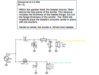
The tweeter choice was from looking at the Dayton offerings and trying to decide what was the "unofficial best fit" as a Dayton Signature tweeter. The Reference Series have their own models, but the Sig woofers are left with them omitted. The Esoteric had one, Euro had one, and the Epique has one coming soon. Heck, even the Classics have the DC28 Silkie and the ND have several models. Since the Reference vs the Signature are 2 of the 3 current upper class sectors, I gathered the inexplicably unattached AMT line was the best direction to go as a different flavor from line to line. That meant the AMTHR-4 was likely the best unit to make an attempt at a 2way here. It doesn't rolloff the top-end like the AMT3-4 or AMT-Pro. It is the otherwise largest and most robust Dayton AMT currently offered that should allow the somewhat lower xover points required in a 7" 2way. Additionally, while I think it does have output to spare, an MTM is out of the cards in this case because the Signature line woofers are 4 ohm nominal impedance. Any thought of paralleling 2 woofers to increase sensitivity is a wash without a 2 ohm stable high current amplifier. Also of note- the resistor across the AMT added considerable damping to their operation, and that is substantial enough to recommend this kind of component addition wherever it is utilized.

About the VersaBox...
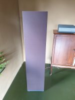
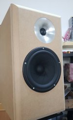
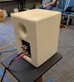
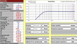
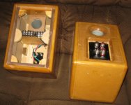
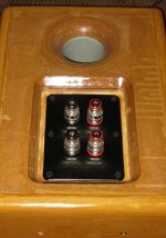
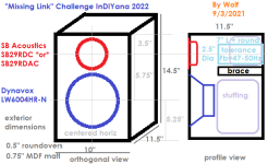
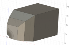
It's a fairly basic 15 liter vented box. There is a rear port with grey 2.5" electrical conduit. One solid shelf brace connects the rear and sides for about 2/3 of the cabinet depth, ending just below the inner port exit. Fb is fixed at 47Hz, yielding an F3 of 44Hz, and so far has been a really good place to tune these cabinets with good results in all of the builds used herein. The front baffle has a 3/4" deep inset mount for an interchangeable baffle which is secured with 6x 1/4-20 furniture style hex-drive bolts. All edges have a 3/4" roundover, and the port has a 1" roundover on the exit.

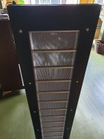
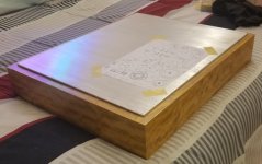
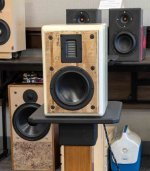
The baffles were originally going to be textured black/white cutting boards, backed to make up the thickness required. Upon looking for the backer pieces, I found a piece of 3/8" thick T111 tongue and groove plywood siding that I had forgotten I had. It had apparently been laid face down and used as a spray paint base or platform at some point. Since the Dayton drivers are purportedly 'Amazingly Affordable', I felt a well implemented piece of scrap wood would give these a very unique aesthetic against the gloss white the rest of the VersaBox cabinets bring to the table.

If you don't read these for woodworking information, skip this next long paragraph about woodworking....
This board had obviously seen better days, and wasn't thick enough for the 3/4" deep recess, but there was enough of it that I could use it with mirrored inherent grooves on left and right adjacent cabinets and have enough for both speakers. I used a piece of 3/4" ply as backer for both, resulting in 1.25" thick boards. Once that was glued, trimmed to width size, and deemed still usable, I gave it a light sanding and used the shop-vac to remove any dust debris or dirt. The board had a void that travelled from one side of the baffle to the other about 2-3 layers down from the face on one end. The middle was riddled with worm tunnels, which my thought was to save as much of at this point. Spalted/Wormy wood always costs more, and it provided a path for stark contrast against the tone of the pine plywood. I made my cut to separate the then conjoined twin boards and salvage the majority of their former pesty lunch travels. I then used West Systems epoxy and some tongue depressors to remedy the void, which involved applying tape prior the pour, and then applying tape on the face after poured because the epoxy was finding gaps and feathering through the surface. It came out okay luckily, just had more fill in some irregular areas. Then I applied a very light coat of the same epoxy to seal the board surfaces using a fake-advertising style fake-credit-card that came in the mail. It allowed a very thin coat and solidified all of the loose or soft fibers in this aged board, and only filled the worm channels minutely so they could still be filled with something else. Sanded and vacuumed yet again, followed by a small chamfer of the face perimeters, and then driver rebates and rear-side reliefs; I came upon a Youtube vid channel I had been watching periodically by Four Eyes Furniture. He was using black glue-sticks in a hot-glue gun to fill voids in a table, setting 321 aluminum blocks on them to cool, scraping off excess with a chisel, and then a light sand to finish it before his final resin coat or epoxy. I thought I could use this to enhance the spalted lines' visibility as contrast, and it worked rather well. I used an old heatsink and pressure since they weren't as heavy as the 321 blocks. I would recommend the low setting on the glue gun, as it is easier to use without drips or stringy problems. I got the glue sticks at Home Depot under the Ryobi brand. Another light sand, and that is where I have them at the moment. They are due to be 'epoxy-carded' one more time with sanding to follow in finale. I hope to be able to leave some texture to the boards as they have a good feel to the touch as they are.

The drivers' characteristics....

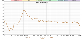
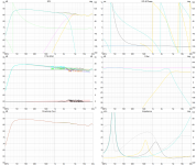
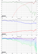
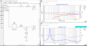
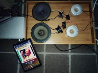
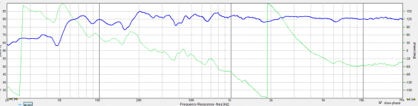
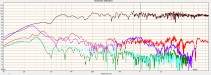
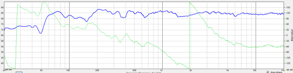
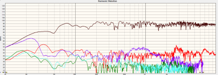
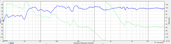
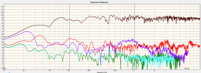
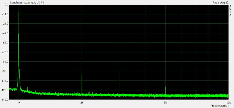
Measuring T/S of the SIG180 woofers, I had a Qms much higher than spec initially. I then remembered to remove the packaging plastic from the backplates and did it again. I still had Qms considerably higher than spec. Even so, the T/S was manageable in a modest box volume, and yielded an F3 that was low enough to be accepted. Doing an impedance sweep with tones for the most part was fine- until the breakup region hit. These drivers have had some lengths taken to try and minimize the magnitude of the aluminum cone breakup areas. As I believe I've read, the voice coil former helps to damp the cone due to the material used. Looking at the frequency response in the spec sheet, the plot rises to a very broad plateau and then dives like an expert in a swimming contest. Due to the assembly as designed, it is hard to tell where the underdamped breakup magnitude would be the strongest were it less well-treated. As the tones were increasing in frequency, 2kHz stuck out like a sore thumb. 3kHz came and went with less bravado. So- how to treat the breakup that doesn't measure or offend where you think it does? Since 2k was brash, I purposely placed a dip in the response there and started the woofer rolloff early. Then I tanked the response at 3k to both heavily damp where a typical breakup is before rolloff, and damp the knee of the total rolloff more heavily. The woofer also has a broad rise in 3rd order HD centered around 800-900Hz. While it looks worse than other supposed better or SOTA drivers, it is at a lower level than -40dB/1% from reference and is really truthfully of no concern.

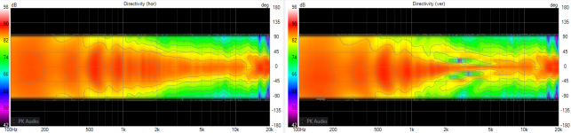
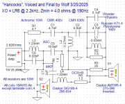
Why did I need to damp the knee so heavily at the rolloff? Well- because as stated the woofer needed it is indeed one reason. The other is due to the AMT and how they tend to work. All tweeters using shallower slopes tend to want higher cutoff frequencies. This is a given. The lower you go, the steeper the slope that is required. Being an AMT, the HD measurements taken and how to best use them, they are limited to about 3kHz with a second order electrical slope. If going to the lowest plausible, the 2.2kHz point requires a 3rd order electrical network- which yields an LR6 acoustic rolloff slope. Due to how the drivers work, where they wanted to meld together automatically made this an LR6 summation.
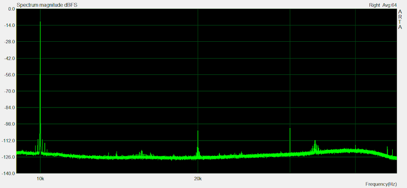
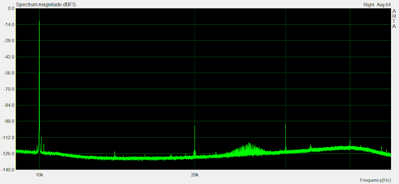
The AMT also had a broad peak centered at 10kHz, which meant it needed suppressed.

Then I put the tentative xovers together, and ran through the bunch of caps I happened to have in the values I modeled. I noticed that they all sounded a little different. Then increasing the first cap from 3.3uF to 4.7uF added the body in the music that was missing. Another round of trying caps in the new value ensued. Such is another benefit or curse of the AMT, as they are resolving enough to tell there are differences. One sounded shrill, one benign, one plucked hard, and 3 or 4 were fine save for some grit in the lower treble. When I finally stepped up to Clarity CMR, the grit disappeared and all was finally well, with nice detail and space of the recording.

Thus far, only a few cap brands/models have done this for me. Jantzen Superior and Silver, Northcreek Zen, Fostex Copper-Mylar, Clarity CMR and MR, Audyn Plus, ASC X386/X387, AuriCaps, and sometimes SoniCaps or MultiCaps. I haven't tried them all, but have more to try. In one of my previous builds called Nephila, the AMT sounded much better to me on the Zen caps over the industrial GE or Arcotronics style caps. The Zen yielded a massive soundstage while the GE/Arco was more focused and less expansive. I was hoping to find the right capacitors to allow lightning to strike twice for me in this build vs the previous of the same style.

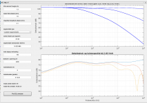
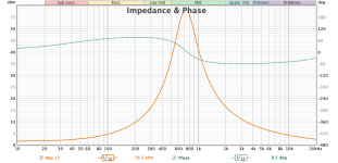
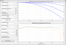
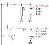
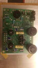
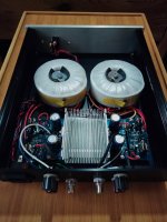
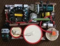
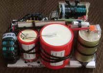
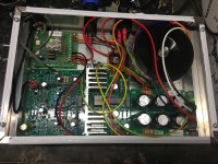
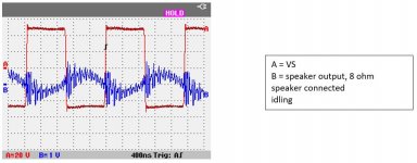
I wound the coils myself from 18AWG Blue (Dry-Oil) enameled wire. It was worth the cost to find a spool of it, as it looks really cool. I know 16 parts is rather high in count, but it was worth it for the results I achieved. As shown, at 1m distance measurement, the HD remains below the 1% threshold even at 100dB output. Zmin is about 4 ohms at 190Hz, and sensitivity is roughly between 86 and 87dB.

Thanks for reading, and additionally thanks to @hifijim for the nudge and push to get this build posted sooner than later...

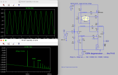
PS- the Missing Link was the first design in this box, so I included the drawing for that build....

Attachments

  • 4xlrz1yq9evf.jpg
    4xlrz1yq9evf.jpg
    66.8 KB · Views: 225
  • 7ulpuhdatvn6.jpg
    7ulpuhdatvn6.jpg
    125.4 KB · Views: 225
  • dvcne7r2o4mb.jpg
    dvcne7r2o4mb.jpg
    75.2 KB · Views: 191
  • gkf85klv30gi.jpg
    gkf85klv30gi.jpg
    105.3 KB · Views: 217
  • Hancocks_Right-Final_5-20-25.png
    Hancocks_Right-Final_5-20-25.png
    188.5 KB · Views: 206
  • Hancocks_Right-Final_HD_5-20-25.png
    Hancocks_Right-Final_HD_5-20-25.png
    329.8 KB · Views: 207
  • Hancocks_Right-Final_LevelAdj_0-45_5-20-25.png
    Hancocks_Right-Final_LevelAdj_0-45_5-20-25.png
    397.9 KB · Views: 183
  • ima228o1ocsr.jpg
    ima228o1ocsr.jpg
    90.1 KB · Views: 190
  • lt2f61rhbpvf.jpg
    lt2f61rhbpvf.jpg
    230.5 KB · Views: 242
  • Hancocks_Schematic_Final1_Voiced.png
    Hancocks_Schematic_Final1_Voiced.png
    170.2 KB · Views: 236
  • HancockSig180-4_2_measured.jpg
    HancockSig180-4_2_measured.jpg
    212.7 KB · Views: 214
  • HancockLeftFinal.png
    HancockLeftFinal.png
    185.5 KB · Views: 166
  • HancockLeftHDFinal.png
    HancockLeftHDFinal.png
    317.3 KB · Views: 149
  • HancockRightFinal.png
    HancockRightFinal.png
    195.5 KB · Views: 142
  • HancockRightHDFinal.png
    HancockRightHDFinal.png
    324.4 KB · Views: 155
  • IMG_4747.JPG
    IMG_4747.JPG
    51.4 KB · Views: 137
  • IMG_4748.JPG
    IMG_4748.JPG
    38 KB · Views: 138
  • MissingLink2022.png
    MissingLink2022.png
    27 KB · Views: 210

OTL Tube headphone amp design with 12AU7 and KT66 tubes

Hi all. I've been working on a design for an OTL tube headphone amp. As my starting point, I used the design created by @indaco and @artosalo that can be found here: https://www.diyaudio.com/community/threads/the-6n13s-artosalo-otl-headphone-amplifier.321470/

I have some nice 12au7 and KT66 tubes on hand and I like the sound of them, so I thought I'd try adjusting the design to use those tubes and modeling it in LTSpice (also as an exercise in LTSpice.

I made the following changes to the design:
  • Changed tubes to 12au7 and KT66
  • Ran the control grid of the KT66 back to the B+/Anode line with a small resistance as is commonly done
  • Raised the B+ voltage to 300V
  • Adjusted the resistor values for the new tubes, with an aim towards minimizing distortion
  • Removed the input capacitor—since both tubes are cathode biased, it should be unnecessary. Replaced with a grid-stopper resistor
  • Added a potentiometer
This design would use one 12au7 and two KT66.

I set the sine wave input an amplitude of 2.82 to represent the common 2Vrms output from a DAC and put a potentiometer there with the wiper at 0.75.

The result is here:
Astosalo_KT66_stats.png


The result is significantly more power at a lower distortion than my model of the Bottlehead Crack. Turned all the way up, this does 360mW into 300 ohms.

I've heard some people say the 6SN7 is better than the 12au7, so I made a model with those as well and readjusted the resistor values. This version has more gain with concurrent slightly higher distortion than the 12au7 version I came up with:
Artosalo_kt66_6SN7.png


I do have nice 12au7s on hand, but if I'm going to go to the trouble of building an amp, maybe I want the better tube? This version will do 500mw into 300 ohms

Output impedance is about 85 ohms, which is fine for the high impedance dynamic headphones I intend to use this with, and again much better than the Crack. (Please no suggestions on how to lower the output impedance, this isn't my goal.)

I've included both simulations here for anyone who wants to play with them.

Questions:
  • 12au7 vs 6SN7 in this amp?
  • Any suggestions for modifications? Tweaks? I'm particularly interested in lowering that 3rd order harmonic distortion a little (though I'm not sure how audible it actually is? Maybe not at all?) (without removing the KT66 from the design--yes, I know beam tetrodes are more likely to produce 3rd order harmonic distortion, the idea here is to use the KT66)
  • I think about how the Feliks amplifiers use two dual triodes in the input stage. I'm not sure how they have them configured--there's a million ways to do it--but I'm wondering if adding a second input triode somewhere would improve the design

Any other comments and suggestions appreciated!

There's a lot of other things I need to figure out before I could actually build this, in particular the power supply and heater wiring and voltages. The original Indaco/Artosalo design used an SMPS for the power heater; I'd like to avoid that, but I need to research transformers and such. I also need to figure out the general wiring and assembly--how I'd actually put this together assuming I'd use point-to-point wiring (which I've never done!). But right now I'm just focused on perfecting the gain stage. I love OTL headphone amps and this has the potential to be a dream piece of gear for me.

Edit: made a mistake on the potentiometer setting which I have corrected

Attachments

  • Like
Reactions: mr_zener

AC Converting a Threshold NS-10

Is it easy possible to convert a US 115V Threshold NS-10 preamp to an European 230V version? Or should I use a stepdown?

Can buy one maybe to drive my Stasis 3 amplifier.

How about the blue modules inside. Are the just as cumbersome as the potted Levinson ones, like the JC-2, ML-1, LNP-2 or easier to service because maybe the aren't potted?

Thanks in advance,

Robert
https://www.diyaudio.com/forums/attachment.php?attachmentid=988821&stc=1&d=1633684514
https://www.diyaudio.com/forums/attachment.php?attachmentid=988822&stc=1&d=1633684514
https://www.diyaudio.com/forums/attachment.php?attachmentid=988823&stc=1&d=1633684514

Attachments

  • Threshold NS-10 ..657 pic2.jpg
    Threshold NS-10 ..657 pic2.jpg
    97.8 KB · Views: 269
  • Threshold NS-10 ..657 pic7.jpg
    Threshold NS-10 ..657 pic7.jpg
    143.3 KB · Views: 261
  • Threshold NS-10 ..657 pic5.jpg
    Threshold NS-10 ..657 pic5.jpg
    166.7 KB · Views: 272

Pioneer SA-510 service manual needed

Hello dear diyers, I'm refreshing an older Pioneer integrated amp and would like to have the service manual for it. Unfortunately the usual search just gave me the additional service manual for the HE/HB variants of the amp. The main document, the SA-510/KU service manual (ART-479) seems to be unavailable to me. And my hifi-engine account is deactivated, without the option of renewal it seems.
Can anyone be so kind to provide me with the aformentioned service manual?
Cheers
Johannes

Annoying 120Hz buzz

Trying this on DIYAudio since I think there's more amp people here. 🙂

I picked up a dead late 60's Tremolux amp and am looking to restore it. It had a dead power transformer, so I swapped in a spare and it came back to life. It's essentially a Deluxe Reverb minus the Reverb.

https://schematicheaven.net/fenderamps/tremolux_ab763_schem.pdf

However it has a pretty pronounced 120Hz buzz on both channels, and I haven't been able to pinpoint what is causing it:

1) I measured about 2V peak ripple on B+ after the tube rectifier. All of the power amp voltages measure within spec, and the two tubes are balanced to within 0.25mA of each other.
2) With nothing plugged in to either channel, there is no noise, just a very slight 60Hz hum signature which is completely normal.
3) Plugging anything in to any jack and turning any volume up past 2 and you can hear the buzz. It's quite a bit above the background hiss and 60Hz hum. It's clearly visible on a scope. There's no way the amp could be used with a microphone in front of the speaker.
4) With a shielded 4.7K ohm input jack you can hear the buzz (which kind of eliminates the guitar as a problem).
5) All tubes have been exchanged with ones from a known good Deluxe Reverb and still no change in buzz.

I systematically went through the circuit:

1) Swapped in a filter cap board from a known quiet AB763 DR, that had new bypass and series resistors replaced. No change in buzz.
2) Confirmed all of the DC voltages at every plate, grid, and cathode.
3) Measured the values of all resistors (all within 10%).
4) No measurable DC leakage anywhere in the tone stack or coupling networks (all the controls work and there are no scratches when tuning any of the controls).

Starting at the end of the chain:

1) Bypassed both power tube grids to ground through a 1uF/630V film cap. Amp is silent.
2) Lifted the input to the PI (the 500pF coupling cap), and put the 500pF coupling cap right to 0V. Amp is silent. In fact, injecting a test sine wave directly into the 500pF cap and I hear a clean tone with no buzz sound (this tells me the issue is 'upstream' of the power amp).
3) Went back through the circuit, and bypassed all grids to 0V through the 1uF cap. So long as one of the grids is bypassed, there is no buzz (however it doesn't matter which one!)
4) Added 47uF/500V extra bypass caps across every gain stage, from the top of the plate resistor to the cathode. 4 in total. No change in buzz.
5) Measured 0V resistance from every point to it's ground reference on it's bypass cap, and measured nothing more than 0.1ohms, and low resistance from every 0V node back to where the PSU sends out it's 0V reference. Just to be sure, I reflowed every 0V node on the board, and also where it bridges over to the brass plate behind the pots: no change.
6) Bypassed the plates (pins 1 and 6 of every preamp tube) to ground via the 1uF: amp passes signal (although severely muffled), and there is no buzz.
7) Pulled the trem tube: no change.
8) Scoping with AC coupling on all PSU voltages after B+ shows quiet power rails.

Despite the buzz, it amplifies correctly, you can hear the guitar and all of the controls work properly.

I'm stumped!

PeeCeeBee V4H GB

Update (December 17 2022): The very last batch V4H Rev2 boards is going out! More details >Here.<

Update (August 2 2020):


PeeCeeBee V4H has been upgraded to Revision 2. This revision adds MOSFET short circuit protection, VAS buffer SOA protection and a couple minor changes. Full details >Here<. Updated schematic and layout snapshots have been shared below. Updated BOM and Setup Guide links have also been shared at the end of this post. Drill template remains unchanged.

Update (October 6 2021):

V4H Revision 2 PCBs available. Shipping resumed to most countries worldwide.

____________________________________


(Original text from here)

Hello everyone.

The PeeCeeBee V4H is finally here. As promised, PCBs will be available through group buys arranged in this thread.

Since the introduction of PeeCeeBee V4 early last year I have been receiving emails/PMs on a continuous basis with requests for a higher power version of the same amplifier. While most of the default components allowed for the use of a higher voltage PSU and more power would be readily available by paralleling the MOSFETs, it appeared to me that the amplifier's sonics can still be improved without using additional active devices in the signal chain or biasing the MOSFETs to 1A or 2A and turning the setup into a miniature furnace that would dramatically increase its requirements in every accompanying segment from Transformer rating to heatsink size. This is to say that much of V4's unused potential has been attempted to put to use. As a result, we now have PeeCeeBee V4H, the high power PeeCeeBee that won't need to be a furnace to deliver pleasant music. (However, the option for manual bias trimming remains available, very handy in the chilly winter nights IMO!)


A bit of detail: (it doesn't go too deep. 🙂)

The original PeeCeeBee V4 upto Rev1, uses emitter follower VAS and simple miller compensation at VAS stage that gives us a stable Class-AB "current feedback" amplifier with more than enough speed and much lower THD than any of its previous versions. Many members bought the PCBs, assembled them, listened to the amplifier and sent me more encouraging emails than I could imagine. While most of the comments I received on V4's sonics were positive, a few members who bought the PCBs in the group buys reported excellent sonics but only at 500mA or higher MOSFET bias.

V4's distortion at low frequency is very low and its LF performance with music input directly reflects that, with THD level being very low up-to around 2KHz with 100mA MOSFET bias. At gradually higher frequencies THD tended to gradually rise, as it normally would. However, while 500Hz to 5KHz THD measured low, level of higher-order harmonic content at 100mA bias wasn't as low as measured with 500mA/1A bias, resulting in a "thin" sound at low bias. It is a well known fact that higher order harmonics can be annoying at a lower magnitude than lower order harmonics. The output stage crossover distortion with its spiky and subtle nature was naturally the primary suspect and I was absolutely against building an amplifier with 1000V/uS slew rate (so to speak). Experiments followed.

Meanwhile, I stumbled upon online and printed resources that illustrate "tricks" which, when properly applied, make use of the available negative feedback in a standard closed loop amplifier much more efficiently and effectively. After switching between a few of those "tricks" and measuring/listening to the setup for a few weeks I decided on one arrangement that is simple, has a visible improvement in the THD plot, most stable, sounded best, and noticeably better at HF than the vanilla V4 Rev1, at the same 100mA per MOSFET bias. It is a very simple modification of the miller compensation network that corrects HF distortion at output node and further attenuates higher order harmonics by forming a semi-local feedback network between the output and the VAS stage. The original simple miller compensation used just two capacitors. For this mod we need four additional passive components - two resistors and two more capacitors - R31, R32, C7, C8 as seen in the layout and schematic below. The idea is courtesy of the late Peter Baxandall, kindly made available for everyone by Douglas Self in his website. It is a very flexible technique and after much experimentation a combination of the involved components struck my setup, that had the best effect on sonics of this amplifier, and I went along.

The technique is called "Output Inclusive Compensation", some call it "Transitional Miller Compensation". Whatever we call it, the mod is very simple and cheap, but its effect on sound is grand. The most elegant nature of this technique is that it helps the amplifier exactly where it is needed most. It has little effect on total distortion amount for frequencies below 5KHz but works on the crossover spikes and reduces higher order harmonic considerably, leaving THD to be consisting of almost entirely of second and third harmonic which are way less disturbing than say 5th and 7th and are already very low. At HF it works equally effectively reducing higher order harmonics even better and also having more effect on lowering second and third harmonics - for example check the increase in second+third harmonic levels in the 1KHz 10W and 1KHz 100W spectrum shots below. Compare that to the same in the 10KHz 10W and 10KHz 100W spectrum shots.


All in all, PeeCeeBee has yet again been improved in a key segment of its performance, harmonic distribution. The V4H is just as stable as the V4 and it provides not only more power headroom but has much less crossover distortion and sonics that are perceptibly more balanced throughout the octaves. The modification in compensation has also been incorporated in the lower power V4 Rev2 amplifier and it shows the same improvements in both measurement and sonics.

As shown, each of the feedback resistors have been divided into two 4K7 resistors to result into about the same total resistance in parallel but double the total dissipation limit. This will prevent these resistors from overheating during high power output. The 0.1R resistors allow for using unmatched MOSFETs. If your MOSFETs are matched, replace these resistors with wire links (use thick wire).


The PeeCeeBee V4H Revision 2 layout looks like this:

ACtC-3ckdMlkNreevssvJe0_S58xfI0JLWTiWQfVKw-sx5FlrqS4gJysKQWTicq66q9fXYqS1un7ourkzRq0QRD1bDuLAKtqsPhnAApqAiIcFQyCD3OfbIBjJD95NVJHWJQ8yTBXnuluwwPgJ-goypCUIUua=w1470


ACtC-3e3lBAHZ_JTxOhe8FPRGmaPIY9p2yYHRxRB0ywUhCAwlT5i5hFukvfmoi2uAd6OVUxrhs11kMM4VCdB45VGquLsKpGsLIEbvQ_C2vK7rKN6uG7JXSF02fynbjtdEOOEoEcnrya13YvGfU_MoomwgRdf=w1470

Revision 2 Schematic: (>full size<)

ACtC-3d_N1sWELh_9dfAdra63j2Ls65bPcbTKP40x-QPhQJEjmVvIBTin2KmY5B3WDbTs0FCclBLiDXd4nP1Yw3looSFfBBWrRa9UotUUpgnNRBCBa-MBE_yv7cFoB3wjOE4P_7r7L5nSt6TxET84mhypbgB=w1200

THD Plots: (1KHz - 0.001% source THD, 10KHz - 0.002% source THD, 100mA per MOSFET, 10mA VAS bias, no matching for any transistor pair except Q1 and Q2.)

1KHz 1W into 5R

SwWd_6j_Lc3y8lKa_srPjTQQRj2NYlEGkbhxrES0K_oJ4ybZOTh9OFbgVmWJvULqE0gft8-4ttgyJAoLJqA=w800

1KHz 10W into 5R

OiyfeIqLTeYFqPoaoej6fl7K19rHliOVFSTxGaaH4D4oaTcu4enQwlpps-uhGa9h9ZEosIbnkmxynnArRCo=w800

1KHz 100W into 5R

3HCd-Wh3-yrW0HHmGTtfx4k7k6F2mUQdQMeBk4r1FA2OuAWJ8LWAQtVHzgAuIAwWV5L7CnfpF0OhrGEAOTQ=w800

10KHz 1W into 5R

K4_NmaflDwYoyVBXxOb2UUK3uZicAnfL_cw3jTJvd-WyR9aTWV5KX3_uw3ykPyUEKfv1T-096HhgtfJp-Vo=w800

10KHz 10W into 5R

TihYDsG7fiqH0IhmJVFUFsserAXczY624GlHRwQ9UkUbFe46m21ZYhr2W04b9KiKA0nWxneTl-_aQt6PUZU=w800

10KHz 100W into 5R

GOpeWQVWGMM_kPZYa1CzqICN7ZymkPUUoBqo67GRHfJpt0YdR8TTs1ZrBokVTVE1RY2p5221zAGV-o8Bb5w=w800


Specs:
Power - 150W/250W into 8R/4R load with +/-56V PSU (0.1% THD)
Frequency response(simulated) - ~2Hz to ~800KHz (-3dB)
Slew Rate - 100V/uS
Offset variation - +/-10mV
SNR - >110dB
AC gain - 24.5 (28dB)
DC gain - Unity
Input level for 250W into 4R - 1.5VRMS (~4V P-P)
THD:
100Hz 10W - 0.0005%, 100Hz 100W - 0.001%
1KHz 10W - 0.002%, 1KHz 100W - 0.003%
10KHz 10W - 0.002%, 10KHz 100W - 0.005%

Revision 2 BOM >Here<

Revision 2 Setup Guide >Here<

Drill Template >Here<

---------------------------------------------

Group Buy Information:

The layout is 150mm x 61mm Dual Layer.
Batch of 50, 75 or 100 PCBs will be printed depending on interest. The boards will be 2.4mm thick with FR4 material, 60micron copper, HASL finish, white silkscreen and black solder mask.

PCB price is US$20 for one unit.
Two forms of shipping are available.
1. International Air Parcel (recommended, 15-20 days delivery time, but a bit expensive. Covers most countries).
2. Registered Post (cheaper, 30-40 days delivery time. Available for all countries)
After GB list is full, first invoice for PCB price will be sent to each GB member's email address. After payment GB order will be confirmed for the member and PCB batch will be ordered to fab shortly afterwards. After I receive the PCB batch, second invoice for preferred mode of shipment (International Air Parcel or Registered Post) will be sent to each member.
International payments are accepted through PayPal only and payments from within India are accepted through bank account transfer/deposit, NEFT, IMPS etc.
Delay between placing the batch order to PCB plant and delivery of the boards to me will be 18-20 days.

---------------------------------------------

Thanks.
shaan

SC Classic D - IRS2092/IRFB5615 - MOSFETs overheat at idle

Hi all.

I have constructed the Silicon Chip Nov 2012 Classic D amp.

The amp operates, producing clean sound. But at idle the temperature of the two IRFB5615 MOSFETs climbs steadily, reaching the 70 deg C protection trip.

Specs are:
B+/B-: +/- 50 V
VAA/VSS: +/- 5.6 V
oscillation frequency: 500 kHz
deadtime setpoint: 45 ns

Enclosure layout is by me.

Attached are scope shots which I think illustrate the problem.
- Shot 1 shows VS/HO/LO at idle.
- Shot 2 zooms in a little, showing the glitches in the HO curve (curve B).
- Shot 3 zooms in further, showing the deadtime and the lag in HO turning off. When HO switches off, it stays high for 30-40 ns longer than the deadtime. For this period both HO and LO are on. There is a similar lag when HO switches on.
- Shot 4 shows voltages at the gates of the MOSFETs.
- Shot 5 shows VS and the output at the speaker connection.

So I think the overheating is caused by the brief period when both HO and LO are on. But I cannot see why this is happening.

I have already replaced the 2092, both 5615s, and the TIP31C. I have removed and checked all capacitors and resistors associated with the switching.

By now the design is mature, and I am sure that many have been successfully constructed, so I am puzzled by this!

Would appreciate any comments.

Thanks!

Attachments

  • IMG_0570s.jpg
    IMG_0570s.jpg
    713.9 KB · Views: 914
  • IMG_0443.jpg
    IMG_0443.jpg
    1,000.5 KB · Views: 697
  • scope shot 1.JPG
    scope shot 1.JPG
    63.1 KB · Views: 597
  • scope shot 2.JPG
    scope shot 2.JPG
    117.7 KB · Views: 561
  • scope shot 3.JPG
    scope shot 3.JPG
    88.9 KB · Views: 545
  • scope shot 4.JPG
    scope shot 4.JPG
    101 KB · Views: 293
  • scope shot 5.JPG
    scope shot 5.JPG
    63.8 KB · Views: 391

Phoenix Gold M50 | DC Voltage - Popping Crackling Noise

Morning all,

I have Phoenix Gold M44 and M50 amps.
I am using M50 amp for midwoofer.

I know, PG typically does not release documents.
For M50 , Even no music is playing, I can hear a crackling sound from speakers if they are connected to the speaker terminal. It still does it with the RCA’s unplugged so Speakers connected but no rca signal. We measure each channel (L and R) voltage. DC voltage is not under 50mV. I think 50mV is still considered acceptable. Problem is continue for both channels. We hear turn on and or turn off pops too. The m50 is a powerful and beautiful sounding amp if it’s working properly. Would you support us on this matter?

1748324056184.png


I need olsa Gain Pot. Nobody makes that 50K c taper pot anymore. I try to rebuilt them and clean them.

It would be great if there was a schematic diagram. Does anyone have such a file on this subject?

Crossover mod surprising results

I have just completed my first crossover modification with surprising results. Would love to get some feedback to help understand what I'm hearing.
So, I have modified the crossover in one of my B&W DM602S3 speakers. My goal was to tame the "fatiguing" nature of these speakers and I've partially applied The changes discussed here https://www.diyaudio.com/community/threads/b-w-dm602-s3-crossover-mod.328314/post-6826338.
Essentially, I have converted the first order LPF to a second order, putting a 4.7 uF capacitor and 1.5 ohm resister in parallel with the driver ( hopefully that is the right terminology). My understanding is that this second order change would cause the midrange driver to drop off at a steeper rate, hopefully reducing some unwanted higher frequency resonances.
Well, I wasn't sure what the change in audio would be but I did not expect this. The sound is markedly clearer, perhaps even brighter, although I am not prepared to say more or less fatiguing yet. The unmodified speaker sounds ... "Compressed" in comparison. Not sure how else to describe it. Definitely lacking the clarity I'm getting from the modified speaker.
I have to wonder if it's the circuit change or the quality of parts that has made the most difference. I did not spend much on the jantzen caps and miles resistors but I'm betting they are better than the stock parts.
Anyway, would love to know what the experts think about my experience. I for one think I might be a believer in quality caps now.

Folsom EC7293: PVI Powered Frontend, 60/120w 8/4ohm

Folsom EC7293: PVI Powered Frontend Amplifier, 60/120w 8/4ohm, 0.0005% THD

**Updated: Lower distortion with a slightly different board.
**Updated 2: Distortion is even lower than before, found a piece of steel was interfering with previous measurements. (thought it was tinned copper)

Alright everyone! We’ve got the redesign done.

EC7293-glow.jpg

(Image of prototype)

The EC7293 uses 2 chip amps in parallel for high power with a discrete error correction frontend which reduces distortion; and has very low memory distortion. High sensitivity makes it perfect for a variety of sources with 8ohm and 4ohm speakers.

Input impedance: 27k
Gain: 32db
Distortion 1K; 8ohm; full power w/Antek AS-3225: <0.0005% (immeasurable by us)

No Load

8ohm

4ohm

2ohm

Loopback


EC7293-Amp-GB-PREVIEW-1.png


Board size: 6.25x2.25"

*****There is not a mirrored left/right set because it would screw up the feedback layout*****

Discrete front end: 4 transistors

PVI: The frontend uses a photovoltaic power supply for galvanic isolation of the signal path. It uses a G4 LED bulb with a current source to disable the onboard driver of the G4.

Distortion: <0.0005%

High power: These are running in "modular" mode so that they can handle a 4 ohm load with some dips, while providing substantial power with a max output current of 20A. The Antek AS-3225 is a great fit for 60/120w. More power may be possible if you follow the guidelines of the TDA7293 datasheet and make provisions with higher voltage capacitors, and larger heatsinks.

Terminals: Happy to say we've found some that are based on a copper metallurgy, that accept decent sized wire, and don't strip too easily (I can torque them pretty good with screwdriver) that the boards are made to fit, and I recommend in the BOM.

Input Capacitor
: This one is less sensitive to capacitors compared to the DIY7297. It has provisions for the same PHE426 and other caps. There is a slot-hole next to the pads so you can zip tie on larger caps and it has extra pads on the bottom to connect off board/long input capacitors.

CFC, smart PCB layout, & Copper Pours: Trace routing is optimized to improve performance and the power capacitors are placed for field cancellation (CFC); and copper pours are used for lower inductance.


dualpoleppv.png


Dualpole PSU PCB

Board Size: 4.25x3"

TO220 Diodes

CFC, smart PCB layout, & Copper Pours

Via holes for snap caps

RC and bypass: dampen the transformer & reduce noise


Suggested implementation with EC7293:

  • 18000uF to 24000uF per rail
  • Antek AS-3225 transformer
  • Keratherm insulators from DIYAudio store. (Chip tabs are 1.1” apart).
  • Heatsinks need to be larger than used on the 7297, nearly any enclosure with heatsinks for sides should work
  • 3U enclosure from DIYAudio store is a good fit. **
  • 2x Duapole's for dual mono with 2x transformers (Antek AS-2225)

**2U may work in dual mono with two smaller (shorter) transformers

Price & Amount needed to Print:

In order to print these up so I don't run out the day after, I need a commitment of 12x, two EC7293 boards and one PSU board. I'm hoping to see a lot more than 12x. To anyone that liked the DIY7297, this one is better, simply better.

EC7293+G4LEDR PCB $45ea (you'll need 2, to make a stereo amp)
DualPole PSU PCB $40ea

Shipping USA $8
Shipping International $16

And it will come with a BOM and some build details.

Paul Hirst 2,1 (1x)
s610adam 2,2 (1x)
Pi DE 2,1 (1x)
Roundtoit 2,1 (1x)
pistollero 2,2 (1x)
jmc207 2,1 (1x)
Danny23 2,2 (1x)
Domino99 2,1 (1x)
annamarykahn 2,1 (1x)

Anybody else use flower pots for midrange sub-enclosures?

flower-pot-subenclosure1Large.jpeg
flower-pot-subenclosure2Large.jpeg


At the InDIYana event thanks to @wolf_teeth I picked up some Dayton RS125-4s (5” mid, which is what the flower pots are for) and SB Acoustics SB19ST-C000-4 tweeter, which I’m matching to a 3D printed waveguide. I decided to make a 3-way using a Dayton knock-down enclosure.

Woofer is a GRS 8SW-4HE which is a very well built long excursion subwoofer.

Turnable Plinth for Direct Drive Table

This is my first DiyAudio post! I write as I'm preparing to build my first turntable plinth.

My starting point is a Micro Seiki DD-8. Micro Seiki DD-8 Direct-Drive Turntable Manual | Vinyl Engine A well-regarded direct drive table. I'll be using the motor and electronics from the DD-8 along with "upgraded" platter and tonearm. The platter is from a DD-8Z/DDL-120 (4.5kg vs 2.6kg for DD-8) and the tonearm a Micro Seiki MA-505 MkIII (vs MkI)

My hope is to take a successful table and upgrade it in a number of modest and hopefully beneficial ways. For example, the platter is bigger but still capably turned by the same motor in other Micro tables. The tonearm is an improved version of the original tonearm. I'll be moving the electronics off of the plinth and into a separate housing, much as Micro did with the DDL-120 and other higher-end tables. There will be many other variables to consider, presumably after the table is built.

The DD-8 plinth is very basic - three layers of particle board, glued together. My goal is not to build the perfect plinth, but to do "better" than the original. (And I'll say up front that I know that simply "upgrading" a few components does not guarantee success. Everything needs to work together.)

As for plinth design, the principles seem to be well agreed-upon in that the table should be sufficiently rigid, lossy, and massive - and that there are no perfect materials. So composite "sandwich" structures are often used, which blend materials in a manner that results in better damping than would otherwise occur from any one of them alone. Within that context, there are clearly different views and experiences with what works best. Of course it's important to ensure the platter bearing and tonearm are sufficiently isolated from each other and of minimizing interference from outside disruptions.

I have a masters in science, but haven't had the pleasure of applying it professionally for a long time. And I have no plinth-building knowledge of my own. So I'll probably be able to understand the technical stuff it's well-explained and I can ask follow up questions 🙂 Also I'm a capable wood worker with a garage full of tools. I don't have the ability to work with anything exotic though. (So panzerholz is out)

Again, I'm not out to build the perfect plinth. Just to do "better" via the application of simple principles and the experiences of other DIYers. And to learn a bunch in the process so I can go further next time.

Audiophile WiFi

I'm been looking at those audiophile ethernet switches and cables.

Also looking into the audiophile wall outlets and audiophile quality Romex ( you know, monocrystal, cryogenic made in Serbia by monks ).

But I sense that there is a big issue out there... we don't have audiophile WiFi.

How do we make sure that the electrons flowing through our subatomically aligned and coherent clock synchronized paradigms are transmitted through the air preserving the quality of the soundstage and the microdynamics that are inherently fundamental in the music?

I mean, I figure a spatially distributed transmission should preserve the damping qualities of the SIT, huh?

Do we need to use lasers? Audiophile versions, naturally!

Audiophile HEPA air filters perhaps?

Tice Clocks?

Maybe fill the room with nitrogen ( do they make audio-transparent oxygen breathing masks? )

As our audio systems get better, such things become important.

Perhaps we should get our friends over at ASR involved in measuring this?

Class AB amp clipping at 55v under no load, help

Hey everyone,


I’ve built a 1000W RMS amplifier designed to drive a 2Ω load. I'm supplying it with ±80V rails. However, when I check the output voltage (without any load connected), the signal starts clipping at only 55V peak.


I was expecting a higher swing, given the rail voltage. Could this be due to a weak driver ? Would adding a predriver help improve the voltage swing?


Any insights or suggestions would be appreciated

Capture.PNG
Projects by fanatics, for fanatics
Get answers and advice for everyone wanting to learn the art of audio.
Join the Community
508,391
Members
7,916,659
Messages

Filter

Forum Statistics

Threads
407,647
Messages
7,916,659
Members
508,391
Latest member
SoundExpert