Cheap Metal and Aluminum Rack Cases

I have the following black anodized rack cases for your audio/electronic projects at clear-out prices:
ItemSizeAvailable QuantityUnit Price
12822H x 12W x 7Dsold out$14.
12855H x 12W x 7Dsold out$18.
171233H x 17W x 123$20.
AL 171233H x 17W x 12D10$30.
Al 171244H x 17W x 12Dsold out$35.
171244H x 17W x 12Dsold out$25.
Note: All units come with handles and hardware in kit form
All front panels are aluminum
AL is all aluminum ideal for your preamp projects.
Shipping costs extra. Give me your full address and phone no. to work out the cost.
Payment via PayPal (with3% surcharge), or e-money transfer for Canadian orders.

Attachments

  • 20190713_120235.jpg
    20190713_120235.jpg
    219.4 KB · Views: 372
  • 20190713_120353.jpg
    20190713_120353.jpg
    256.3 KB · Views: 368
  • 20190713_120431.jpg
    20190713_120431.jpg
    206.1 KB · Views: 365
  • DSCN0001.JPG
    DSCN0001.JPG
    278.8 KB · Views: 358
  • DSCN0003.JPG
    DSCN0003.JPG
    145.4 KB · Views: 359
  • DSCN0005.JPG
    DSCN0005.JPG
    177.3 KB · Views: 380

Need help deciding - living room stereo setup build

Recently bought an apartment and started planning the renovation/compartmentalization process. Naturally I want to plan electrical and it got me thinking that I want to also build myself a speaker kit.

Spent a week browsing for DIY builds a proven design instead trying to design one myself and I'm more undecided then when I started. I need recommendations of which direction I should go in.

The space is 8.1x4.5x2.6m (uploaded a pic of the space). Also there is a greenhouse (4.5x1.5x2.5m) attached to the room. Total room is around 40sqm. I don't want to change the room aragment. I want to be able to sit on the couch and see the greenhouse, also the sun sets in the window and I want to be abel to see it. Windows behind speakers sucks but there has to be a workaround. Turning the couch 90' will just split the room in two which is not an option or create a 8m long tube. I want it to be a social space not a purpose built listening room.

I have access to an industrial CNC, so woodworking ain't a problem. Most of the furniture in the house will be designed and built by me using plywood. I love the teardrop shape of B&W 805D

Initially liked the Amiga, but then I read for the room size they might need subs. So I looked into building two subs (12 or 15). Then looked at so MTM builds (ER18MTM Ribbon, Helix, Apollo etc) and pairing them with subs using miniDSP Dirac to correct room acoustics. The longer I searched the further down the rabbit hole I went. Now my head hurts and Im extremely undecided.

Was really hopping y'all fine people here point me in the right direction, and justify why it's the right one for the space.

Attachments

  • Screenshot 2024-03-27 133432.png
    Screenshot 2024-03-27 133432.png
    638.5 KB · Views: 136
  • Screenshot 2024-03-27 133330.png
    Screenshot 2024-03-27 133330.png
    554.1 KB · Views: 118

WTB 4ohm 38mm/1.5" upper mid dome driver's

Seeking possible close substitutes for vintage upper mid dome drivers. I'm resisting the usual cluster of stepping out of the box into the current flavor of the month 2" and beyond offerings. Being used in a perfected 5w design I'd prefer to remain within the narrow designed window. So should you have such hanging around needing affection PM me.

Thx,
DD

DIY Headshell (Mayware Info Needed)

I'm working on some models to 3d print headshells. I wanted to try unipivots again so figured that I'd start with a Mayware Formula 4. I will first print these in plastic. Would anyone who owns one of these be able to help with some dimensions? I believe I'm fairly close but don't have an original headshell to measure against.

The model I'm thinking of has the thicker version of the headshell.

Iwistao 12 Inch Floor Empty Speaker Cabinet for Tannoy

Hi all. I want to diy 12 inches floor speaker with Tannoy HPD 315 unit and iwistao IWISTAO 12 Inch Coaxial Enclosure Floor Empty Speaker Cabinet. But want to cut the holes in advance before shipment, unfortunately I don't have the unit on my hand at this moment. Have someone had measured the sizes before or had have its detailed specification about sizes? Need the sizes as attached photo (the photo download from internet, don't have it now), thank you for your help in advance!

Also, could you offer some suggestions about my project? Thank you!

Link: IWISTAO 12 Inch Coaxial Enclosure Floor Empty Speaker Cabinet 1 Piece Solid Wood Customize Holes Tannoy Style HIFI Audio DIY


Tannoy hpd 315.jpg

WTB Amp Chassis in Canada

Hi, I'll be putting together a couple of 3886 amplifiers (or something similar) and require chassis for them. I already have suitable heatsinks and transformers. Sizewise? Hmmm, difficult to tell at this point. But, regular rack mount width is a good start. If you're in Canada and you have some no longer needed boxes to be rid of drop me a PM.... tnxs.

For Sale Sony TA5650 and VFETS for sale

Never even got this project started. Worked for a few weeks when I got it- then went into protect. Removed the output vfets, worked as a phono pre for awhile just fine. No obvious internal flameouts after careful visual inspection. Phono toggle switch is a bit intermittent, and iirc, there are the usual dirty pots. None of the 2SJ18's / 2SK60's have been tested. They are all rank 54. [7 have an HA prefix, one is HC.] Still have all 8 mica bases and screws. Thought I'd throw this out at you fine folks first before launching into ebay trauma, lol! I'll test the vfets and post internal photos if there's any interest.
IMG_20231226_155440225[1].jpg
IMG_20231226_155424987_-_Copy[1].jpg
IMG_20231226_155411103_-_Copy[1].jpg
IMG_20231226_155309531[1].jpg
IMG_20231226_155322860[1].jpg
IMG_20231226_154750980[1].jpg
IMG_20231226_155424987_-_Copy[1].jpgIMG_20231226_155440225[1].jpgIMG_20231226_155411103_-_Copy[1].jpgIMG_20231226_155309531[1].jpgIMG_20231226_155322860[1].jpgIMG_20231226_154750980[1].jpg

For Sale Big Driver Clearance (project surplus)

During lockdown I spent a lot of time and money building several speakers. Now I have many leftovers. Most have been used for only a few hours. Some never left their (unopened) boxes.

Happy to ship anywhere from the UK.

SPEAKER DRIVERS
18Sound 6ND14026-inch PA mid. Boxed. Ex-dem. £85
18Sound 10NMBA520110-inch PA mid/bass. Ex-dem.£165
Beyma 8BR40/N 8-ohm28-inch PAmid/bass driver. Boxed. As new.£35
Beyma 12BR70 8-ohm212-inch PA bass driver. Boxed. As new.£80
Ciare HW320 8-ohm212-inch PA bass driver. Boxed. As new.£75
Dayton Ultimax UM10-22110″ subwoofer driver. Boxed. New.£185
FaitalPro 3FE22 8-ohm23-inch full-range PA. Boxed. As new.£14
Faital Pro 3FE25 8-ohm43-inch full-range PA. Boxed. As new.£9
FaitalPro 4FE32 8-ohm24-inch full-range PA. Boxed. As new.£17
Faital Pro 5FE120 8-ohm45-inch PA mid. Boxed. Ex-dem.£18
FaitalPro 6FE200 4-ohm26-inch PA mid/bass. Ex-dem.£38
Faital Pro 8FE200 8-ohm28-inch PA mid. Boxed. Ex-dem.£26
Faital Pro 8PR200 8-ohm28-inch PA mid. Boxed. Ex-dem.£75
Faital 10FE200 8-ohm210-inch PA mid/bass. Boxed. As new.£32
Faital 15 PR400 4-ohm115-inch PA bass driver. Ex-dem.£145
FaitalPro 15 PR400 8-ohm215-inch PA bass driver. New stock.£165
6Planar tweeter. New stock.£23
GRS 12SW-4412-inch bass/sub driver. Boxed. Ex-dem.£35
HiVi A2S202″ full-range aluminium driver. New stock.£9
HiVi AS5B10100V 5″ full range driver. Boxed. New stock£6
HiVi B3N303″ full-range driver. Boxed. New stock.£13
HiVi D5.8A15″ mid/bass driver. New stock.£75
HiVi M3N93″ full-range driver. Boxed. New stock.£12
HiVi M5A85″ Magnesium midrange driver. Boxed. New stock.£39
HiVi M8A18″ Magnesium woofer. New stock.£55
Monacor SP382 PA115-inch PA bass driver. Boxed. Ex-dem.£95
MCM 53-108021″ soft-dome tweeter. Boxed. As new.£8
MCM 55-1240 8-ohm88-inch bass driver. Boxed. Ex-dem.£12
MCM 55-2970 8-ohm46.5-inch. Boxed. As new.£8
MCM 55-2971 8-ohm88-inch bass driver. Boxed.£8
MCM 55-2974 8-ohm215-inch woofer. Boxed. New stock.£26
MCM 55-2982 8-ohm412-inch woofer. Boxed. Ex-dem. Excellent cast-frame driver.£38
MCM 55-3231 8-ohm88-inch woofer. Boxed. As new.£12
MCM 55-3232 4-ohm410-inch woofer. Boxed. New£12
Peerless D27TG-35 6-ohm2Silk-dome tweeter. Boxed. As new.£28
Peerless KO100PLQ14″ mid/woofer for JBL Control 1. New stock.£16
Peerless 830669112-inch PA bass driver. Boxed. Ex-dem.£58
Peerless FSL-1830R09-08418-inch PA bass driver. Boxed. New£92
Purifi PTT6.5X26.5-inch Mid-woofer. One as new; one with small tear in surround (half price: £175). Both boxed.£349
SB Acoustics SB26STCN-C000-421″ soft-dome tweeter. Boxed. As new.£24
SB Acoustics 29BAC-C0042Beryllium Tweeter (4-ohm). Boxed. As new.£195
TangBand W5-214325-inch full range driver. Boxed. New/old stock£75
TangBand W8-180828-inch full-range driver. New stock.£295
Visaton BG17 8-ohm46.5-inch full range driver. Boxed. As new.£18
Visaton BG20 8-ohm28-inch full-range driver. Boxed. As new.£36
Visaton WS17E 8-ohm26.5-inch woofer. Boxed. As new.£24
Visaton WS25E 8-ohm210-inch woofer. Boxed. As new.£36
COMPRESSION DRIVERS & HORNS
18Sound XR1496C11.4″ Horn. Boxed. As new.£39
18Sound XT108611″ Horn. Boxed. As new.£49
Beyma CD10Fe/N21″ Compression driver. Boxed. As new.£45
Beyma TD19411″ Horn. Boxed. As new.£39
BMS 211911″ Horn. Boxed. As new.£39
BMS 455511.4″ Compression driver. Boxed. As new.£99
BMS 4540-821″ Compression driver. Boxed. As new.£79
Celestion CDX1-1742 18-ohm compression driver. Boxed. As new.£69
Eminence N314X-811.4″ Textreme Compression driver. Boxed. As new£159
Faital HF10AK-811″ Compression driver. Boxed. As new.£119
Faital STH10011″ Horn. Boxed. New stock.£19
MCM 55-132111″ Compression Driver. Boxed. As new.£12
P-Audio SC2 F1.411.4″ Compression Driver. Boxed. As new.£72
P-Audio PH-322011″ Horn. Boxed. As new.£16
P-Audio PH-8511″ Horn. Boxed. As new.£28
Peerless DFM-2544R00-08 11″ Compression Driver£49
RCF CD35011″ Compression Driver£59
RCF HF9411″ Horn£49
SB Acoustics HB22511″ Horn£12

Acoustat Mylar Diaphragm Heat Shrinking: Hints and Lessons Learned

Preface
  • This report is a supplement to the reports previously posted to the diyAudio site:
  • "Acoustat Magne-Kinetic Interface MK-121-2 A Successful Restoration". https://www.diyaudio.com/community/...ace-mk-121-2-a-successful-restoration.404764/
  • "Acoustat Stator Wire Repair: Hints and Lessons Learned". https://www.diyaudio.com/community/...ints-and-lessons-learned.404881/#post-7492750
  • As documented in the last page of report, "Acoustat Stator Wire Repair: Hints and Lessons Learned", "Although huge progress was made with all panels, one panel in speaker 104333 continues to make random clicking noises.." While I could not detect any looseness or wrinkles in the mylar diaphragms, with the random clicking noises in this panel still happening after thorough cleaning and extensive repairs to the stator wires, I proceeded cautiously to see if applying heat shrinkage to the mylar diaphragm could resolve this issue.
Purpose
* To share my investigations and results covering; material properties, type of heat instrument to use, and best practices to stay safely below high temperature limits.

Equipment
* Table 1 describes the equipment used in this report (other makes and models of equipment offering similar performance can be used).
Table-1_Heat_Shrink_Equipment.png

Table 1. Description of equipment used in this report.

Materials and Temperature Ratings

* Table 2 lists some of the temperature ratings of Mylar (diaphragm material) and Polystyrene (panel frame material).
Table-2_Material_Properties.png

Table 2. Critical temperature ratings of Mylar and Polystyrene.
  • Well below the melting points of mylar and polystyrene are the more critical thermal properties of polystyrene. At the Vical softening temperature of 90 Deg C polystyrene becomes soft, and at the glass transition temperature of 100 deg C polystyrene begins to flow.
  • To validate these published ratings, I conducted a temperature experiment on test samples of mylar film and polystyrene material. Indeed, at around +250 Deg C the mylar film sample started to melt (Fig. 1), and at around 100 Deg C the polystyrene sample began to deform, although it could be restored back to its original shape.
Heat-Test_Mylar_a.jpg

Figure 1. Sample of mylar film showing permanent damage from melting.
* As there are serious risks of damage if these materials are exposed to elevated temperatures, temperature monitoring was implemented for the diaphragm heat shrink process.

Method
  • As documented in the related reports, the following heat shrinking method was performed after all repairs had been made to the MK-121-2 interface and stator wires.
  • Safety. Ensure speaker power is disconnected and the panels have fully discharged before performing the heat shrinking.
  • As extensively described and posted on the diyAudio page "Acoustat Answer Man is here", there are numerous excellent guidance and helpful hints to follow when performing a mylar diaphragm heat shrinking. Examples include keeping the heat gun at 6-inches distance, keeping the heat gun always moving, never stopping in one place etc.
  • The HAKO portable heat gun (Fig. 2) temperature output described in Table 1 is adjustable up to +400 Deg C, indeed this is way more than ever needed, and if used without temperature control and monitoring could seriously damage the speaker panel.
Hako_Heat_Gun.jpg

Figure 2. Portable heat gun, model HAKO FV-300 with optional spatula nozzle fitted.
  • For the HAKO heat gun settings, I used a temperature position of "3", where minimum position "0" is the lowest temperature setting, with maximum position "10" being the highest temperature setting.
  • Together with the spatula nozzle fitted to disperse the heat gun's airflow, keeping the nozzle at distance from the diaphragm, and keeping the heat gun moving at all times worked well.
  • Utilizing the Fluke DVM temperature measuring function with the thermocouple tip carefully placed between the stator wires and diaphragm (Fig. 3), allowed for monitoring of the panel's temperature in real time. Then, for the next area where heat shrinking was conducted the thermocouple tip was moved to the next area accordingly.
Thermocouple_before_heating.jpg

Figure 3. Example showing thermocouple tip carefully placed inside the panel.

* First, the setup was checked to be working properly before applying heat to the diaphragm (Fig. 4).
Acoustat_104333_Left_Front_Panel_Heatshrink_Setup.jpg

Figure 4. Test of setup at room temperature before applying heat.

* Throughout the heat-shrinking process the temperature was carefully monitored, keeping the measured temperature in a range between 60 Deg C (Fig. 5) and maximum 70 Deg C. My objective was to ensure the maximum temperature stayed well below the Vical softening temperature of 90 Deg C for polystyrene.
Acoustat_104333_Left_Front_Panel_Heatshrink_60-Deg-C.jpg

Figure 5. Example of temperature monitoring during heat shrinking.

Observations and Precautions

  • As described on the diyAudio page "Acoustat Answer Man is here", the precautions of keeping the heat gun at 6-inches distance, keeping the heat gun always moving, never stopping in one place etc. proved to be very sound advice.
  • For example, I observed that just taking your eyes off the heat gun for a few seconds or pausing movement of the heat gun for a few seconds could cause the monitored temperature to easily jump up +5 deg C.
  • After completion of the heat shrinking process, significant heat is retained within the panel, and this will take considerable time to cool down and reach rest state. Suggest keeping the temperature monitoring circuitry intact until it is confirmed the panel has returned to normal room temperature (Fig. 4), before power can be connected to the speakers.

Heat Gun vs. Hair Dryer?

* On the diyAudio page "Acoustat Answer Man is here" some members have commented they achieved acceptable heat shrinking results with just a hair dryer, although others have commented proper results could only be achieved using a heat gun. While I respect both comments, I thought it would be interesting to see what our home hair dryer (Fig 6.) was capable of.
Panasonic_Hair_Dryer.png

Figure 6. Home hair dryer, Panasonic model nanocare.
  • Looking at the manufacturer's product specifications, my wife's hair dryer is rated 1200 W, whereas my heat gun is rated a little less at 1000 W. To comply with health and safety regulations a commercial hair dryer has temperature limiting to prevent burning of scalp/skin, nevertheless I was intrigued to find out what a 1200 W hair dryer could do.
  • With this hair dryer set to maximum heat setting and repeating the setup including temperature monitoring, a brief test showed that I was able to achieve +60 Deg C on the panel surface. Although it might take longer time, it would seem this model of hair dryer could successfully be used (with your wife's permission!) to safely perform the diaphragm heat shrinking.

Final Notes
  • I cannot say if the temperature band of 60 deg C to maximum 70 deg C that I chose was optimum, but it did no harm and it maintained an important safety margin below the Vical softening temperature of 90 Deg C for polystyrene. Of course, there may be other methods of performing diaphragm heat shrinking, this report is intended to share amongst our members what worked for me.
  • As mentioned in the Preface, the objective was to try heat shrinking the mylar diaphragm as a last resort to see if the remaining random clicking noises in one of the panels could be minimized. But as there was nothing initially wrong with the diaphragms, i.e. no noticeable looseness or wrinkles, it's hard to say in this case the heat shrinking process made any difference to the random clicking noises.
  • However, this exercise proved that when using a heat gun the heat shrinking process can be done safely in a controlled manner, and with a suitable high output hair dryer it may be possible to achieve successful heat shrinking having little risk of overheating damage.

Journey Of A Novice DIYer

Thought I would share a couple of things for other beginners;
1. A very inexpensive and useful tool is a lead bender. These can save a lot of time and enhance the look of your build.
2. My first few builds were done w/out flux :nownow: On my current build I began w/out and then started using it, far superior results w/.
I said a couple, but the use of flux does require flux cleaner, I'm looking at options but @poseidonsvoice has suggested Chemtronics as well as his OCD 😉 method in this post

Lastly double and triple check as you go, fixing mistakes is at best time consuming and at worst can ruin a part.

Silly question. Inductor with iron core in low pass.

Hello. I have a silly question, as a result of having read that the low-pass inductor in a crossover does have an iron or ferrite core, as the current passed through it increases (by increasing the volume in the amplifier), there comes a point where is short-circuited.
Is that so? I ask because I have some B&W DM602 S1 speakers whose pso-low inducts have an iron core.
Greetings and thanks for responding.

MICLA - Class A +14dB into 6/8 Ohm

MICLA - Mini Class A amplifier

MICLA has an output +14dB into 6/8 Ohm speaker.

SPL = Sound Pressure Level
Say you have a speaker with SPL 88dB.
With this amp you get 88+14 = 102dB. This is an awful high sound.
Say you have a sensitive speaker, SPL 92dB.
With this amp you get 92+14 = 106dB. This might make you ears bleed.
So I advice you not to turn up volume too much ... with MICLA

Attachments

  • MICLA 20V_07.jpg
    MICLA 20V_07.jpg
    54.9 KB · Views: 239

Replace amplifier in Libratone Lounge

Forgive my complete amaturity on this topic, I'm learning (and it's exciting!).

I have picked up a Libratone Lounge "speaker system" that originally only has DLNA and AirPlay. The unit doesn't function and, of course, there is something with the brain-board. It just blinks yellow so I got it basically for free. It seems this unit is actually quite nicely built and the drivers seem good in my inexperienced eyes and I feel like this speaker is worth salvaging so I want to put in a new amplifier.

There are 5 drivers and I think that libratone just rebranded existing stuff:

  • 1x sub, 8" 50W according to libratones own spec
    It says libratone 8" LBR-C001-04 not sure what brand this actually is.

  • 2x mid, 4" 25W according to libratones own spec
    It says libratone SB12PAC25-3-LBR, I think this is actually SB Acoustics, example.

  • 2x tweeters, ribbon, 25 according to libratones own spec
    It says the model number is RT-40011, but I think this is actually an Airborne RT-4001

The mids and tweeters are directly wired to the amplifier, no crossover.

I'd like to get decent sound out of this but to be honest, I'm on a budget and I'd like to spend around $50-70 and I'm not sure what the best solution is here. Do I need to buy a 2.1 amplifier and buy seperate cross-overs? Or can I buy a 4.1 amplifier?

Midrange that plays well and clear in low to mid volumes

I am looking for a midrange, than will play well in low to mid volume. I was considering SS 12MU or Satori, but while Scans are awesome, in my opinion they have to reach certain level of volume to play well, otherwise they play dull and congested.

Maybe I should than look into metal or ceramic comes, or kevlar, instead of paper?

I also look for the most voice and instruments fidelity, I am less concerned about sensitivity, transient response or uber detailed playing, as it bring fast fatigue as has nothing to do with how acoustic instruments sounds.

Besides those two, I consider also:
Wavecor 120
Aurum Cantus AC130
Vifa NE123 or 149
SB NBAC
Monacor SPH Kep


I just want clarity and full sound already at low volume, without sound being to heavy and dark.

Sharing my Completed Tube MC Phono - D3a / EF86 / FET Hybrid

Wanted to share my tube phono stage that I recently finished, along with a vintage turntable overhaul to match.

At a high level, it is a balanced input MC phono with Lundahl LL9226XL MC step-up transformers, CCS loaded LED biased triode-strapped D3a first gain stage, all-in-one passive RIAA EQ, CCS loaded LED biased triode-strapped EF86 second gain stage, direct-coupled to a AOT1N60 source follower output buffer. The power supply is in a separate chassis with raw DC B+ fed to the phono chassis via umbilical where it immediately hits a Maida regulator. Regulated DC from the heaters is also fed through the umbilical to the phono chassis, along with redundant chassis grounds.

In concert with this build, I restored a Thorens TD 125 MkII turntable. To match the phono, the tonearm was disassembled, cleaned, rewired with Cardas litz tonearm wire, and setup for dual 3-pin XLR balanced outputs.

I am having some technical difficulties with my measurement equipment, still working on a full suite of measurements, so I do not have them to share, sorry! I know people like to see the numbers. For what it's worth, subjectively, this TT phono combo sounds incredible. Spacious, dynamic, well-extended and very musical, leaving my digital setup buried in the dust! Oh, and hum free 😉

Here is the phono schematic.

891400d1604810117-sharing-completed-tube-mc-phono-d3a-ef86-fet-hybrid-2ev6x80-0-png


PCBs I designed for the Lundahl LL9226XL SUT. These are a new model from Lundahl, released earlier this year.

891401d1604810117-sharing-completed-tube-mc-phono-d3a-ef86-fet-hybrid-ne2p38u-1-jpg


The eight conductor umbilical with Neutrik speakON connectors.

891402d1604810117-sharing-completed-tube-mc-phono-d3a-ef86-fet-hybrid-vso5ieu-2-jpg


Interior of the turntable, tonearm wire exiting the base, terminated in 2x 3-pin XLR outputs with Mogami 2549 balanced cable.

891403d1604810117-sharing-completed-tube-mc-phono-d3a-ef86-fet-hybrid-f9ybdkt-3-jpg


Power supply chassis interior.

891404d1604810117-sharing-completed-tube-mc-phono-d3a-ef86-fet-hybrid-5gos1mf-4-5-jpg


Phono chassis interior.

891405d1604810117-sharing-completed-tube-mc-phono-d3a-ef86-fet-hybrid-a2yfph2-6-7-8-jpg


And the completed build. Chassis were machined for me by Landfall Systems, I then drilled and powder coated them in "Stone Black" from Prismatic Powders.

891406d1604810117-sharing-completed-tube-mc-phono-d3a-ef86-fet-hybrid-fg6vjv5-9-10-11-jpg


Sounding excellent in my system with a Hana EL cartridge.

5S5EaAe-12-13-14.jpg

Thanks for looking!

Attachments

  • 2eV6X80-0.png
    2eV6X80-0.png
    21.5 KB · Views: 3,112
  • ne2p38U-1.jpg
    ne2p38U-1.jpg
    47.1 KB · Views: 2,350
  • vSO5iEu-2.jpg
    vSO5iEu-2.jpg
    144.7 KB · Views: 2,273
  • F9yBdKt-3.jpg
    F9yBdKt-3.jpg
    93.4 KB · Views: 2,191
  • 5GOS1MF-4-5.jpg
    5GOS1MF-4-5.jpg
    182.8 KB · Views: 2,199
  • A2YFPh2-6-7-8.jpg
    A2YFPh2-6-7-8.jpg
    314.2 KB · Views: 2,169
  • fG6vjv5-9-10-11.jpg
    fG6vjv5-9-10-11.jpg
    179.1 KB · Views: 2,179

Hot power trafo problem

Abut 10 years ego I brought fully working large tube Tesla radio from Czech republic home to Australia. Before I've plugged it in, I've changed the Hertz from 50 to Australia's 60hz. Than I've noticed the power trafo started getting really hot and showing high load on my "bulb tester". I've stored the radio since. Now I'm about to restore it but wonder what could cause the sudden heat problem. Not sure if the frequency change could have cause it but I wonder if perhaps the change of frequency could have affected the all ready old main power cap and it started to short. I've not looked it yet but thought I'd ask for an opinion before I start working on it. Thanks in advance for any suggestions.

Jamo S606 3-way crossover questions (pictures attached)

Hi all!

Everything began two days ago from a speaker calibration on my Denon AVR-X2600H and Audissey mic. I got a phase error on my front speakers. Of course, I checked everything and it was properly wired. Next, I used a 1.5V battery test and the woofer was sucked in the box but the center and the satellites worked ok, meaning the woofers were pushed out if I test the + on battery with + on speaker connector.

Then I took out the crossover and the circus began... 🙁

I want to upgrade my crossovers. I have some questions:
  1. The original crossover has two electrolytic capacitors of 75uF, 100V, 105C, NP in series for woofer and mid speakers. I want to upgrade all the capacitors to film/foil audiograde ones (ClarityCap, Mundorf, Jantzen etc.). I cannot find this 75uF value, only 68uF or 82uF. Which of these values do you recommend using as replacements? I searched for electrolytic capacitor of 75uF but no luck. I cannot find this value.
  2. The polarity markings for the woofer on the board I think are wrong: the + is common with - of midrange speakers. That is why when using the battery test the woofer is sucked in the box, not pushed out. I inversed the wires of the woofer and I got an increase in bass at around 160Hz (using a stereo Zoom microphone and Visual Analyzer 2022) but I cannot tell if it is sounding better or worse because I haven't got the time to listen to some music. I took the crossover out again to take pictures.
  3. The tweeter has a polyswitch resettable thermistor protection. On the board it is printed PTC / 050. The component has these markings: a T letter with the top line shaped (I think it's the brand of the component) / R60 / 050 / 752A. I found this one but I don't know if it is similar in specs: https://ro.mouser.com/ProductDetail/Littelfuse/60R050XU?qs=aZoEvtLPFVdPtJRElpFk5w==
    Is it ok?
Thank you very much!
P.S.: If you need the values of the other/all components, please don't hesitate to ask.

Attachments

  • 20230325_194215m.JPG
    20230325_194215m.JPG
    687.3 KB · Views: 757
  • 20230325_194330m.JPG
    20230325_194330m.JPG
    704.2 KB · Views: 765
  • 20230325_194118m.JPG
    20230325_194118m.JPG
    756.9 KB · Views: 575
  • 20230325_202402m.JPG
    20230325_202402m.JPG
    152.6 KB · Views: 431

NAD 7020e: Turning up the bass past 3 o'clock causes loud repetitive thumping. Can a recap / cap upgrade do this?

I thought my NAD 7020e was working 100% but I spoke too soon...

Originally my NAD 7020e was working 100%. Decided to recap some of the caps (mostly everything except the tuner section) following some internet guides where some caps are overspec'd and some replaced with non-polar WIMA caps. After the mods, a loud repetitive thumping from high bass would occasionally occur. While investigating the problem, I checked the DC offset and bias. That's when I accidently shorted the DMM leads and blew some transistors which I have only fixed this week. Oddly the loud repetitive thumping seemingly disappeared. Or so I thought. It's back and is more regular than before replacing the transistors.

Anybody have any ideas what could be the cause? The overspec'd electrolytic caps? Using unpolarized WIMA caps (I believe they are restricted to the tone circuit but I need to recheck this)?

I think I could just backtrack the overspec and nopolar changes in caps but if I could pinpoint where to begin, I might be able to minimize the backtracking and keep most of the changes. Others who have followed these guides/threads seem to have not run into this problem though.

Any insights, hints?

Thanks.

minidsp DDRC-24 / 2x4HD reliability

Hi,

I run into problems with my minidsp DDRC-24. It worked fine for 11 month before it failed for the first time. After updating to the latest firmware it worked for another 2 month but finally it completely failed after 13 month. minidsp support was very responsive within 24 hours, but finally I had to send the device back for repairment (via my local dealer in netherlands). Now I am waiting for more than 3 month for replacement, hopefully it should arrive next week. I am wondering if this is just an isolated rare case or if there are some general issues with the DDRC-24 / 2x4HD build quality and support. My current setup is "Yamaha WXC-50 -> minidsp DDRC-24 -> Yamaha R-N803D". I may switch to a single integrated AMP with Dirac live instead if this improves reliability. I like to hear about any positive or negative experienses with minidsp DDRC-24 / 2x4HD reliability and minidsp repair times.

Best regards
Randolf

P.S.: To make thinks even worse also my Yamaha WXC-50 now failed (no warranty anymore)😡

Spherical bending wave corner line

In a long stream of concept studies of mine, its time to explore a spherical sound emitting source. Inspired by ELS63 as well as my previous lines, I have decided to build a segmented bending wave line source. My hope and intent is that if I segment the line and time delay the segments (plates) it will fold from a cylindrical wave front (as from a tall, slim line source) to a spherical one.

BSLa.gif


The blue plates represent the synthesized wave front I'm anticipating....

I'm using parts from an old trial with one single long bending wave plate (total fail) and have cut it into 6 parts. I already took out 1 plate from them to be used in my bedroom so I'm lending that one for a sum of 7 plates for a speaker. This will require 4 individual channels (DA / amp) to time control the excursion of the plates.

I will use:

2 pcs of DAC with optical conection
1 RME digiface (USB -> Opto) to hook up the DACs
2 pcs of stereo amps.
A mac mini running CamillaDSP

Drawing:

BSLdraw.jpg


//

Attachments

  • DSC_1558.JPG
    DSC_1558.JPG
    345.7 KB · Views: 143
  • DSC_1559.JPG
    DSC_1559.JPG
    382.6 KB · Views: 151
  • DSC_1560.JPG
    DSC_1560.JPG
    656.3 KB · Views: 158
  • DSC_1563.JPG
    DSC_1563.JPG
    313.1 KB · Views: 156
  • DSC_1564.JPG
    DSC_1564.JPG
    302.3 KB · Views: 163
  • IMG_20231013_105627_01.jpg
    IMG_20231013_105627_01.jpg
    800 KB · Views: 179
  • IMG_20231013_110602_01.jpg
    IMG_20231013_110602_01.jpg
    766.6 KB · Views: 169
  • IMG_20231015_153359_01.jpg
    IMG_20231015_153359_01.jpg
    411.5 KB · Views: 181

NE5532 Load & Distortion

Hi all,

I just started learning about opamps and basic audio circuitry. I wanted to try and build the attached gain circuit with a NE5532!

Only thing I changed is R2 for 3.3k because with my +/-12v it'll clip otherwise. When I plug in my headphones (45ohms) at the other end It adds this distortion to the signal and I can't wrap my head around it!! Calculating the output current (lets say at 4v, with 100+45ohms =27mA) I stay in the limits of the opamp yet it distorts.

When I look at the datasheet for the opamp, I assume it shows a minimum load of 600ohms but can someone explain to me why minimum load is a factor?
it shouldn't be when I keep the current between nominal values right?

p01-f3.gif


IMG-3490.PNG
IMG-3491.PNG

LEFT: SIGNAL MEASURED AT U1B OUT WITHOUT HEADPHONES PLUGGED IN

RIGHT: SIGNAL MEASURED AT U1B OUT WITH HEADPHONES PLUGGED IN

For Sale PEC 2x100k lin pot

For sale 2 pcs of PEC KKU1051R24 linear potentiometers. One is never used, the other was soldered but OK.
Asking price 25 EUR one, 40 EUR for both. Postage is extra. EU buyer preferred.

Attachments

  • 20240327_164112.jpg
    20240327_164112.jpg
    261.6 KB · Views: 43
  • 20240327_164052.jpg
    20240327_164052.jpg
    231.9 KB · Views: 40
  • 20240327_164128.jpg
    20240327_164128.jpg
    309.7 KB · Views: 43
  • 20240327_164148.jpg
    20240327_164148.jpg
    453.9 KB · Views: 43

Sennheiser HD560S: Trusting YouTube (and other ) reviews!

I needed a new headphone . My old trusted Sennheiser HD520II is 31 years old and worn down even after some repairs.
The fairly new Sennheiser 560s ... reviews put it close to its more expensive 660 and near the drop 6xx (the 650). On the euro site in promo 149,00 euro incl delivery , nice price . Straight , analytical , 120 ohm .... what a disappointment !
Should have read this too : https://www.diyaudio.com/community/...9-hybrid-an-hd560s-with-hd599-drivers.388534/

The sound is more like a closed HP , but it is open. The highs are mediocre , soundstage weak , much of the music and voices come not straight at you but like more from below.
Weird and not good!

My 31 year old 520II, is much better . Music is direct , balanced and airy , better highs ( so it isn't my old ears...).
The 560s is like listening with a curtain between HP and ears. Analitical ? It seems to mute out some sounds of instruments I expect to hear.
1,8m cable too short with a too big of a plug. The over ear shape is much more oval than the rounder better ones of the 520II.
I made the mistake of buying them directly from Sennheiser, returning them from another country than Germany , too difficult and then they shouldn't have been used . Should have bought them fom a local online one where I could return them.
I can take a 150 euro hit , paying for my mistake , but they were compared to the more expensive 660, 650 , so now I can't buy a 650 , because if they are just above this 560s , a 500 euro mistake is too much.
Shops around me , as far as there are some left, don't even have the HP's to listen to. Reviews online seriously untrustworthy .
These 560s are made in China , I thought all Sennheisers were made by Irish maidens in Ireland.
Now I can compensate for frequency , the weak highs , but the sound coming more from below , and not "airy" , I don't see how.
So just a warning , listen , compare before you buy , but is that even possible these days with buying directly from the net , with very , very few brick stores left that even have the things you want to buy. Needless to say , I 'll be even more careful with my old 520 II's , although they are not perfect of course. Be warned about these 560s . I guess that is the new Sonos sound and quality instead of the good old Sennheiser ?
Yes I know it's only 150 E , but I'm so p--- off.

Low Voltage GM70

Hi Everyone,

I just received a new pair of 9.5K primary OPTs from Muse Coils. First of all, as you know from my prior posts, Muse Coils iron is first rate. Unbelievable quality. These OPTs were made specifically for GM70s. I am pursuing a new design and have a few questions

1. What do you think about a B+ in the 500-600V range? Too low? Any adverse impact sonically?

2. anyone running excessively starved filaments on a GM70? I am thinking about 10-20% starved. In reading Steve Bench's article, this reduces distortion considerably, but I am not sure if the tube's life would be reduced or power output be reduced with starved filaments.

3. Any thoughts on a driver that you like? I have a couple of options regarding input 1) 2Vrms from the DAC or 2) 2Vrms from DAC then running thru a 600:15K input transformer. Either of these input choices would feed the driver tube.

Thanks! Pat

Wolverine EF3-4 kits

For sale are 2 complete Wolverine board kits (4 channels). EF3-4 (V4.0). The kits are identical with the exception that kit 1 has Vishay CPF3 emittor resistors and kit 2 has a set of resistors matched by the supplier of the kits. The Vishays were $100 alone. MJL 4281A/MJL 4312A outputs. Configured for 70V rails and standard input impedance. Boards, heatsinks and quality components supplied by DIYA member M.H. Kit 1 with the Vishays asking $450. Kit 2 asking $350, shipped to the Continental U.S. Paypal preferred. Will ship anywhere for actual cost. I also can supply some nice caps. Thanks for looking.
000_0321.JPG
000_0322.JPG
000_0323.JPG
000_0324.JPG
000_0325.JPG
000_0326.JPG
000_0231 - Copy.JPG
  • Like
Reactions: adason

Easy to compensate and stable LT1166-like wideband auto-bias amp - design and build

Hi,

I managed to come up with an auto-bias amp topology that's easy to compensate, stable, and has high bandwidth (about 1MHz). It's similar to the LT1166 at its core but a few improvements make it much more stable and also capable of handling higher frequencies.

S
Screenshot_20221122_174714.png
chematic:
The LTSpice ASC file is attached.

The circuit is based around the same current multiplier cell that's also found in the LT1166 (Q16/17/21/22). Unlike the LT1166, the output stage's bias current is measured at the collectors of the output transistors. A divided-down version of the output transistors' collector currents is fed into the multiplier cell via Q6/7/8/9. Deviating from the LT1166 again, the output current of the multiplier cell is fed directly into compensation capacitors C3/C4. There's no additional shunt regulator like in the LT1166, which would degrade the phase margin and frequency response of the auto-bias feedback loop.

When the amp is quiescent, the currents through both output transistors are equal. This means that the input currents to the multiplier cell are also equal, and as a result, the multiplier cell just acts as a pair of current mirrors under those conditions. Therefore, the current through R10 and R11 is equal to I1 and I4. Since R10 and R11 are 100x R1 and R2, the output stage's quiescent current will be 100x I1, or 150mA. Under load, the auto-bias feedback loop keeps the product of the currents through R1 and R2 constant, just like the LT1166.

The quiescent current is chosen so that the voltage across R1 and R2 is approximately 300mV when the amplifier is idle. This means that the parallel diodes (D4 and D5) won't conduct at the amp's quiescent point. When the amp is loaded, however, the diodes clamp the voltage across R1 and R2 to approximately 600mV. As a result, the dynamic range of the input current to the multiplier cell is quite limited: It can at most double in value. This, however, means that the current through the "inactive" half of the output stage can only drop to half the quiescent current since the multiplier cell keeps the product of its two input currents constant. The overall effect of the clamp diodes in parallel to the current sense resistors is that the current through the inactive half of the output stage never drops below about 75mA (in practice, it'll go a tiny bit lower due to the clamp diodes not being quite perfect - I observed about 60mA). The crossover is also very smooth since the product of the output transistor currents is held constant during the crossover phase (constant current product = constant Vbe sum).

Emitter resistors R5 and R8 limit the loop gain of the auto-bias feedback loop to make it easier to compensate. (Q1/R1/R5 and Q2/R2/R8 each form a common-emitter amp with G<10, making manual analysis of the feedback loop rather simple.)

Low-pass R3/C1 prevents a parasitic positive feedback path from forming through the parasitic capacitances of the multiplier cell. It is not necessary for the voltage at the emitter of Q16/Q21 to accurately track the output voltage as long as it doesn't deviate more than a diode drop at signal frequencies (hence the low value of R3).

The multiplier cell can be constructed with cheap BCM61B/BCM62B transistors, which each contain an NPN or PNP pair with tightly matched Vbe. This avoids the need to manually match and thermally couple discrete transistors for the multiplier.

The auto-bias output stage is driven by a current-feedback OTA stage to set the amp's output voltage (Q5/10/11/12 + the connected current mirrors). This OTA always injects the same current into both C3 and C4 in order to make the voltages on them slew equally. In other words, the output-voltage feedback loop (via the OTA) only uses common-mode signals on C3/C4, while the auto-bias feedback loop uses differential-mode signals on the same capacitors. As a result, even though both feedback loops share the same compensation capacitors, they can operate independently. This improves stability dramatically.

The gain of the current-feedback amplifier stage is 1. Its gain-bandwidth product can be set by adjusting R9/13/14/15. This means that the output-voltage feedback loop can still be compensated independently even though the value of C3/C4 is dictated by the auto-bias circuitry. It's also possible to use a LM13700 instead of the discrete current-feedback OTA.

Finally, a G=11 stage with global feedback all the way to the left of the schematic completes the amp. I opted for a folded-cascode configuration, but pretty much anything would work. (Yes, I know... Nested feedback loops. They're fine if you just compensate them properly, which C7 does.)

Bandwidth:
1669139675777.png


CFB OTA phase margin (almost 90°):
1669139739076.png


G=11 input stage phase margin (about 70°):
1669139801872.png


Large-signal step response (3.5V/µs output slew rate):
1669140176871.png


Small-signal step response:
1669140451806.png


If you have any suggestions on how I could improve this amp further, let me know!

I'm going to order parts, make a PCB layout and build this thing over the next few weeks. (I'm planning to use it as my new main amp.)

Thanks,
Jonathan

Attachments

Classic Valve microphone pre amp schematics - where to look

I'm wanting to whip up a classic but simple valve microphone pre amp. You know, input transformer, phantom power, quiet power supply, maybe output transformer. Nothing fancy. But my google-foo is failing: I can find this thread but not much else. I was expecting that there'd be sites dedicated to repairing/contrasting classic designs but I'm just not finding them.

Any suggestions?

Alembic F2-B inspired preamp with line level outputs

Hello all,

First of all, I have to say that my knowledge about electronics it's very limited. And it's the first diy audio project that I have ever made.

Some months ago I built a stereo tube preamp that I use for bass guitar. It's a modified Alembic F-2B.

Some people, and even Alembic, say that the preamp does not work well if the power amplifier input impedance is lower than 10 K Ohms or if the power amplifier has very low sensitivity. And I found that some people was adding a cathode follower to lower the output impedance (40 kOhm in the original unit).

All I made is to copy the schematics from the following link (I think it's not working anymore).

403 Forbidden

As I mentioned before, he added a white cathode follower and a line level output transformer to get balanced line level ouputs.

I attach the schematic that I made based on his project. I only added a 4PDT swith for stereo/mono mode.

The unit is working well and sounds good. But I am wondering if I could improve it by upgrading the output transformers. I used Edcor WSM 15K600 line output transformers (5:1 ratio). These transformers are quite cheap and maybe a better quality transformer will improve the sound.

I have read that Jensen make very good (and expensive) transformers. Looking in their website I saw that they make a transformer for vacuum tube line outputs: the JT-10K61-1M. But it has a 4:1 ratio wich is different from what I have now. So I don't know if this could fit well in my preamp.

Do you think that a better transformer wil improve the preamp? Do you think the jensen T-10K61-1M will work better than what I have now? Any other transformers that I should consider?

Thanks for your help,

Unai

Attachments

Marantz PM66SE, phono issue, overheating?

Hoping one of the lovely people on here can help me with some advice on this.

I bought a second hand PM66SE at the end of 2023, initially working fine then it packed up. Horrible sound issues from both speaker channels. I had a look at it and both filter caps had leaked. I got this repaired locally, the diagnosis from the repair was just replacement of the filter caps, but not sure that they did a full investigation. This did resolve the problem and it worked fine for a couple of months. However, it has recently developed an issue after being in use for a few hours with phono input. The sound quality suddenly starts to degrade, low volume and bad audio, from typically just one speaker but if I wiggle around the phono inputs it can resolve it. It is not always the same speaker but more often it is the right output. I have an aux plugged in and the sound quality remains fine from this at the time of issue with the phono. I think it is overheating and given the system operates as normal with aux, I think it must be either the phono input or in the pre-amp circuit. Does anyone have any experience with this or any recommendations for troubleshooting? Any help would be much appreciated. Thanks in advance!

WTT/WTS: Tannoy Silver 15” - NE USA only

I have a Tannoy Silver 15” speaker (serial 17943) freshly liberated from an Altec 606 cab (not available). I checked the coil resistances and got 7.8 ohm and 10.3 ohm. Free air listening test was very impressive and makes me hesitant to let it go although I have to be realistic with my current metropolitan situation. Anyhow, I would be open to trade or partial trade for a turntable (plus cash) of corresponding tier/value. I would limit this to in person trades in the NE USA (Boston area).


SOLD! Thanks!

Attachments

  • EC477916-98C2-4217-98F1-9B86E31D9A1A.jpg
    EC477916-98C2-4217-98F1-9B86E31D9A1A.jpg
    781.6 KB · Views: 225

Hello everyone, I am from China, Nice to meet you all on this website

I am in China and say hello to everyone!

Luckily, I found this website while looking for DIY related information.
I don't understand English, so I use translation software.
Time flies so fast and I browsed this site for hours.
After browsing, I found that many people's devices are beautiful and the internal wiring is neat, which is pleasing to the eye and allows me to learn and grow.
I think I should join this site and become one of them.
After consulting relevant information, I plan to DIY a power amplifier system myself.
This PCB will be my first DIY in my life.

I will share the progress of this project here and look forward to your guidance.

7850空板.jpg
  • Like
Reactions: freddi and birdbox

I need your help

您好,在我的 Raspberry Pi 上安装 PICOREPLAYER 并连接 TRAMSPORTPI 扩展板后,我在让 SQUEEZELITE 正常运行时遇到了一些问题。具体来说,当我尝试在 SQUEEZELITE 设置中将输出设备设置为 HIFIBerry DIGI+ Pro 时,它无法启动。我已经仔细检查了所有连接,甚至重新启动了连接,但问题仍然存在。是否有其他人遇到过类似的问题,或者对如何解决此问题有任何建议?任何帮助或建议将不胜感激。提前致谢!

Attachments

  • 微信图片_20240327062938.jpg
    微信图片_20240327062938.jpg
    465.2 KB · Views: 79
  • 微信图片_20240327062525.png
    微信图片_20240327062525.png
    53.3 KB · Views: 124
  • 微信图片_20240326185439.png
    微信图片_20240326185439.png
    96.4 KB · Views: 82

please help this noob understand how Linux drivers work

Hello,

Within a larger diy project I am working on, I am trying to build a i2s to spdif and spdif switch (to select between this spdif signal and other external spdif signals) hat for a raspberry pi around the old wm8805 chip. Wm8805 is capable of i2s to spdif and has additional 8 spdif inputs that can be routed to an unique spdif output. Its very similar brother wm8804 does i2s to spdif but lacks the multi spdif inputs and the multiplexer circuit.

As you all know wm8804 is a sort of standard for raspberry pi i2s to spdif hats, and there are drivers for it in linux. For instance this generic driver:

https://github.com/torvalds/linux/blob/master/sound/soc/codecs/wm8804.c

The only hat for raspberry pi I know based on wm8805 that I am aware of is the allo digione, but this hat is just another i2s to spdif and lacks the additional spdif inputs and input selection capabilities. Its driver is based on the one for wm8804, to the point that the device calls itself wm8804 in the code. The driver and overlay can be found here:

https://isrc.iscas.ac.cn/gitlab/mir...f01428c736a5238a/sound/soc/bcm/allo-digione.c

https://github.com/raspberrypi/linu...rm/boot/dts/overlays/allo-digione-overlay.dts

I could not find any project using both i2s to spdif and spdif input selection capabilities of wm8805 for raspberry pi, even though they exist for Arduino, some even in this forum, like the very cool Whazon:

https://www.diyaudio.com/community/threads/whazon-a-s-pdif-switch-built-around-wm8805.306342/

an Arduino library to control wm8805 also exists here:

https://github.com/kabturek/WM8805


I am a complete noob in linux and in computers in general but with all this information, I believe it is possible to make wm8805 work as a i2s to spdif with a raspberry pi using the wm8804 codec (like allo digione does), but what about the additional functionality? If I read through the drivers I know of, and I don’t understand 10% of what is written there, I don’t see any indication that the additional features of wm8805 are covered….

My question is: do you think it is possible to have a wm8805 working with a raspberry pi as i2s to spdif card using the wm8804 driver AND at the same time controlling the spdif switch function through i2c (via a python script or whatever…) OR do I need to forget about the wm8804 driver and try to make it work like in the Arduino projects mentioned OR there is no hope, better waste my time somewhere else?

Thanks a lot for any comments, suggestions or directions!

Modded Kawai mixer

I was going to build an opamp mixer (for my synths) from scratch, being that the circuits are fairly simple.
But that's a lot of routing, pots, and connectors.
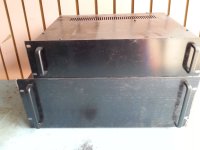
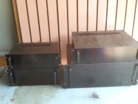
So I had a look at older and cheap mixers on e-bay.

I found that these 
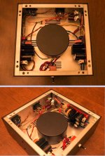
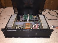
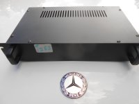
Kawai (MX-8SR) mixers had plenty of room inside. Plus they were all built with "through-hole" components and single-sided (non-plated through hole), making the part swapping easy.
I was able to buy the schematic online. Not easy to find !! (contact me, I have it scanned)

What I did NOT change, was any switches, pots, and connectors. I also left the "peak meters" alone. The point of this, was to have all the hardware in-place....a real time-saver !!!

I left most of the film resistors alone, except around the balancing output circuit, where I swapped in some precision 10k Vishay's (RNC90y).


Swapped parts (briefly):
All opamps. 4558dd .....to mostly LM4562 (no sockets !).
Disc ceramics....to film types (except for power-supply bypassing).
DC blocking aluminum caps.....to (lower value) film type.
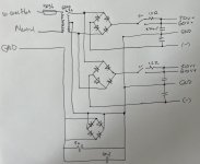
+12.6v PSU.....to new 317/337 @ voltages of my choice, and a new power transformer.
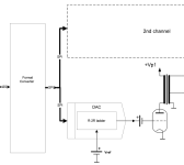
Headphone circuit removed.....replaced with my own (based on Jung composite line driver, AD823/AD815ay)

Notes:

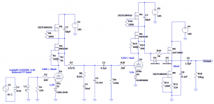
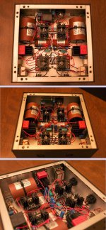
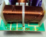
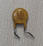
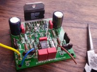
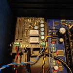
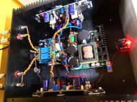
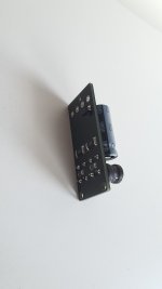
The LM4562 is a "fast" opamp. To prevent stability problems (like oscillation) I added 0.1uf ceramic bypass caps directly to the power-supply pins(4&8) of each opamp, to ground, and another 0.1uf cap directly from pin 4-to-8.......all on the underside of the board. (see pic 2)
There were NO bypass caps there, previously.
I also did NOT use sockets....the new opamps were soldered in place.
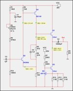
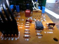
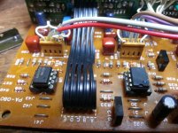
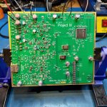
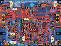
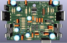
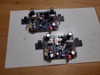
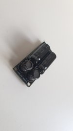
Feedback loop compensation caps used to be ceramic, now they are mica types. Where there were no compensation caps, I "piggy-backed" some 12pf caps, soldered right on top of the feedback resistor (bridging it), just to ensure stability. (I did not calculate this value, I guessed 😱 ) (see pic 1)
Preliminary testing....no oscillation ! (I was worried) The new opamps run barely warm to-the-touch.

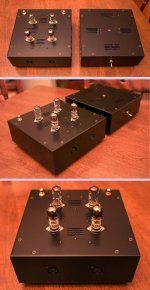
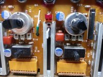
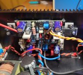
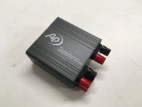
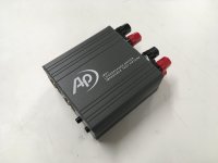
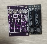
Since there are 8 stereo inputs, I reserved lines 7 & 8 for "opamp swapping", where I did add opamp sockets. This is just for curiosity and testing. Right now, one line has NE5532's, and the other OPA2107's. Will I be able to hear a difference ? Time will tell. (see pic 4)

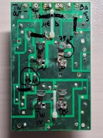
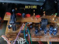
Mixers like this are chock-full of DC blocking caps at the opamp inputs, because a variety of outside signals are fed into the unit which may be passing along unknown DC....making such caps nearly necessary. (see pic 7 "before")
All those caps were previously electrolytics, so those were replaced by film types.
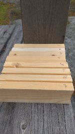
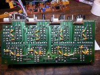
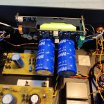
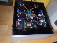
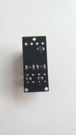
There were a few places that still needed electrolytics.....and I didn't wildly replace ALL of them. The electrolytics left in the circuit were swapped out for newer versions. (I even tried some polymer 'lytics) (see pic 3)

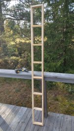
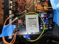
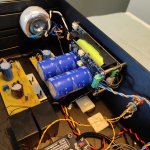
The original headphone circuit seemed weak, as it employed just one 5216p dual opamp, for stereo. I'm adding a separate headphone board I "designed" (actually, Jung did, I copied it for my private use, I made a few adjustments)....that fits quite easily inside. (see pic 5)

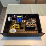
The original PSU circuit fed the entire unit with +12.6v.
I am able to raise this to suit the opamps with my new PSU, but I need to think about....if the metering circuits can handle up to +15.5v (??). The output level meter already has trimmer pots for level adjustment.
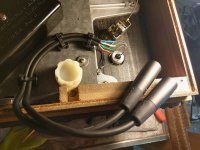
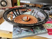
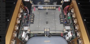
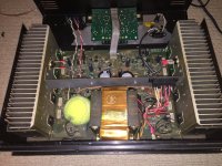
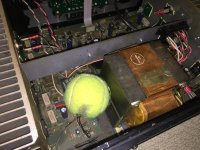
A (shielded) transformer was replaced accordingly, to suit higher voltages if desired. (see pic 6)

You gotta love the older pc boards.....big holes that when using a wick and a decent iron, de-solder so easily !
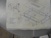
Luckily, the schematic was accurate, except for a couple of errors.....and the boards were clearly marked.

Attachments

  • 20150603_234116.jpg
    20150603_234116.jpg
    121.8 KB · Views: 498
  • 20150603_234048.jpg
    20150603_234048.jpg
    212.3 KB · Views: 491
  • 20150603_234151.jpg
    20150603_234151.jpg
    184.5 KB · Views: 493
  • 20150603_234128.jpg
    20150603_234128.jpg
    164.1 KB · Views: 465
  • 20150605_144013.jpg
    20150605_144013.jpg
    156.5 KB · Views: 482
  • 20150605_145143.jpg
    20150605_145143.jpg
    158.9 KB · Views: 385
  • 20150326_152911.jpg
    20150326_152911.jpg
    172.6 KB · Views: 393

Project IV: USB sound card with Hi-End twist

Hi folks,

For decades I’ve been dreaming of making digital audio system which would sounds indistinguishable from a good quality analogue one (based on tape or vinyl media).

But only recently it became feasible to build such a system for the reasonable amount of money, thanks to the new AD and DA converters (and other supporting chips) on the market.

Long story short – here is my first humble attempt, I called it Project IV.

Generally, it’s a two-channel AD-DA converter (ADAC) built with high-end philosophy in mind and utilising industrial-grade ADC and DAC chips with good metrological parameters.
The ADAC board itself has balanced inputs, balanced and unbalanced outputs and supports 44.1, 48, 88.2, 96, 176.4, 192, 352.8 and 384kHz sampling rates.

Special steps were taken to reduce system jitter, including low phase noise Crystek 957 series oscillators and 13 low-noise linear LDO regulators on boar, mostly LT3042.

XMOS based DIYHK board is used as USB to I2S interface. Xilinx CPLD converts I2S signals to SPI interface, needed for multibit DAC, and forms sampling logic signals for SAR ADC chips (LTC2380-24).

While looking for information and app notes on LTC2380-24, I have come across very interesting project of Frex: https://www.diyaudio.com/community/threads/osva-open-source-versatile-analyzer.335005/
Highly recommend that thread for those thinking to use LTC2380-24 in their projects.

In my case ADC converter is always working at 1.536MHz for 48k band (or 1.412MHz for 44.1 band) sampling frequency. For 384k, 192k, 96k or 48k output LTC2380-24 chip does 4, 8, 16 or 32 averages respectively, thus improving S/N ratio. The same happens if 44.1k band is selected.


For DAC section I have selected 20-bit AD5791 (or 18-bit AD5781) chips. The reason is that since 2003 I love to use the following topology in my DACs:


DAC topology_small.png


It allows me to built a DAC with no feedback in any part of sound path, including reference and output buffer. Decades of intensive use has proven very good musical characteristics of this topology. And AD5781/91 chips have unbuffered R-2R matrix with no OP amp on the output.
Nevertheless, current PCB is allowing to use traditional schematic with high-quality OP amp buffers.

Overall view of the finished board is shown below:


ProjectIV top PCB_small.jpg


ProjectIV bottom PCB_small.jpg


I have done some preliminary measurements of ADC section using low-distortion generator from (again!) Frex (https://www.diyaudio.com/community/...-10khz-oscillator-new-updated-version.287892/).

Found them quite satisfactory:


THD_-0.1dB.png

Noise.png


The next step now is to built tube buffers for ADC and DAC, so the work is in progress…

Attachments

  • DAC topology_small.png
    DAC topology_small.png
    8.6 KB · Views: 170
  • ProjectIV top PCB_small.jpg
    ProjectIV top PCB_small.jpg
    391.2 KB · Views: 171
  • ProjectIV bottom PCB_small.jpg
    ProjectIV bottom PCB_small.jpg
    305.4 KB · Views: 172

Simulation of Complex Rooms

As I design my retirement cottage, I would like to simulate the acoustics and correct any mistakes in design prior to construction.
Unfortunately, the simulation tools I have found assume "normal" construction and cannot replicate my plans. Hopefully someone can direct me to more sophisticated tools...
The listening room:
-The cottage will on a bluff above a scenic river so the exterior walls will be largely glass to enjoy the view.
- To address standing waves my idea is for the exterior walls to be inclined outwards, like an inverted pyramid, with approximately 30 degrees of inclination.
---This should eliminate standing waves between parallel walls, as they are not parallel
---Any standing waves must involve the ceiling, and the ceiling joists will be exposed as sound traps and provided with damping material
Are there software tools which can simulate such a room?
Are there precedents which have been empirically evaluated?
  • Like
Reactions: Pano

6 Transistor Amp with EXICON Laterals Class AB 10 Watt

A little amp with 10 Watt in Class AB with EXICON Laterals.
The power supply should be like 30-34 Volt DC.
So, a suitable transfomer can be 24VAC or 2x12VAC.

Simulation gives an output of 11.4 Watt with 33 VDC supply.
The distortion is rather low for such a basic amplifier. SPICE specify it as THD 0.0001%.
Bias of the MOSFETs is 200mA.
The amplifier is Two Pole Compensated, TPC.

6T Poweramp EXICON_06 TPC.jpg

Suggested affordable quiet amp for high efficiency speakers

Hi everyone,
If you have seen my post history you might know that I have had a pair of Audio Nirvana 15"s in boxes for years.

Recently however I had the idea of possibly using them at my work on my desk in an open baffle config.

I hooked up my basic Accento 2x20W (https://www.theloudspeakerkit.com/ada40-accento-dynamica-40w-amplifier) to them yesterday to see if they still worked, and thankfully they do, however there was a bit of noise coming out of the speakers when the amp was turned on.

My understanding is this was happening because the speakers are 96db efficient and will therefore pick up any noise from the amplifier and make it audible.

So I had a look on AliExpress for possible low power amps to replace the amp with and was dazzled at the seemingly limitless number of amps for sale there.

I thought it would be a good idea to ask here instead as many here have so much more experience than me in this area - does anyone have any amp they can recommend to me, even if it maxes out at 10w, that is quiet enough to not have audible noisy output from my speakers when idling?
I'm hoping not to spend more than ~$70US or so including power supply.

Thanks for anyone's input in advance.

Usher R1.5 DC offset and Bias adjustment

First off not an engineer, but I have adjusted bias of a couple of vintage amps with the help of a service manual that pretty much tells me where to stick my probes on the amp.

I do not have a service manual of my amp and emails to Usher has not yielded any results.

I know where the bias trimpots are, it is the blue trim pots on the left and right board. So if anyone can tell me where to exactly stick the negative and positive probe on my multimeter on the board, then that would be great.

Since there is only 1 set of trimpots, how is DC offset adjusted ?


Thanks

Attachments

  • usher r1.5 internals.jpg
    usher r1.5 internals.jpg
    82.3 KB · Views: 284

Mark Levinson 33H

Hi friends
I am trying to understand something
I have looked over the schematic of the mark levinson 33H the base resistors consists of thick film (matal glaze) TF-20 resistors rated at 1W
What was the thinking of the designer since when it comes to resistor noise thick film are worse than thin film and off course wirewound resistor.
The only thing that film resistors are superior are rise time and higher bandwidth.
But since we have Ayrton-Perry wirewound wich has high bandwidth and rise time close to film resistors...
Still why the use of thick film instead of wirewound? since the 33H should be statement amplifier cost no object.
Do anyone use vishay mills or other Ayrton-Perry resistor in the signal path and can give me his opinion???

God bless you all

Nehoray

Attachments

why are horn sensitivities so high? why don't they make the impedance higher?

OK yes horn loading increases the efficiency, and so on. But generally we end up with horns whose sensitivity, especially as they are much more directional, is WAY above even pro woofers.* Thus (the relatively small percentage or so I believe of active crossovers aside) we wastefully end up padding down with resistors.
--> why don't the manufacturers make the horn drivers 16Ω or even higher more often?
Yes, some horns are drooping at higher frequencies, but even so are pretty hot.
???

*this thread was kicked off after reading this review in particular
https://audioxpress.com/article/voi...tal-pro-s-10hx230-coaxial-10-pro-sound-driver
but the "ailment" is a common one.

For Sale DDDAC PCM1794 NOS 4 boards transformer output

Hi all,

I am thinking of selling my DDDAC PCM1794 NOS DAC.

Link to official thread
https://www.diyaudio.com/community/...with-the-pcm1794-and-waveio-usb-input.224108/

It is fully functional but I am considering taking an another route in my soundsystem and making a turntable my primary source, so I am looking to scale down a little bit.

A few words about the build:
  • 4 deck version
  • blue mainboard
  • Audio Note Niobium Non-magnetics I/V resistors
  • Tamura output transformers (EXTRA GREAT studio quality)
  • Amanero USB input + BridgePi + FifoPi Q7 + Accusilicon clocks (90 & 98MHz)
  • DDDAC U.Fl modules to connect to FiFoPi Q7
  • IAN CANADA LIFEPO4 MINI Battery Power Supply Module 3.3V + IAN CANADA UCCONDITIONER MKII Ultra Capacitor Conditioner Board 3.3V with Maxwell 325F supercaps for FifoPI Q7 clean side
  • 2x Salas SSLV1.3 UltraBiB shunt regulator to power everything else (5V and 12V)
  • 2x toroidal transformers
  • https://modushop.biz/site/ Enclosure

It plays 384kHz sample files with no problems. Sound is just marvelous, the best DAC I ever owned!

I spent about 2500€ for this build, so I am taking only serious offers. For a very interested buyer I can include a Mac Mini Late 2012 with external linear power supply in the price so this is then a real ultimate perfomer ...

Location: Croatia, Europe

Thanks,
Tomislav

Attachments

  • 429811953_10161111722624297_4391329468247138335_n.jpg
    429811953_10161111722624297_4391329468247138335_n.jpg
    382.4 KB · Views: 420
  • 429811455_10161111722574297_1312028033316920266_n.jpg
    429811455_10161111722574297_1312028033316920266_n.jpg
    472.6 KB · Views: 412
  • 429847016_10161111722599297_4977264618664896500_n.jpg
    429847016_10161111722599297_4977264618664896500_n.jpg
    486 KB · Views: 353
  • 429868876_10161111722534297_1595463143887304213_n.jpg
    429868876_10161111722534297_1595463143887304213_n.jpg
    417.3 KB · Views: 385

Spherical sound?

Been a while. Got email about a cool spherical design. Keep one experimenting. Mistakes turn into success. Love the participate who used a styrofoam ball covered with fiberglass. Also love the beafy Vifa 10 . Awesome basket. Love their tweeters. Especially the ring radiator 25 ? Used Tang Bang small full range and in the right enclosure sound good. I built a small Voigt design and it makes mediocre speakers sound good. Look cool too.

Which diyAudio designs are available on Aliexpress etc?

Hi all

There is some great contributions with open source designs and gerbers on diyAudio. The hardest part is deciding which one to build 🙂.

I think some of these have made their way to Aliexpress sellers. Sometime ago I came across the Ultimate Fidelity 100w amp on AE which appeared to be one of the revisions from the thread here.

Does anyone know of any boards/kits/amps from AE based of designs from here?

Blame ES/ST reloaded

Hi,
i have read in the (chaos) threads about the Blame Amp a year ago. I was interested in the Blame ST Amp and wanted to build this Amp. I made some pcb's with KiCad and in the last days i build the Blame ST. With my pcb you can also build the Blame ES, components are marked on the pcb. For the known problem with one BC546 (Q6) you can put in a 1K resistor and a diode BAV21 when building an ES Amp.

The pcb is similar to the XRK FH9 and many others, transistors on the pcb side and bias transistor underneath the pcb. The old pcb's, shown in the original thread, were rather large,
now the size is 99 mm x 74mm. For heat release on the heatsink this version is better i thought , but the amp needs not much cooling. The biasadjusting is very stable from power on. After 2 hours not much heat on the heatsinks. If i had known i had choose a smaller housing.

My Blame Amp is powerd by an 500 Watt Connex SMPS, +- 35 Volt, the bias is set to 70 mA. The amp sounds very good, doing everything right. I use the toshiba 2SC5200/2SA1943.
Perhaps i give some MJE transistors a chance later.
If someone is interested he can get the gerberfiles over PM. Dont know if it is good to post here, or do you see no problem with that ? The original thread is 10 years old.
Perhaps Carlos, Destroyer X, had been happy to hear from a Blame Amp build in Germany...but he died month ago...RIP.
A homage to Carlos building his Amp...

Peter

Attachments

  • Bla.jpg
    Bla.jpg
    752.3 KB · Views: 133
  • Bla2.jpg
    Bla2.jpg
    412.2 KB · Views: 139
  • bla3.jpg
    bla3.jpg
    450.9 KB · Views: 134
  • bla4.jpg
    bla4.jpg
    408 KB · Views: 129
  • bla5.jpg
    bla5.jpg
    429.4 KB · Views: 129
  • bla6.jpg
    bla6.jpg
    321.2 KB · Views: 132

For Sale Audio Precision IMP1 Loudspeaker Driver Impedance Test Fixture

Greetings :wave:

For sale I have an Audio Precision IMP1 Loudspeaker Driver Impedance Test Fixture. I acquired this through a previous employment, of which I currently do not have an AP system. Therefore, I have no use for it. It is brand new, never used.

Selling for $50 shipped in the U.S.

PM if interested. Thanks 👍

Attachments

  • IMG_0488.JPG
    IMG_0488.JPG
    263.4 KB · Views: 128
  • IMG_0489.JPG
    IMG_0489.JPG
    222 KB · Views: 93
  • IMG_0490.JPG
    IMG_0490.JPG
    297.1 KB · Views: 118
  • IMG_0491.JPG
    IMG_0491.JPG
    202.9 KB · Views: 133
  • IMG_0492.JPG
    IMG_0492.JPG
    225.2 KB · Views: 115
  • IMG_0493.JPG
    IMG_0493.JPG
    279.3 KB · Views: 126
  • IMG_0494.JPG
    IMG_0494.JPG
    259.2 KB · Views: 145

*non* polarized film caps?

So i've noticed that on one of the protoboard iterations of the preamp ive been tinkering with, (one of the versions of it before i moved to a breadboard anyway, has big 250v 1uf input capacitors on it.) that if i waved my hand over the input cap on the left channel, that the left channel would hum while my hands was close to it. Thought it was the tube at first but just realized while messing with it, its that input cap.

The right channel did not do the same thing, but i DID notice that on the left channel, the input cap was wired in the opposite direction. Could tell by the printing on the cap. I flipped the cap around on the left channel, and now it doesnt hum when i get close anymore, only if i firmly grasp the cap directly or touch its leads.

I was under the impression that with on a non polarized film cap polarity doesn't matter, but i just experienced something to the contrary. It sounds the same but seems to create a path for noise to more easily enter the amplifier oriented one way over the other or something.

I reversed the right channel cap trying to learn something, and its doing the same hum thing now too, My cheap axial yellow chinese polypro caps do this too. None of my box style or safety caps do this though (all radial). Noise with box caps seems to be the same oriented either way, whether i touch them or not.

Why is this a thing thats happening if it doesn't matter which way you orient a non polarized cap? (obviously theres a reason, but i have no clue what it woud be))

Intro

Hello everyone, glad to join.

I'm interested in next, Do you have a preference between Qobuz vs. Tidal and if so, why? My experience with Qobuz customer service has been exceedingly poor. Can anyone attest to whether Tidal's customer service is any better? Additionally, how does the selection compare between the two platforms?
Thank you!

Buying thin (aluminized) Mylar in Europe?

Hey everyone.

I'm slowly but surely getting into the hobby of making planar drivers. I've done research and I'm confident enough I can have a go at building my first driver. For the time being, I want to stick with building a planar headphone driver, Hifiman style. Having found teardown pictures online, their driver look sort of... amareutishly put together, even in their high end expensive pairs. Here's a picture of the Ananda's driver (500$)

eDqCZwfTrB.png


Or the HE-6 (1200$) which employs a thicker membrane that is gold-plated.

MheEBxlevC.png


Or the HE1000SE (2250$), which uses rather thick traces.

auEnrgVMZ1.png


I want to play around with thin, pre-aluminized Mylar preferably, to etch out the traces on the membrane using ferric chloride by masking them out with stencils.

My only issue is, I cannot seem to find any way to source the materials here in Europe.

Does anyone have any idea where I could get my hands on 1 to 10μm, preferably aluminized mylar, in reasonably small quantities?

Perhaps a fellow DIYer out there is sitting on a large stock and would be willing to part with a tiny bit of it, just so I can start playing around?

Altec pro amp, for home use ?

I found a nice altec lansing 9442a anniversary edition, for around $150, those amps were designed for the pro market.
I am going to use for home audio

Can you guys comment on the design and specs ?

I noticed 2 UPC4574 op amps
and 2 10000ug 63v power capacitors
transistors 2SA1302 / 2SC3281

The brochure give spec for TIM noise, less than 0.1

Attachments

Picking a woofer for 2-way Synergy build?

So, now that my first fullrange build is well under way, I've been browsing the forum as a mean to keep furthering my newly found speaker building abilities. I ended up reading all I could find about synergy horns, taking pages upon pages of notes, and decided and I wanted to have a go at it once my first speakers will be up and running. Because what's better than immediately thinking about another build while the current one is still in the ropes?

After seeing @xrk971 and @bushmeister's amazing build, I figured some pretty insane things could be achieve with a regular 2-way horn with two woofers per side coupled with a FR driver, XO'd at 500/600Hz. But it's when I saw the insanely low-distorsion low-end extension bushmeister was able to achieve that I figured I absolutely needed to build one myself.

My goal for this project is therefore to end up with a highly efficient, very low-distorsion point-source speaker that can achieve great, clean low-end extension. They'll be used at nearfield volume (never quite exceeding 60/65dB) and listened to at no more than 1/1.5 meters. I figured this would allow me to really make use of the very high efficiency, betting on very low need for displacement, and therefore vanishingly low distorsion levels.

I set out to look for a good woofer driver to use, basing myself on the guidelines I had gleaned after reading what felt like thousand of forum pages. I wanted something that would allow me to reach close to 30Hz and possibly below, at reasonable levels. Here were my pre-requisites.

  • Preferably 8"
  • Large excursion capability for low HD
  • Low-ish Qts to optimize horn loading
  • As small Vas as possible
  • Strong motor to further reduce excursion
  • Highest possible volume displacement (Vd)
  • High BL preferred
  • 8Ohm so they can be wired in parallel to achieve a 4Ohm load

I made a quick Excel sheet to input different drivers' parameters, trying to stay below 150€, because I'll be buying 4 of these. I calculated an idealized version of electromechanical damping to get an idea of the motors' strength by doing (BL*BL)/Re. I know this doesn't account for losses, but it still gives a workable number. I also calculated an idealized version of Vd by doing Sd*Xmax.

explorer_IfFQrrUAOA.png


Here are the results. The grey line is the driver bushmeister used. I used it as a reference since he stated the TS parameters were seemingly perfect, and also because I saw the measurements of his finished speaker, and that sweet, distorsion-less extension into sub-30Hz...

The clear winner based on my research is the SBAcoustics SB20PFC30. It is not only the cheapest of them all, but it also has:

  • High Xmax of 7.32mm (measured by third-party, not by manufacturer)
  • Highest efficiency of the bunch at 90.5, giving me about 93.5db when wired in parallel. Would allow for 'easy-ish' matching with a very efficient horn loaded FR.
  • Highest volume displacement of them all
  • Good BL / Motor strength
  • Reasonable Vas. I can live with giving each horn 60 to 100L to breath. I intend on running them sealed to get the cleanest bass transient possible.

explorer_IWxNHp32Gw.png


The only thing keeping me from immediately pulling the trigger is this: am I missing something? What's the catch? The driver will have to deal with everything below 500/600Hz.

It models really well. I even tried a tapped horn sub, and I get a very respectacle extension down to 27Hz at about 90/91dB before it rolls off. Usable all the way to 100Hz.

explorer_WTob8XhUFi.png


So I'm calling upon the Synergy boys to help me figure out if I'm making a sane decision. I've been itching to pull the trigger.

Attachments

  • explorer_IfFQrrUAOA.png
    explorer_IfFQrrUAOA.png
    33.8 KB · Views: 83

Yamaha NS1000m active upgrade, advice nedeed

Hi everyone,

I am going with active ns1000m rebuild speakers with minidsp flex eight and 3 amps AB class by primare.
In the software of minidsp i have tried factory values 500-6000Hz but system sounds bright and not balanced. I got advice that i need to do a -3 db on both tweeter and midrange. Is there anyone who can help me with crossover settings for all speakers?

For Sale Electro Harmonix 300B pair

SOLD
A pair of EH 300B , matched pair bought years ago and only lightly used for testing and evaluation of an amp.
They were made to operate in an amp that is well within the recommended specifications of the tubes.
I would reckon an approximate of 500-600 hours of usage and they are still going strong.

155USD shipped to you.
Will be packed very well.
Paypal Friends & Family only please.

Semi SMD inline SMPS filter

Hi. I made a new topic about my version of Mark's p089zb filter, as per his request so i can provide support for this version.

I went the smd route for several reasons. First one is constant reduction of trough hole component stock/manufacturing, in this case current sense resistor needed for marks original design. Smd version is plentiful and can be found below. Another reason is, while the original design is small, you can always benefit from smaller footprint. And third one is that i am one of those ocd guys that like to have components looking as perfect as they can be, and this one hits that spot for me personally, compact, all traces are same width, almost the same length, while at the original i had the beef with, due to layout it had to be narrower at two points, and tracks are uneven length and unnecessary long (i don't think it matters much for circuit design, but i like things as tidy as possible).

I have kept two components trough hole, inductor and capacitors as those are usually still plenty available, and i'm nowhere near Mark's knowledge to do complex calculations that he has done to go smd inductor route. And those two components are critical. The rest are 1 to 1 replacements, and i chose them to be as big footprint as possible for manual soldering (i haven't used my hotplate for this to make sure it is easy to hand solder). Diode is direct replacement from the same manufacturer, only in smd package. Smallest component is in 1206 package which is a plenty large footprint smd component.

Component list (mouser):

71-WSL2512R0400FEA current sense resistor 0.04R 2512 smd package 71-CRCW1206953RFKEAC 953R resistor 1206 smd 576-TPSMB68A tvs diode DO-214AA-2 smd package 647-UHW1H471MPD 470uf 50v capacitor LS5mm D10mm TH (these are recomended, but can be replaced with any low esr capacitor that fits the footprint and values) 652-RLB0912-2R2ML 2.2uH 7.5A 0.10R inductor,LS 5mm and Diam 9mm

I have trialed it in my b1k nutube preamp, works as nice as the original design. In attachment are mounting hole version and smaller one without mounting holes if someone needs even less of a footprint. Mounting hole version i have increased to 2mm more in length so larger head screw can be used. You can see the size comparison as well.

Attachments

Projects by fanatics, for fanatics
Get answers and advice for everyone wanting to learn the art of audio.
Join the Community
507,663
Members
7,883,181
Messages

Filter

Forum Statistics

Threads
405,981
Messages
7,883,181
Members
507,663
Latest member
The driver