Adcom Preamp Chip needed

Hello,
I'm a newbie here and am happy to be aboard. A friend of mine is helping me restore some vintage stereo equipment I recently acquired.
I have been searching for a chip for my Adcom Model GFP-565 Preamp.
Please see the attached image. It may be that the chip was made by someone else.
Any info you have would be most appreciated.
Thank you,

Matt

Attachments

Show Off Your Audiophile Tribble

Wilfredo my Chilean miniature blue sat on the BigBottle phono stage waiting for a listening session to start. He much prefers it to the Naim, Muffsey and Schiit stages I had before. Clarity at the top and mid with bass that's there when it's supposed to be he says.

20240409_105223.jpg


Wilfredo sat on the Heybrook TT2 preparing for his daily exercise. So far at least he's comfortable at 33, though hopes to be able to do shorter sessions at 45 later this year. He says the suspended chassis is excellent for longer distances and prefers the Heybrook to my Hydraulic reference because he hates having to continually jump over the 'gold blobs'.

20240409_105257.jpg


His favourite music is ambient, particularly Eno's "Music for..." series and, interestingly, Zeit period Tangerine Dream. It's fun to watch him trying to dance to Bowie's "Lets Dance" though...

🙂

Fender Frontman 212R distorting even on clean channel.

This amp recently began to sound like dirty distortion no matter the channel, at moments almost to a muffled/drowned out sound. I first swept through all of the pots hoping to find a dirty one causing the issue, but none changed the conditions of the distorted tone. I checked and cleaned both inputs for connection issues, no change. Plugged the Pre-Out to another amp and got the clean tone the amp had since it was new. Then plugged the speakers into another amp to see if the speakers were blown, but again got a clean and clear tone. I pulled down the circuit board to see if any capacitors were swelled or leaking, or if I saw something burned or broken visually, but all looked good from the top end (haven't yet pulled it completely out to see the bottom of the board). Does anyone know of a common issue/repair worth trying, or advise in next step diagnosing of this issue?

I have experience in circuit board soldering, DMM, schematic of this board, and have been an ASE certified electrical diagnostic specialist for many years. I may be new to circuit board component testing but I can follow directions with the best of them. Any help I can get with this would be great.

Fostex FE206NV2 Backloaded horn assembly

Hi. I plan to make FE206NV2 backloaded horn. The specification sheet gives a blueprint for it. I already ordered 18mm plywood with cutting to dimensions. My questions is how to assemble it?

I am not a professional carpenter, but I have some experience. I made several cabinets however I used screws in assembly. In this project I want to use only glue (Titebond).

So is it ok to make it without screws?

In what order do you suggest I should asseble?

I also want to protect it with varnish so moisture will not influence the plywood. How to apply this varnish inside?

Any advices are welcomed. 🙂


PS. I have different types of clamps (I haven't bought 1200mm ones yet, but they are in process) and also bought a pair of clamps for a corner.


horn.png

20240409_141316.jpg
20240409_141256.jpg

Attachments

1998 Marantz CC48 5-CD changer does not spin up spindle after laser focus attempt, resulting in nodiSc

My CC48 has run quite well for almost 24 years. I have successfully replaced the CDM12/VAM1201 transport twice over this period. The latest transport is ~7 years old.

(Slightly off-topic: In 2022, the gear-pulley combo that moves the tray in and out broke some teeth. A few months later, its twin gear-pulley that rotates the carousel seized up. I had no time then to fix these, so the unit remained unused for over a year. Recently I 3d-printed these gear-pulleys as a trial, meaning to CNC them later. The 3d prints work quite well — tray ejects and retracts, carousel rotates. However...)

When I insert a CD and play, the laser detector is duly blocked as the CD passes the transport, and so it does detect and register a CD in the correct slot.
It rotates the carousel to position the (only) CD present into the VAM transport, which duly locks and rises. The laser lens moves up and down, and then it just ignores the CD and moves on. The spindle (turntable) motor never spins up. The laser diode is nominally working, I can see the red glow. After a few carousel moves, I get "insert disc" or "nodiSc" on the front panel.

Switching to test mode, I can successfully spin the turntable motor, move the focus servo up and down, move the sledge in and out, and even conduct the radial test (although I do not understand what that does). No error message is printed.

Power supply voltage readings are all normal (+10V a little lower than -10V in magnitude). Both flex cables continuity check out ok. I have access to the service manual. Test point voltages that need only a multimeter check out ok. Spindle motor resistance and voltage look normal. I don't have access to an oscilloscope yet, will soon organize one, but, without the spindle spinning up, don't know what to check. HF eye pattern won't happen until spin-up, will it?

I tried replacing the VAM1201 (full mechanism, not just the laser) with another (used) one of questionable origin. Same problem. I don't have access to a working new VAM1201 but I can order an unbranded knock-off from ebay. (The last one that was working fine for many years was a knock-off from ebay, anyway.)

I am looking for advice on whether spending ~13 USD on a knock-off VAM1201 is worth it, or should I suspect something else. (In particular, might the 3d prints be deficient in some way that is not obvious. Or, what could I have damaged during the manipulations needed to replace those gear-pulleys.)

I can post further info as needed. Many thanks for any advice in this matter.

1997 Bose 301 Series IV no more tweeters diagnose help

Hello,

i'm totaly novice here and trying to diagnose these which have no tweeter sound and woofer seems very low sound to me
when i connect the tweeters directly, rear oriented one (3") give good cristal clear sound but the front oriented one (2") nothing at all.
servicing manual inserted

thanks

IMG_20240407_205536.jpgIMG_20240407_205545.jpgIMG_20240407_205649.jpgIMG_20240407_205736.jpgIMG_20240407_205748.jpgIMG_20240407_205658.jpg

Attachments

Kicker ZX750.1 overcurrent problem

Hello diyaudio family

In my examination, there is no problem with the supply MOSFETs and output MOSFETs. The output driver transistors are solid.
The problem with my device is that when I disconnect the lm361n, the power led turns from green to red and repeats this over and over.

But when the lm361n is plugged in, the power LED is fixed in green and the relay does not turn on and the device draws excessive current and the supply mosfets start to heat up.
When 7912 and 7812 are removed, the relay opens.
I suspect LM361n, can you help me where else should I look?

Marantz PM5000 DC offset voltage > protect mode

Hello,

discovering i registered in 2013 but never participated at this community, sorry .
As i'm actually trying to repair an amplifier (with kind help of Audio Service member👍 )
i decided exposing here my learning path... may it serve to others and help me succeding at same time...

At switch ON, power red led lights, after 1second relay clicks, 3 blue leds speakers A & B & loudness & red led MUTE goes ON then mute red led goes OFF,
then relay unclick, 3 blue leds go off, power red led flash undefinately > protection mode.
on 14pins main bord connector protect_1 and _2 signals go to 4,97V

Mesurement power supplies ok, bias to be adjusted later and a BIG DC offset problem Right chanel:
KIA 7805A: IN 24,3V OUT 5,02V
KIA 7812: IN 24,3V OUT 12,05V
KIA 7815A: IN 24,3V OUT 15,08V
KIA 7915PI: IN 24,3V OUT -15,05V
Bias Right: 23mV Bias Left : 32mV
DC Voltage: -2,3Vdc on pin 1-2 Left-CH bias connector to GND and +0,2V on pin 1-2 of Right-CH bias connector to GND

Attachments

Output transformer max primary current

I have a few tube push pull output transformers with limited information available and I would like to determine what output tubes they could be used with.

I can measure and calculate the turns ratio but I don't understand how to figure out the maximum primary current rating, this would tell me which tube type I can use and how to bias the output stage without risking damage to the transformer.

For example I have a 7:1 transformer (30K:600) and the datasheet only specifies a maximum level +23dBm
I have measured dc resistance 720 ohm on each primary side.

I have been trying to figure out a way to calculate the primary dc current rating and this is what I came up with :

+23dBm = 10.94V (from online calculator)

10.94V * 7 = 76.58V on primary side

76.58V / 2 = 38.29V on each primary

38.29V / 720 ohm = 53mA on each primary


I am not sure at all about this calculation, and what if the dBm rating was not specified in the datasheet ? That would further complicate things.

My Leak-enstein Stereo 60

Historical Background

Spoiler alert: strong heresy inside – Collectors please bail out NOW!

I know the Leak brand by reputation, and it has a 
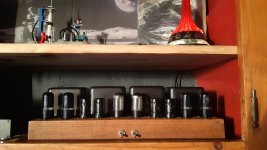
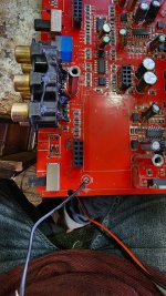
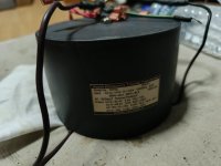
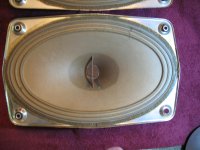
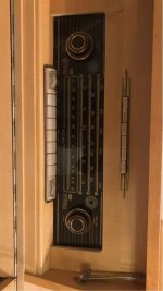
very strong following, even today. I had the opportunity to buy this Leak ST60 at the local flea market in the 80’s. I don’t remember what I paid, but it wasn’t exorbitant like it is nowadays.

I cleaned it up, re-tubed, replaced most capacitors, had a listen, and was disappointed: the sound was anemic, devoid of finer details, your typical “warm and fuzzy” sound of vintage gear. Maybe a tiny bit better than the old Quad II, but barely so.

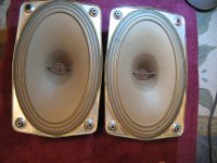
It went on a long-term loan to a friend’s who didn’t like it either; it came back dead after a few months and spent many a year in a closet.
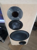
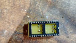
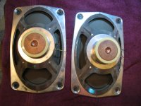
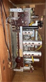
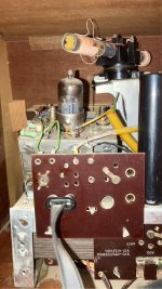
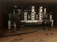
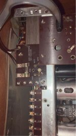
01-ST60-Tag.jpg

02-Stereo60.jpg

As-Is

The topology is loosely based on the Mullard circuit. Possibly to meet the high gain requirement of yesteryear, they used a 12AX7/ECC83 for the phase inverter, running at only about 0.8mA per leg. A most unfortunate design choice, shared only by Jadis AFAIK (and Mullard, but Mullard didn’t sell amps for a living).

Also questionable is the UL tap at 25%: this lets them extract a bit more power, at the expense of a more pentode-like behavior.

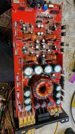
On top of questionable engineering decisions, I also have the feeling it was a company run by bean counters: the 
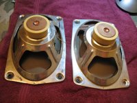
output transformer 5 layers S/P/S/P/S, like a Dynaco, OK for mid-Fi.

04-Leak ST60 OPT.jpg


But IMHO, 7 layers is the more “natural” configuration for ultra-linear, as illustrated here:

04-7 layser OPT.jpg


Some of the upper-tier winders use 9 layers, and P. J. Walker (RIP), a direct competitor, went as far as 13 layers in the Quad II (I just love PJ's go for broke approach)!

As a side note, here’s my plea to all commercial winders: please publish at least:
  • The frequency response graph to min. 200KHz
  • All inductances
  • All capacitances
  • If possible, distortion vs frequency graph
If you don’t, I’ll assume you don’t know what you’re talking about, and I’ll call the next guy in line. FYI, Partridge did nearly this, almost a century ago!

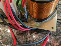
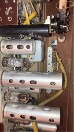
Back to the ST60: another thing I don’t like is the 0.3H choke: this is the smallest one I’ve seen in any amp, decent or otherwise! Just enough to get away with it, right, guys? Me, I’m not even sure it’s enough to protect the GZ34 before it from the brutality of the 360uF reservoir caps I use.

So, the philosophical question: what justifies the cult-like following of this brand?

Measurements, then

At the time of purchase, the THD, the Holy Grail according to Leak’s selling pitch, is kind of OK, at about 0.2% at 1kc/s. The biggest surprise is the open loop bandwidth: a whopping 3kc/s (you read right: three thousand cycles per second), worthy of an IC opamp!!!

The gear I used at that time was the very temperamental Radford DMS 3 (<0.002% THD).

03-Leak ST-60 FR+THD s.jpg


Also, the power vs load is narrower than that of an ARC D70. This is surprising because the D70 is almost a true tetrode design with only a small amount of cathode feedback, while the ST60 is ultra-linear, but only at 25%.

04-Leak ST60 load S.jpg


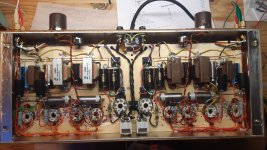
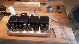
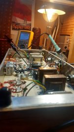
Some 40 years after the fact, I decided to take it out of the closet and see if I could make it better, without doing anything drastic like drilling holes or otherwise butchering the chassis.


The objectives

My priorities are:
  • De-opamp (not a verb) by moving the dominant pole to 10KHz or more.
  • De-starve (not a verb) the low-level stages.
  • Reduce the overall gain and the loop gain.
  • Nice to have: add a triode pentode switch.
Note that all of the above go nicely together.
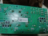

The mods

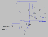
First thing first: the ECC83 in the phase inverter must go: what I have in mind is the superb E80CC. Because they don’t come easy, my plan B is the 12BH7: they are electrically similar enough to be considered drop-in replacements. A bit over 3mA per leg should do nicely, and a tail of 18K lets me direct couple the phase inverter to the input tube, saving a low frequency pole. A small trim pot is added to a plate resistor to balance the amp.

The input ECC83 will have to go too: nothing wrong with it, just too much gain. The ECC81/12AT7 I picked is a questionable choice, I know: it’s the least linear of the popular ECC81/2/3 trio. We’ll see.

The purpose of these mods is to fulfill prio #2 above, which fulfills prio #1.

High bandwidth, low feedback, “This Is The Way”.

The output stage is largely unchanged, even though I’m not comfy with self-biasing. But lots of Brits love it, so why not? The only minor tweaks are:
  • Grid leaks are changed from the original 680K down to 470K as per the datasheet.
  • 100R screen-grid stopper resistors are added.
  • A triode/pentode switch is added.
The only rule I bend is the cathode bypass caps: 33uF, down from the original 50uF. I know, they should be 100uF+ for low frequency stability, but then they are critical pieces, sound-wise, so the dirt cheap Chinese 33uF MKP are fitted. The coupling caps are also MKP’s.

Plea of guilt: I stole many ideas from the excellent article Kara Chaffee published in the March 2001 issue of Audio Xpress.
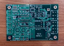
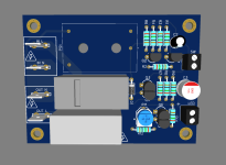
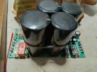

The power supply

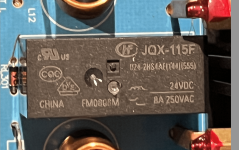
The power supply is beefed up with a couple of Nichicon 180uF 600V, bypassed with 0.1uF MKP; don’t cheap out on the voltage ratings. Additional filtering for the low-level stages with 2x50uF by JJ, bypassed as well; these are slightly less good than the Nichicon, with D = 0.2 vs 0.1 for the Japanese, after reforming. I also added snubbers and a ground breaker.

05-Leak-ST60-V1.25-PS.png


The sim

06-Leak-ST60-63h2e.png

This looks good on screen: THD down an order of magnitude, open-loop bandwidth up >15x.
Life is good… just DON’T BUILD THIS!

The tube line-up for the measurements

Pos.IdStatusBrandTypeIa (mA)Gm (mA/V)
V3R1NOS=C= / SEDEL348210
V4R3NOS=C= / SEDEL348310
V3L2NOS=C= / SEDEL34709
V4L4NOS=C= / SEDEL348110
V2R11UsedRCA12BH7A9.3/9.62.9/3.0
V2L10UsedRCA12BH7A9.0/10.22.2/2.6
V119UsedSiemensE81CC7.0/8.2
V5NOSSovtekGZ34

NB1: Ia & Gm are from my Metrix U61B tube tester – They are not operating conditions in the amp. And yes, V3L is quite a bit off, even though I paid the price for a “matched” quad.
NB2: the E81CC is probably a relabeled Tesla. They’re alright.
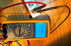
The reality

Life is hard. The output transformer is hard. Modeling the output trafo is just as hard. Measuring this whole affair is not any easier.
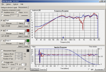
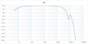
After implementing all the mods and tweaking the balance pot of the PI for minimum THD, I played it safe and did an open-loop test, so far so good:

07-ST60 L 1W OL.png


The open loop performance is not too shabby. I even suspect I could live with it as is, maybe with an ECC82 at the input to further reduce the gain, or even omit it all together, à la Fender.

But as soon as I close the FB loop, it oscillates, of course. This is expected, but the OPT model I’m using rules out any solution by simulation. Also, the limitations of my digital instrumentation make me blind: anyone sees anything beyond the right-hand side of the chart above? Too bad, it’s the limit of the sampling frequency.
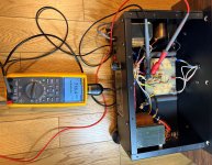
The archeology

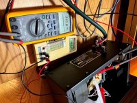
A little digging brings out some long-forgotten treasures: a vintage HP 3400A RMS voltmeter, a B&K 3010 function generator, pen, paper, and Excel. I know, a gadget like the Analog Discovery 2 would make my life less miserable, but I don’t have it. Or maybe E1DA’s Cosmos ADC: it should do 384KHz; this one is on my to-buy list. Anyway, here’s what gives, with my vintage all-analog lab:

Open loop, no compensation:

08-ST60-UL-1V-OL.png


Voilà: the dip at 70KHz and the peak at 90KHz are compliment of the OPT and ignored by the digital gear. Who says life in audio stops at 20KHz? Gimme 1MHz anytime!

Don’t pay attention to the anomaly at 10Hz, probably a human error: remember, it’s pen and paper time. And the early roll-off of the bass is caused by the small cathode bypass.

Now I can trial-and-error (not a verb) my merry way. Simple enough:
  • Feedback resistor is 1.2K
  • Drop the lag-zero resistor R21.
  • Remove the lead cap C9 for the moment.
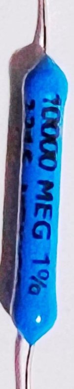
  • Mess with the lag cap C16. The OK-ish range is between 200 and 680p. I picked 390p, 630V polystyrene because that’s what I have.
  • Mess with the lead cap for the least bad compromise: it moves the peak up/down and left/right a bit; the OK-ish range is 1-2nF. I chose 1680p: 1nF // 680p, polystyrene too; the choice is also inventory bound. There’s no magic value that eliminate the resonance.
The open-loop gain is 146 or 43dB.
The closed-loop gain is 17.5 or 25dB, for 18dB of feedback.
The overall stability margin is better than 6dB.


Closed loop, ultra-linear:

09-ST60-UL-1V-CL.png


Triode:

10-ST60-Triode-1V-CL.png


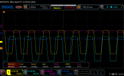
Square wave UL mode 8R load

11-ST60-UL-8R.jpg


Just a tiny bit of oscillation caused by the self-resonance. Patrick Turner (RIP) suggested the use of a small ferrite (evil!) inductor. Me, I see no reason why I should let in yet another reactive meanie, even an air-cored one, so I just ignore it.

Square wave UL mode 8R+1uF load

12-ST60-UL-8R1uF.jpg


Square wave Triode mode 8R load

13-ST60-Tri-8R.jpg


Square wave Triode mode 8R+1uF load
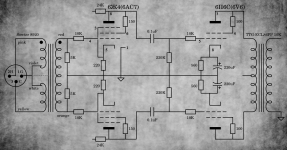
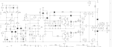
14-ST60-Tri-8R1uF.jpg


Final schematic

15-Leak-ST60-V1.25-Final.png


I’m attaching all the LTspice stuff, including the stolen ones. If I forgot to give credits to any rightful owners, please take this as my group apology.

Spice: postmortem

The first output transformer model I used is from McLean; it doesn’t model the parasitic capacitances, and so the self-resonance doesn’t show up. Of course, you can add series/parallel caps externally, but I don’t feel comfy with the results: in order to approximate the experimental findings, I have to add series caps (prim to sec) of the order of 10nF instead of the measured 2-3nF, which doesn’t add up.

The second model is from Ite, it supports parasitic capacitances, but it also has similar discrepancies as the first one.

Any output transformer AND LTspice guru out there?

Btw, in LTspice, the .ac command almost always converge; .trans will converge if the circuit is not oscillating too badly. IOW, during a .tran sim, if nothing useful happens after a few seconds, halt and add more compensation.

Totally OT side note: the new version of the forum software no longer limits the length of a post. However, you can't attach more than 20 items at a time.
TBC...

Attachments

  • 10-ST60-Triode-1V-CL.png
    10-ST60-Triode-1V-CL.png
    48.4 KB · Views: 286
  • 16-Leak-ST60.zip
    16-Leak-ST60.zip
    31.4 KB · Views: 147
  • Like
Reactions: OldHector

Cambridge Audio - Intermittent Remote

Hi,

Not actually an amplifier problem but I suspect it might apply to Cambridge Amplifiers.

I have a Cambridge Azur 640H music server (actually got a few because I like playing/repairing them🙂). One of them has started to develop a problem with the remote control - it will work fine but after a while will stop working. If I power off and leave for a while the remote will work again. It is not the remote because I have a couple of them and get the same problem with both remotes, and if I connect up a spare 640H the remotes work fine however long it's switched on.

Any clues where I should start looking - is it likely to be an internal component problem or software?

Thanks

Alchad

6V6 balanced amp

A nice and simple amp, but efficiency is terrible..
Used with full range speakers (Fane 12-250TC), 2-3W seems to be enough most of the time so I tried first everything triode connected.

I may try the 6AC7 in pentode mode, because gain is a little bit low.
Why not 6V6's in pentode mode too, and plate to cathode feedback.

To me, it sounds quite good, but no "magic". Not soft, not harsh, without NFB.

6V6 may not look very sexy triode connected when looking at the curves, but they seem to perform well.

Have to try the zener trick between grid/cathode of the 6V6, to minimize blocking distorsion, may be interesting for low power amps..

Attachments

  • 6v6.jpg
    6v6.jpg
    430.9 KB · Views: 241
  • 6v6pp1.jpg
    6v6pp1.jpg
    316.5 KB · Views: 159
  • 6v6pp2.jpg
    6v6pp2.jpg
    296.9 KB · Views: 165
  • 6v6pp3.jpeg
    6v6pp3.jpeg
    220.9 KB · Views: 140
  • 6v6pp4.jpeg
    6v6pp4.jpeg
    191.5 KB · Views: 148
  • 6v6pp5.jpeg
    6v6pp5.jpeg
    319.8 KB · Views: 225
  • amp.png
    amp.png
    932.4 KB · Views: 245

NAD C316 BEE Bad channel can it be the relay?

Good day everyone, this is my first post here so hoping that some more knowledgeable person knows a little more than I do.

I have a NAD C316 BEE. One of the speaker channels is super crackly.

I have plugged my headphones into the system and both channels are working fine. This led me to believe that it is probably the relay that has broken being the last thing between the headphones and the speakers. Maybe I am wrong?

I have tried tapping the relay lightly but to no avail.

IF it is the relay I can probably change it myself as I have had a little experience with renovating a 1960's B&O Beogram 1200 and plenty of soldering there.

I have attacehd an image of the relay. Would someone be able to:

1. tell me if it could be somehting else other than the relay?
2. If it sounds like the relay, (happy to change as they are cheap) but point me to an appropriate replacement, there are so many variations out there. I have managed to find similar ones, same Vdc, 8A etc but then all the talk of pins got mea little confused.

Im based in Sweden so any European online store would work well.

Thanks in advance for all your help.

Matt

Attachments

  • Screenshot 2024-01-29 at 12.23.19.png
    Screenshot 2024-01-29 at 12.23.19.png
    425.8 KB · Views: 121

PCB: low voltage On-Off switch drives AC mains relay \ includes soft start .. H9KPXG

ALL SOLD!


Hi,
I offer here a pcb.

Link to the thread.

Costs 10€ 7€ each pcb (because 2oz copper weight, DHL shipping and my favourite the customs fees :-( ).

Shipping in padded envelope (not insured, not tracking) to
  • Germany (without islands): 2,50€
  • Shipping in EU: 4,50€
  • UK: 10€ as small parcel (because Brexit & new custom laws, not insured, not tracking)
  • other countries please ask

Attachments

  • Softstart.jpg
    Softstart.jpg
    390.4 KB · Views: 1,138

Transistor based board for power ON/OFF using anti-vandal momentary switch and LED indicator

Hello everyone!

Currently, only the LTSPICE simulation has been completed. Moving forward, I plan to share completed schematics, gerbers, and a BOM. Additionally, I'm working on a bidirectional LED driver based on an H-bridge.

I want give shoutout to @Extreme_Boky for suggesting the idea of a transistor-based flip-flop!

This board will enable DIYers to integrate ON/OFF functionality into any project. The separation of high-voltage switching from the low voltage logic is achieved through a 16A non-latching relay with 360Ω coil. Board allows for a nice low voltage switch, anti-vandal type, and most of those feature a built-in LED ring. A compact 1W MeanWell SMPS is utilized to power the board at all times to monitor user input.

Biggest reason for choosing a transistor-based design for this board was to minimize power consumption. During idle operation, the board will consume only 2mA, primarily for monitoring user input. When the user presses the button, the flip-flop switches to its alternate branch, activating constant current sources for the relay and LED. The LED's brightness can be adjusted by varying the current from 0.3mA to 20mA. The relay driver circuit incorporates a 15ms delay to latch the relay at full 33mA current, which then reduces to 14mA. As a result, during normal ON operation, the board should consume only approximately 20mA.

Feedback and suggestions are highly appreciated!

Draft of the board in 3D is ready and attached!

Attachments

  • sch-tr-pwr-btn.PNG
    sch-tr-pwr-btn.PNG
    14.9 KB · Views: 214
  • combined-transistors-one-LED.asc
    combined-transistors-one-LED.asc
    4.2 KB · Views: 68
  • 3d-1.PNG
    3d-1.PNG
    36.2 KB · Views: 192
  • 3d-2.PNG
    3d-2.PNG
    30.4 KB · Views: 185

Onkyo TA-6511 problems with sound...

"It's ONKYO TA6511, sorry for the typo."

Hy,

Before I start boring everyone with the back story:
I have problems with sound, some female vocals have "robotic voice", here is the 3khz test tone recorded from computer and played back with the player (recorded with phone mic tho, as I don't have line in on pc):
3khz recorded and played back

Can this be caused by wow & flutter issue?
Any other possible reasons?

-While recording the sound is ok.
-I cleaned heads and capstan with 99% alcohol, pinch roller with mild soapy water.
-I have 3 bought sealed Maxell SQ Position High 90 cassetes and it is the same on all of them.
-I did FF/RWD prior to recording.
-I had tryed with auto bias calibration & without.
-dB meters are just hitting 0dB.
-Dolby off.
-I have only one song that I had recorded with my old AKAI before it died and it plays that one good, but this doesn't tell anything as I can only hear the error on some female vocals.


More on the sound:
On some songs where there are strong female vocals and words are singed long... like for example "I can't leaveeeeeeeee" that "leaveeeeeeee" sounds robotic, almost like a light computer lag or as producer would apply beat cut with light intensity over vocals.

PEOPLE WITH PRODUCING / MIXING KNOWLEDGE WILL UNDERSTAND THIS PART:
On one song, when female vocals starts, it sounds like vocals are sidechained to the instrumental limiter with way too much sensitivity... Instrumental gets too quiet and after some time the mix just falls apart... kinda like one would listen to mix that went bad, like it would be mixed by a rookie. Like a muddy mix, where instruments fight with each other for space in spectrum and music is not flowing / breathing as it should.


The Tape deck:
I had bought it 2 days ago, other than that problem it works awsome, at first I couldn't tell the difference between the tape and digital source.
It is in good condition inside and out, no signs of moisture, I can't see any leaky caps, not too much dust inside.
Will order new belt, current one is looking used, but not bad.

I really hope it is the belt, but I'm not holding my breath over it.

Any suggestions?

Thank you 🙂

Acoustat Interface MK-121-2: Example of Measuring the DC High Voltage

Purpose
  • To share a rudimentary method for monitoring the DC high voltage with my Acoustat Model 2 speakers.
  • To record the time required for high voltage buildup, and stability of the high voltage with time.
Test equipment
  • While an electrostatic voltmeter is the preferred instrument for measuring DC high voltages, in lieu of an electrostatic voltmeter a simple approximation can be made using a standard multimeter and an ultra-high resistance attenuator.
  • 1000:1 voltage divider. For the high resistance attenuation resistor, I used a 10,000 Megohm, 1 Watt, 1% tolerance resistor from Ohmite, part number MOX-750231008FE (Fig. 1).
MOX-750231008FE(OHMITE).jpg

Figure 1. Ohmite 10,000 Megohm attenuation resistor.
* This 10,000 Megohm resistor was connected to the input of my Fluke model 289 multimeter of standard 10 Megohm input resistance to provide a simple 1000:1 voltage divider.

Safety precautions with high voltage
  • Common sense with safety, all connections and disconnections were made with AC power off and high voltage section fully discharged.
  • With multimeter leads rated maximum 1,000V DC, to minimize risk of high voltage leakage I placed a plastic foam sheet to insulate the positive (Red) lead from chassis ground (Fig. 4).
Preparation
* This report follows on from previous reports posted to the diyAudio site:
a) "Acoustat Magne-Kinetic Interface MK-121-2 - A Successful Restoration". https://www.diyaudio.com/community/...ace-mk-121-2-a-successful-restoration.404764/
b) "Acoustat Stator Wire Repair: Hints and Lessons Learned". https://www.diyaudio.com/community/...wire-repair-hints-and-lessons-learned.404881/
* Reason, measured voltages could shift or be unsteady if the high voltage ladder circuit is weak or in need of repair, or stator wires are loose/bent touching the diaphragm.

Test method
* Following figures show examples of wiring connections, and subsequent measurements with the multimeter and Acoustat MK-121-2 interface.
Mains_AC_Voltage.jpg

Figure 2. Measured input of Acoustat MK-121-2 interface, 114.5V AC / 50 Hertz.

104333_AC_Frequency_Transformer.jpg

Figure 3. Measured output of bias transformer (input to high voltage ladder) shows 50 Hz, approx. 716V AC.


* One end of the 10,000 Megohm attenuation resistor is attached to the red wire terminal at output of high voltage ladder feeding the panel, with other end of the 10,000 Megohm resistor connected to the positive lead of the multimeter - note plastic insulating sheet as a safety caution (Fig. 4). Negative lead of the multimeter is connected to chassis ground.
104333_HV_Panel_1.jpg

Figure 4. Measurement shows approx. +5V DC, corresponding to a panel voltage of approx. +5 kV.

* With the Fluke 289 multimeter connected to a Windows PC for data logging, the setup was powered up from cold to observe the time required to reach full voltage (Fig. 5).
Fluke_HV_104333_Panel_In_Power_Up.png

Figure 5. Logging of time to reach high voltage.

  • Again, with the Fluke 289 multimeter connected to a Windows PC for data logging, stability of the high voltage was recorded against time. One example of these time slice recordings is shown in Fig. 6.
  • The observed voltage fluctuation was about 1%, although these fluctuations might be due to variation in the input AC line voltage, or noise pickup from exposed test leads with the chassis top cover removed.
Fluke_HV_104333_Panel_In_Steady_State.png

Figure 6. Example of high voltage stability vs. time.

Final notes

  • This report described a rudimentary method for monitoring the DC high voltage. As a tiny amount of current (typically less than a microamp) will drain through the attenuation resistor and multimeter, there will be some inaccuracy. Nevertheless, the method described can be useful for general measurements, troubleshooting, comparing the performance of one interface vs. another etc.
  • From these measurements it was reassuring to see the full high voltage achieved in less than a minute (Fig. 5). This agrees with my observations, these Acoustat speakers play beautiful music and sound fantastic within just a few minutes of powering up.
  • A further reward is the sound quality continues to improve over the next several hours, I don't know but perhaps it's because the diaphragm is stabilizing or other factors, as the high voltage shows very stable behavior with time (Fig. 6).
  • As mentioned in the two reports, "Acoustat Magne-Kinetic Interface MK-121-2 - A Successful Restoration" and "Acoustat Stator Wire Repair: Hints and Lessons Learned", I purchased these speakers new in 1980, it's amazing that after 44 years they still sound fantastic, as good or better than new.
  • And finally, if you try this method, please be respectful at all times of high voltages and take adequate safety precautions.

Attachments

  • MOX-750231008FE(OHMITE).jpg
    MOX-750231008FE(OHMITE).jpg
    28.5 KB · Views: 82
  • MOX-750231008FE(OHMITE).jpg
    MOX-750231008FE(OHMITE).jpg
    24.6 KB · Views: 77
  • Mains_AC_Voltage.jpg
    Mains_AC_Voltage.jpg
    160.7 KB · Views: 76
  • 104333_AC_Voltage_Transformer.jpg
    104333_AC_Voltage_Transformer.jpg
    631.3 KB · Views: 89
  • 104333_Fluke_High_Voltage_1.jpg
    104333_Fluke_High_Voltage_1.jpg
    164.1 KB · Views: 73
  • 104333_HV_Panel_1.jpg
    104333_HV_Panel_1.jpg
    157.1 KB · Views: 75

Are Pioneer PWY1003,PWY1004,PWY1008,PWY1009<PWY1010 optical pickups the same pickup

Are pioneer PWY1003,PWY1004,PWY1008,PWY1009<PWY1010 optical pickups the same pickup

Hi, I am looking to replace my cd players laser optical pickup. When I physically look at mine which is the pioneer PWY1003,and compare close up pictures of the rest of the PWY1004, Pwy1008, PWY1009,and PWY1010. They all look exactly the same from the front and back. Not one slight difference I can see from mine. I thought the ribbon pin count would be different,But even it is exactly the same with 17 pins. If this is the case.Can I use any of those models to replace my cd laser optical pickup in my pioneer PD7050 cd player. Thanks

For Sale Lot drivers Sonus Faber Venere

Hi,
for sale, lot Sonus Faber Venere.
Mid/woofers/Tweeters
Crossovers
Speaker terminals banana

Each driver tested with multimeter. No tested with sound or within a system.

I purchased a lot with turntables, amplifiers, ... This was within the lot, I have no use for it. Hope someone could make something from it.
I could ship, but thats heavy! Local pick-up preferred in Berkeley, CA, USA.

$500, would be open to offers in the coming days depending on the demand.

Attachments

  • PXL_20240327_161820373.jpg
    PXL_20240327_161820373.jpg
    747.8 KB · Views: 102
  • PXL_20240327_162139629.jpg
    PXL_20240327_162139629.jpg
    565.8 KB · Views: 101
  • PXL_20240327_162143316.jpg
    PXL_20240327_162143316.jpg
    806.9 KB · Views: 95
  • PXL_20240327_162341211.jpg
    PXL_20240327_162341211.jpg
    405.4 KB · Views: 100
  • PXL_20240327_162345569.jpg
    PXL_20240327_162345569.jpg
    625.1 KB · Views: 100
  • PXL_20240327_162517000.jpg
    PXL_20240327_162517000.jpg
    844 KB · Views: 99
  • PXL_20240327_162534734.jpg
    PXL_20240327_162534734.jpg
    652.5 KB · Views: 101
  • PXL_20240327_162538291.jpg
    PXL_20240327_162538291.jpg
    842.6 KB · Views: 86
  • PXL_20240327_162555871.jpg
    PXL_20240327_162555871.jpg
    606.9 KB · Views: 87
  • PXL_20240327_162600761.jpg
    PXL_20240327_162600761.jpg
    621.4 KB · Views: 97
  • PXL_20240327_162603567.jpg
    PXL_20240327_162603567.jpg
    590.1 KB · Views: 91
  • PXL_20240327_162613171.jpg
    PXL_20240327_162613171.jpg
    425.4 KB · Views: 94
  • PXL_20240327_162623637.jpg
    PXL_20240327_162623637.jpg
    939.2 KB · Views: 103
  • PXL_20240327_201518134.jpg
    PXL_20240327_201518134.jpg
    718.4 KB · Views: 100
  • PXL_20240327_201522811.jpg
    PXL_20240327_201522811.jpg
    548.2 KB · Views: 96
  • PXL_20240327_201525427.jpg
    PXL_20240327_201525427.jpg
    266.5 KB · Views: 91
  • PXL_20240327_201530120.jpg
    PXL_20240327_201530120.jpg
    256.3 KB · Views: 93

F5M using F5 v3.0 PCBs

Hi all, and thanks in advance for taking the time to read my post. I am in the process of putting together an F5M using the F5 v3.0 boards sold in the diyaudio store. I used the schematic and info provide in post #70 in the F5M kit thread that provide detailed info on values and I checked and they are absolutely correct. I thought I implemented that exactly on the F5 v3.0 boards, but each channel is failing the dim bulb test (glowing very bright, r7 and r8 hot immediately), and I am at a loss as to why. Continuity testing is not showing me any issues, but I am certain if I apply full power, I'm going to see white smoke.

Observations:
  • Power supply tests out fine with +/- 27 vdc. No issue with bulb test. I’m using the universal board from the store with an AS-4220 (had on hand)
  • Jfets were purchased new from the diyaudio store
  • Tested resistors before soldering and confirmed values
  • Tested mosfets, and v+/-, inputs/outputs for short to ground , none found
  • No solder bridges or cold joints I could find
  • I am getting .57 vdc across R7 and R8 with both pots turned fully counterclockwise as soon as power applied. Exact same reading on both channels
  • The LEDs on the power supply do not light when either channel is connected to power. I assume this is because of excessive current draw from channel board
Here is how I stuffed F5 v3.0 boards.

F5 v3.0 boards
R1 – 15k
R2 – 33k
R3 – 43r (1w)
R4 – 43r (1w)
R5 – 2.2k
R6 – 2.2k
R7 - .47r (3w)
R8 - .47r (3w)
R9 – 560r
R10 – 510r
R11 – 510r
R12 – 560r
R13 – link, 0r
R14 – link, 0r

Q1 – 2SK170
Q2 – 2SJ74
Q3 – IRFP240 (had on hand vs the 140)
Q4 – IRFP9240 (had on had vs the 9140)

P1 – 5k, 25 turn
P2 – 5k, 25 turn
P3 – link outer pins, 0r

All other component locations on the v3.0 boards are not populated which should result in a F5M that matches the official schematic (aside from R1 & R2).
Appreciate any thoughts on how to proceed. Thank you!
PS.JPG
F5M.JPG

Ping Scottmoose - Enclosure question

Greetings and Salutations,

Do you have a (no holds barred) tapered stand mount design for the MA 10.3 in the style of the Storm Shadow v.2?
The Vas is a bit on the large side I know for a strand mount but still....
I have no idea if the MA 10.3 even lends itself to a tapered TL but thought I would ask.
If not presently in existence is this something that could be done?


Thanks

Hypex UCD700 module, tranformer, power supply

1 unit ucd700 (u can get one from ebay if need stereo)
1 unit tranformer ( u can power up 2 UCD700 smps p.s)
2 units of UCD-PS-700 for 2 UCD700 module

Asking 700usd include ship and paypal fee

Attachments

  • 1712585244092.jpg
    1712585244092.jpg
    320.8 KB · Views: 68
  • 1712585244050.jpg
    1712585244050.jpg
    241.7 KB · Views: 71
  • 1712585244008.jpg
    1712585244008.jpg
    233.4 KB · Views: 66
  • 1712585244175.jpg
    1712585244175.jpg
    352.7 KB · Views: 66
  • 1712585244133.jpg
    1712585244133.jpg
    328.8 KB · Views: 66

For Sale A Pair Grundig Oval 12 x 8" Vintage Mid-woofers, 2 Ohms DC both

For sale a Pair Vintage Grundig Oval 8" X 12" mid-woofers. They bot tests 2.2 Ohms DC with my DMM. That would be around 3 Ohms for AC power (signal)
Came out from a Grundig Radio, turntable console driven by single ended tube amp.
I tested and both sound excellent even do one has a small tear on the surround. Please see the pictures for that.
Easy to fix but I leave that to the new owner. It does not effect the sound at all, not distort. Both of them sound great!
They were driven a pair EL84 Single Ended tube amp, they are very loud and give warm sound.
Again they are very sensitive speakers, I think it can be use as full-range drivers with the help of super tweeters with a SE tube amp in a small medium room.
The asked price $125 CAD is FIRM, pick up only in Toronto at Keele and Lawrence area.
I do not want to ship.
Willing to demonstrate before pick up.
Thanks for the interests.
Greetings gabor

Price REDUCED $110 CAD!

Attachments

  • IMG_0001_3.JPG
    IMG_0001_3.JPG
    243.3 KB · Views: 148
  • IMG_0002_3.JPG
    IMG_0002_3.JPG
    236.4 KB · Views: 125
  • IMG_0003_3.JPG
    IMG_0003_3.JPG
    273.7 KB · Views: 142
  • IMG_0004_3.JPG
    IMG_0004_3.JPG
    259.4 KB · Views: 122
  • IMG_0006.JPG
    IMG_0006.JPG
    182.9 KB · Views: 123
  • IMG_0005_2.JPG
    IMG_0005_2.JPG
    261.3 KB · Views: 120
  • IMG_0012.JPG
    IMG_0012.JPG
    209 KB · Views: 130

Opinion needed regarding capacitor value on parts list

Hey, 1st I’d like to thank those who responded to my inductor post. Thank you

The project I’m working on is a set of boards for a Bryston amplifier I ordered from Aliexpress.

So now I’m getting ready to order the capacitors for the project. I’ve attached 2 images of the parts list showing the caps required for the build. I used google translate to translate the Chinese. The 1st image is for the non-polarizeded caps and the 2nd is for the electrolytic caps.

I noticed that some of the non-polarized values had a “p” after the value, which I assumed was for “pico”. The others had no markings after the value. Being a novice, I assumed the others were “micro” by default. Just to confirm my assumption I contacted the seller to verify if I was correct, they answered “yes”.

While doing some research about capacitors I found that there’s a numerical code for determining the value of caps. I compared the values on the parts list to a table of standard value codes and found that the values without the “p” corresponded with a value in the table.

So, now my question is in regard to the values listed for the non-polarized caps. Should I go with my original assumption and the seller’s confirmation and order those values using “uF” or order them using the values that correspond with those in the table? And as you know there’s a big difference between 220pF and 221uF🤪

Thank you for taking time to read this post and I’m sorry it’s so long. I didn’t want to leave anything out and in case I did leave out any details, let me know.

ML

Attachments

  • IMG_0456.jpeg
    IMG_0456.jpeg
    86.5 KB · Views: 58
  • IMG_0457.jpeg
    IMG_0457.jpeg
    51.6 KB · Views: 54

Cabinet retrofit

Hello,

I've just inherited these ~70s speakers; they sound dreadful. However I really like the solid wood cabinets.
I'm completely new to diy speakers but I'm comfortable with electronics so I'll want to mess around with these some more later but for now I'd just like to get them playing decently.

A lot of you guys recommend building a proven design first but I haven't been able to find one that's particularly similar.
The closest I've found in size is this one: http://www.troelsgravesen.dk/STUDIO-101-mkII.htm but the design is very different or this one https://sites.google.com/site/undefinition/bookshelf-speakers/virage but the sizes are also quite different.
So right now, I'm thinking of looking for a 7/8" and a 1" dome tweeter similar to the builds above.

Has anyone else retro-fitted a cabinet?
What are the big things that I need to consider?

Inside dimensions: 55cm x 26cm x 21cm (to the bottom of the mounting board) HxWxD ~ 30 litres
Height available to mount speakers is around 41cm, inside is completely empty.
1712399188972.jpeg
1712399194969.jpeg
1712399206782.jpeg

Another Behringer NX3000 repair

hi, i have mostly fiddled around one chip classd solutions and bought broken nx3000 to repair and learn a bit. so sorry if this is a bit newb question.

classic protect fault, one output fet shorted(gate short) bought some SUP90100E fets to replace original IRFB4227 as there is half RdsON and bit higher current rating, lower Qg, and i thought that was bit too easy.

fast forward to when parts arrived and replaced, amp turned on worked for 10 seconds or so, and blown another fet again, but this time it was not shorted gate but drain source short.

i put one of old 3 fets in place to get some scope shots from gate outputs after i checked all zeners and diodes in drive circuit, i turn amp on just few seconds wait only for scope to get data and turn it off so i can see what is going on.

attached is picture of all 4 gates, low side is correct at +-10ish Volts, but high side has gate swinging +-80V or full rail voltages, i cant wrap my head around how is this possible and already done all i can so i post here for someone smarter to point me in right direction.

amp is half bridge, and gate driver ic is IRS20957S with some i think its called totem pole pnp npn transistors. croped schematics also attached.
thank you and have a nice day.

Attachments

  • RigolDS10.png
    RigolDS10.png
    30 KB · Views: 327
  • crop.png
    crop.png
    106.9 KB · Views: 408

Reflected Sound Design Principles Bose 901 style

Hey all,
I've been running through some scenario's in my mind and i was hoping to get some input from the crowd on here,
I've been diving into the operating principles of the Bose 901,

How you all think the reflected sound would be affected if using larger full ranger drivers, say 2 x 12inch full rangers vs the 8 x 4inchers on the back face?

Or ditch the full range entirely and use a combination of mid-woofers and two horn loaded CD's on the back face?

Just curious if people have thoughts on this.

Tweeter Q change with series resistor for attenuation?

Tweeter: Visaton DT94 (8 ohm)
https://www.visaton.de/sites/default/files/dd_product/DT 94.pdf
Woofer: Dayton Audio RS150P-4A (4 ohm)
https://www.daytonaudio.com/images/...rs150p-4a-reference-series-specifications.pdf


I replaced the drivers in my parents in-wall rears (blown tweeters and 4oz magnet woofers). Reason being they're going to be used as rears in a mid- fi larger home theater setup (Denon 3700 5.2.4)

I decided for the widest dispersion to use a cone with ~4.25" diameter and a 0.8" tweeter, crossed low.

The woofer is 2nd order at ~1700hz, the tweeter rolls itself off 2nd order at 1700hz. I put a cap on the tweeter for thermal protection (~1300hz)

I'm not concerned about hf distortion or cooking the tweeter - I listened for distortion and measured temperature after pink noise, and everything is fine at levels well above listening.

No, I didn't sim things, but it sounds very good. I chose things to keep everything as simple as possible (tweeter has a q of 0.54 and a flat impedance curve which is up just 10% at resonance/woofer is flat for 1.5 octaves above xover and has perfect horizontal dispersion past 80 degrees at xover)

I want to attenuate the tweeter just a little bit. My concern is: if I put 1 ohm in series with it, will q change and screw up the phase?
If yes, no big deal, the Denon 3700 has XT32 speaker/room correction and these are only rears.
I believe the increased efficiency between 9 and 16khz which ranges +1.5-4db, averaging about 2.75, is what causes the tweeter to sound bright - making want to attenuate it some. Both drivers are listed as 90db /2.83v. So maybe I should just leave it as is and EQ the tweeter?

Most importantly, will I induce ringing in the tweeter by adding series resistance while using its natural rolloff (q~0.5) as the crossover point? If so, is there a maximum amount I can add before things become audible? I assume ringing will manifest itself as a lack of clarity, which I don't want, especially around 1700hz - the ear is sensitive there and speech intelligibility would be affected (not that people talk through the rears that often, but still)

wanted: accuphase e302 schematic or service manual

hi i was trying to restore an accuphase e302 with burnt parts, Some has gone thru these amp and install some non complementary parts for the pre drivers stages and it did made the amp oscillate and blow the output transistors and burt some other parts it would be helpful if i had a schematics for reference and i would greatly appreciate it. Thank you. My email is jmdimayuga@gmail.com

free and/or cheap in Los Angeles!

Hello,

Clearing out the garage, and realized there are too many speaker projects I'm simply not going to get to. Everything is for pickup only - I'm not shipping anything! Have a 9 month old 2 year old at home, so barely have time to 💩, let alone package things and ship them. Probably have even more once I dig around some in the garage.

cheap:

$20 - 6" flared Precision Port

$30 - very high end 18" cast frame passive radiator from Exodus Audio (Kevin Haskins shop), w/ weight kit

$95 - older LC Audio Predator based amplifier with huge power supply. Nice case is engraved with 125 RMS @ 8 ohms, 250 @ 4 ohms, and 500 @ 2 ohms. Serious power supply! Heavy!
L C Audio Technology / Predator SE (not exact but approx. same amplifier)


Cheers,
Tal


gone:

24" diameter x 24" height Sonotube, with three 24" 3/4" wood endcaps (intended double thickness for driver side)

single cheap and old black vinyl Infinity 8" two way bookshelf speakers with the woofer missing (had a pair but think I accidentally disposed of one, sorry)

12" car audio box, but well made, though extremely ugly. Braced, sealed, and maybe 1.5 cf from memory, made by a friend for his car and donated to me for Audio Purposes.

$20 Panasonic SAXR-10 receiver with switching amplifier (actually digital/powerDAC, not class D). Unfortunately, doesn't have the remote, so can't select digital inputs, so goes through A/D conversion for the power amplifier. :-( If you get a remote for it you have a very nice amplifier!

$25 (what I paid for it): HSU 10" ported subwoofer, their original "True" subwoofer, w/ dead amplifier. Well made 10" box, with two large flared ports, and one port bung for variable tuning.

12" car audio box, sealed not ported, the ubiquitous carpeted kind. Actually, have two of them.

triple 12" home subwoofer box, used a Peerless XLS 12" driver with two XLS passive radiators (covering the front three faces of the rectangular box), with a huge cutout for Keiga's 1000 watt plate amp. obviously, no drivers or amplifiers included.

$30 Audiocontrol Model 200, has a hum when on. Otherwise nicely made amplifier with lots of features. https://www.audiocontrol.com/downloads/home/discontinued/architect-model-100-200/Architect Model 100_200 Owners Manual.pdf

$25 - enclosure only for highest-end JBL studio subwoofer 6312SP, ported, carbon-fiber baffle, uses fancy push-pull voice coil with neo motor
$45 - driver from above, neo motor, dustcap sadly torn/pushed in; heads-up: it's a 2 ohm driver! LSR6312SP | JBL Professional Loudspeakers

$45 harmon/kardon AVR520 receiver I was using with a MiniDSP for active crossover projects as it has inputs directly into all 5 channels of the power amplifier (look on left for jumpers here 404 Not Found). Amplifier is rated at 75/100 watts into 8/4 ohms. https://img.usaudiomart.com/uploads/large/1243564-95c99170-new-old-stock-harman-kardon-avr-520.jpg

$75 - SVS 20-39PCi large vertical ported cylinder subwoofer. Either amplifier or driver damaged, but I think it's the driver. Pretty intense subwoofer!

$45 - Tannoy Di8 DCT coaxial 8" speaker, white, deconstructed. Was going to build this into a nice box for a center channel, but didn't get around to it. Have all of it, just the driver is not in the box, and the box is taken apart. Includes a spare tweeter! Click on Details from this link. Click on 'Details' in this link: Tannoy Di8 DCt Series Surface Mount Single Speaker - Black

$67 - NHT VS-2 speakers that I don't need. Very good MTMs in a piano black enclosure that go down cleanly and loudly to 75 Hz; designed by Ken Kantor for home theater.
  • Like
Reactions: Guerilla

EAR 834p clone weirdness - high frequencies dropped out

Posted this in another forum but figured I’d try here considering how helpful this community has been over the years.

Hi folks. I have a Zhili 834p clone with a separate PSU, the black and gold one. It’s been sounding pretty great. I upgraded the coupling caps a few months ago to VCAP ODAMs and it sounded even better. Just yesterday it sounded weird, sort of veiled and muffled. I confirmed by swapping in another phono pre as well as a couple of integrated amps. Did a bunch of tube and cable swapping, as well; I tried everything to the extent of my limited knowledge. All scenarios had same results with the 834p clone lacking highs regardless of whatever I swapped and all sounding great when the 834 was removed. I don’t know where else to look, would appreciate any insight or guidance you may have. My friend who gave me these caps and noted they may take some time to burn in and sound odd along the way, but this is a bit more pronounced or obvious than what I’d imagine cap burn in would be (myth or not..). I’m stumped!

Adcom GCD-600 turning on (kind of) while powered off

My GCD-600 cd player works ok while turned on. But the problem comes when powered off…. After a few minutes of being off, it starts to click (relay click) and the display turns on dimly. The clicking is erratic In tempo. If you turnt it on, the unit goes back to normal and works as expected.

im attaching the service manual, hoping that someone can share some light into this issue. Most probably is a cap that has high resistance, heats up and shorts the circuit to ground, maybe.

Any insight will be highly appreciated.

cheers,
Luis

Attachments

Kuba Arosa Stereo/Record Console with Telefunken Turntable (1958-59) help

Hi everyone,

I recently acquired a Kuba Arosa stereo/record console with a Telefunken Turntable in rough condition. From a few quick searches, I’ve found that it was produced from 1958-59, but little else. I know very little about vintage radios and turntables and even less about vintage wirings, parts, etc, but there are some obvious flaws which i will attach pictures of. Does anyone have any insights as to the potential issues with these systems?

I still need to purchase an updated plug, so as of now I have absolutely no idea how the systems function. If anyone has any suggestions about parts to buy in the meantime, it would be greatly appreciated. Thank you!!

Attachments

  • 4285BC13-22E5-4D66-9AC6-FD1BDC9E22BC.jpeg
    4285BC13-22E5-4D66-9AC6-FD1BDC9E22BC.jpeg
    268.8 KB · Views: 109
  • DFB8C72D-962F-48C3-8E6D-FE7BD057F90E.jpeg
    DFB8C72D-962F-48C3-8E6D-FE7BD057F90E.jpeg
    268.8 KB · Views: 94
  • 1B5177B6-4388-4BBC-929E-532BE0455730.jpeg
    1B5177B6-4388-4BBC-929E-532BE0455730.jpeg
    201 KB · Views: 90
  • 02F8752F-9502-4B13-AA3A-75963050B8F6.jpeg
    02F8752F-9502-4B13-AA3A-75963050B8F6.jpeg
    342.7 KB · Views: 90
  • 722D5429-C602-476D-9868-42FC49266539.jpeg
    722D5429-C602-476D-9868-42FC49266539.jpeg
    228 KB · Views: 94
  • 1BBEC262-3507-4C3D-B2D6-1AFE1C3105F6.jpeg
    1BBEC262-3507-4C3D-B2D6-1AFE1C3105F6.jpeg
    188.9 KB · Views: 94
  • 6A34E9F1-53DB-4AC4-9110-1D4943A911F2.jpeg
    6A34E9F1-53DB-4AC4-9110-1D4943A911F2.jpeg
    113.2 KB · Views: 97
  • C3E74C28-6A07-439D-9EC2-304BD1C877B6.jpeg
    C3E74C28-6A07-439D-9EC2-304BD1C877B6.jpeg
    243.1 KB · Views: 95
  • 6082A121-3C03-4B81-B409-596BDCE9EC9A.jpeg
    6082A121-3C03-4B81-B409-596BDCE9EC9A.jpeg
    146.2 KB · Views: 101
  • ACAAD124-3227-497F-9802-9A97553F7675.jpeg
    ACAAD124-3227-497F-9802-9A97553F7675.jpeg
    142.5 KB · Views: 93

Question about flare frequency and multi entry horns

I have been thinking about the flare rate of multi entry horns at the tap point

Is there a way of calculating the flare frequency for each point down a horn flare?

I saw somewhere that it could be done with this formula:

343/(4*PI*L12)*Math.log(S2/S1)

I am currently making a webpage to help with designing MEH, you can put in S1, S2, L12 then it will graph the highest frequency, cancellation notch and hopefully lowest frequency loaded by the horn at each tap point.

This is where I am at so far:

1712587110142.png


Doesn't look great but you can upload the slices output by ath or generate a conical horn

Large capacitor tuning technique

I have applied large capacitor tuning technique, by series a large capacitor to the woofer, to my closed speakers. In theory, it states that this action will result in changing the slope of the bass response from 12dB/octave to 18dB/octave. So, does it mean my speakers now will produce bass response close to the Third-Order Quasi-Butterworth of the vented box? And how about the transient response? Will it behave like closed or vented box?

Replicating Pre-amplifiers and Output Amplifiers from Legendary Machines? Ampex 200 Studer J37

I have searched the internet and have found no one that has done this. I have looked at the schematics of the Ampex 200A and the Studer J37, they are just simple class A tube amplifiers. I know the amplifier is only a part of the machine but it is the actual input/output. So if you where to built the circuit with the same tubes and the same values wouldn't that at least be reminiscent of the machine it was designed off of? An Akai M8 reel to reel for example. Most people strip these beautiful machines just to make a guitar amp from. Seems to me it would be very easy to replicate the circuitry form one without destroying antique gear (They say the decks are not that great, on paper yes, in reality they sound uniquely fantastic IMO). The schematics tell you everything you need to know.
  • Like
Reactions: rayma

Vintage Receiver Restoration

Hi folks,

I am restoring a vintage Criterion MkVII receiver which I saved from the land fields. With this post, I have two goals:

1. Get help with setting the correct bias in the power amp section

2. Get help with understanding the power amp circuit.

Little bit about the Criterion…It was the last receiver developed and sold by Lafayette. As a matter of fact, the company was closing doors when it came on the market. There is no information available other than the attached schematic that came weirdly, with the owner's manual. No budget for service manual or service afterwards. Personally, I think that it is a very clean sounding receiver and one of the prettiest of the era. It is very simple and elegant looking one.

With regards the first question above, I need to setup the DC bias, but I have no idea to what value and where to measure it. Normally, for class AB amp it is measured across either or both R21 and R23. Am I correct and if so, how do I calculate the proper bias voltage?

With regard understanding the circuit…here is what I think I know about it and a few questions at the end:

We are going to look at the left channel only.

Signal travels though C1 and is applied at the base of the left transistor of Q1 (Q1 is a supermatched pair of transistors in one enclosure) of the longtail pair comprised of Q1 and Q3 which forms the IPS. Overall negative feedback/closed loop gain is provided at the base of the right transistor of Q1 through the R11/C7.

The signal is taken from the collector of the left transistor of Q1 and applied to the base of Q5 which forms the VAS. after that one half of the wave (lets assume sinusoidal signal for simplicity) is applied to the base of Q11 and the other half through C11 is applied at the base of Q9. Afterwards it is easy, one half goes through Q11, Q15 and Q19, while the other goes through Q9, Q13 and Q17. Q7 is a voltage source and along with the STV4H's diodes and R17 form the bias spreader of the amplifier.


Here are the questions:

1. Is my general understanding of the circuit correct?

2. How come that the feedback is applied to both: the base of the right T of Q1 and Q5? I would expect that it is applied only to right T of Q1.

3. What is the function of C9 and C31?

4. Can someone explain the dynamics between IPS, VAS and the feedback gain loop?

Thanks in advance.

Best

Soundork


P.S. Here is a little interesting fact as a reward for reading this far: The only thing wrong with it is a bulging capacitor in the PS. The rail voltage is 50V and they have a cap rated at 50V max. Wicked weird…😊
Schematic Rev 1.jpg


1712282277101.png

2N2222A phono preamp

:cop: Thread split from http://www.diyaudio.com/forums/tubes-valves/156564-need-good-phono-stage-design.html
___________________________________________________________________


Phono preamps, Phono preamps.

Everyone wants a "good" phono preamp. And it must be tubes. Why..., must it be tubes, is my question.

I have been in electronics since 1952. And not once, have I a seen a great tube preamp; that did not require re-tubing.

Re-tubing a tube preamp, removes the balance and the smooth tones that was once its signature. You will spend large sums of money trying to get that sound again, that will never return. It will be close, but no cigar. Never! Again.

Why, because tubes are not made equal. The grid is the secret to its sound. And they are never made the same. Believe me..., I know. I worked at GE and Tung-Sol tube factories. And it does not matter what you do or how hard you look.

So I will tell you a great secret, one that very few know.

There is only one great phono preamp. And I designed and built it for the US Government in 1961. And it uses only three transistors. A transistor that was designed in 1956. That is still made today, for as low as 3 cent each per 100.

When I was young, I went to Bell labs, and met the people that were designing transistor chips for many other companies. They were starting to make silicon units. They gave me what they called the greatest transistor ever. They told me that thousands of different transistors will come after it, and people will over look its outstanding values, because they will misunderstand it. Or they will misunderstand its data values or they would not know how to read a transistor data sheet.

My the phone preamp used three 2N2222A. It is very, very quite.

You may being thinking, I am crazy. Yet allow me to lay some facts on you.

a. the max. noise level of a 2N2222A, is 4db. No more
b. its dc current gain is 50 to infinite, at 10na/10volts
c. its dc current gain is 75 to 325, at 1.ma/10volts. Which is much better than some of the more new transistor designs for high gain. Believe me, any thing above 375 in gain, is only better noise level. Not a better transistor. And its real Vceo is 50 volts, not 40 volts.

Once it is built, you will never want for another preamp. Because you will never lose that smooth warm tones of a 2N2222A. Will not believe your ears.

email me, if you are serious into audio, and I will send you the pcb. It is in CircuitMaker 2000 format.

Take Care

Ivey
  • Like
Reactions: JMFahey

Eiclone Input sensitivity

Hi guys,

I recently bought an Audio Research SP-9 MKIII, but I can't adjust the volume very well in my system ... the Eiclone amps (diytube project) seem to have a high input sensitivity.
As explained in the Audio Research's instruction manual, I tried to reduce the gain of the preamplifier by 6db, however it's still high.
Does anyone know the input sensitivity & input impedance of Eiclone?

Any comment would be very appreciated.
Thanks
Andrea

HOLMImpulse: Measurements in practice

The intention of this thread is to get practical feedback for my application: HOLMImpulse

HOLMImpulse is Non-Commercial freeware with full functionality (No limitations or trial periods) running on Windows XP/Vista

Download HOLMImpulse Here


Other diyaudio thread for theoretical discussions
I started a thread, which went rather theoretical:
http://www.diyaudio.com/forums/showthread.php?s=&threadid=144984
If you have theoretical questions/features/bugs/doubts then please refer to that thread.

The main goals of the application
  • Measure Impulse-response
  • Measure Frequency-response (Gain and Phase)
  • Easy and fast to use (Simply select your soundcard and click measure)
  • Work with any soundcard
  • Use the latest measurements techniques without complicating the interface
I would like your response
  • I know that there is no manual yet, I'm working on it...
  • Please post your measurements in this thread, it would make me very happy to some measurements and it would help me improve the tool.
Why I'm doing this?
When I started building my DIY-speakers I could not find any freeware satisfying my needs.
I believe that whatever you can measure you must measure instead of fabulating...
  • Does the grill make any reflections?
  • Is the relative phase correct?
  • Is the relative gain correct?
  • Is the tweeter broken?
  • How does my carpet or sofa table affect my impulse response?
  • ...
Above questions can be answered by HOLMImpulse even without a calibrated microphone, since you are often only interested relative measurements (Like above)
I have attached a measurement of my girlfriend 's speakers (Rega EL8), where the manufacture had the mid/woofer out of phase in the one speaker causing the dip at 4 kHz
(It's of course resolved now...)

Attachments

  • screenshot004.png
    screenshot004.png
    46.7 KB · Views: 8,079

Capacitor choice for Class-D amp recap

Hello!

I think I need to recap my Hypex FA plate amps after more than 5 years of service because they started to emite slight his/noise after powering them up. They came with very cheap/low tier caps from the factory.

The choice would be Nichicon UVZ or Panasonic ECA. The Panasonic is roughly twice the price of the Nichicon.

Would the extra cost of the Panasonic be worth or the Nichicon is also good enough?

Can I expect sound character differences between the two?

Thanks!

Do Transistors HFE drop after time/damage?

I have some Sanken 2SC3858 and 2SA1494s in T200 package pulled out of a Urei 6260 amplifier because one side has two of them blown. The rest of them all measure much lower hfe gain than the data sheets suggested. The NPN 3858s measure in the low 20s when the data sheet says it should be a minimum of 50.

So I was wondering if damage or age can effect HFE?

Reverse engineering BI-AMP modules

I own ADS L1590 speakers. They had bi-amplifier modules as an option for using them as the active speakers. The module internally consists of active crossovers and amplifiers for low- and high-pass sections. I'm going to enable their active biamplification mode. But I plan to use the better power amplifiers with the DSP instead of finding the very rare complete modules. So, the objective of this project is to reverse engineering the characteristic of the active crossovers. However, I'm not a professional electronics engineer or electrician, I have basic knowledge of electronics. I have tried simulations of the active crossovers. Here are the results.

Low-pass section:
Low Pass.png
lp-mag.png
lp-phase.png

High-pass section:
High Pass.png
hp-mag.png
hp-phase.png

Combined response:
combined-scheme.png
combined-mag.png
combined-phase.png

Could anyone verify my results? And how to obtain the corner frequencies and Q factors, I believer they are second-order, which are required to be used in setting the DSP?

Help! NAD C352 making loud crackling noise in L ch

I have a NAD C352 (2004) amplifier which has recently started making very loud crackling noise from L ch . It first started with soft crackling noise , lasting only for the first few min, after power ON and later the noise faded away with music playing properly on both ch. Now no music thru L ch. , only loud crackling noise, while the R ch is playing properly. Maybe the music is drowned behind the noise

During the initial troubleshooting , I found that the crackling noise is coming only from the L ch. (of both pre-amp out 1 & 2) regardless of volume control position, Offset- bouncy reading on L ch due to noise and under 2mV for R ch.
But if I remove the pre-power link from the rear side and directly connect thru power amp in, the output is proper without any crackling noise, no issues with offset.
Currently, for testing purpose , I'm using a pair of small 3" speakers, with series 47R (to reduce power)

All these years, no recapping was done, as recommended on many online forums and YT, largely due to cheap caps being used by NAD (perhaps, maybe they survived all these years due to active cooling fans). Slight browning underneath the PCB observed due to excessive heat dissipation (inadequate heat sink and undersized power resistors provided by NAD).

I have very basic troubleshooting skills and basic tools (cheap DMM & soldering kit) to carry out any further tests. If required , I have a friend , who has a DSO , ESR tester, variac, Fluke DMM, various capacitors and resistors for testing purpose in his LED lights mfg. company. The only problem is that I will have to carry the amp over there and work on it during office hours only.

I would be grateful to you all , with helping me solve this issue.

Repairs/Mods carried out in distant past by me (unrelated to the current problem)-
1. Installed 4 cooling fans, powered by ext wall wart, after the warranty period was over
2. Removed bad 20K balance control and replaced it with 10K+10K x 2 resistors (0.25W) (2009)
3. Reflowed transistors in preamp section due to audio cutting out intermittently (2009)
4. Removed tone defeat switch as its contacts went bad and shorted it with a link , such that the tone defeat was always OFF with tone controls working (2011)
5. Replaced the TL082 pair with OPA2134 and soldered missing 0.1 uF film bypass .
The other unconnected section of opamp was properly terminated thru 15K SMD input to gnd and output to gnd , output to input feedback (as the original TL082's unused section was left floating).(2012)
6. Basic dust cleaning/servicing carried out every year.

  • Locked
miniOnken/Fonken gallery pictures only

These posts extracted from the main miniOnken thread http://www.diyaudio.com/forums/planet-10-hifi/188257-minionken-fonken-picture-gallery.html, please post your pics & comments there, this one is locked. dave


I'll start with the latest.

Bernie (doesn't post here) came by today with his Mar-Ken12 to get my help detailing them and wiring in the drivers. This is the 1st set i've heard (Chris has had our (unfinished) build at his house, but with stock drivers (they are now veneered awaiting time in the spray booth). Bernie's build is of solid Douglas Fir with some dark exotic or semi-exotic vent spacers (the fir used to be his floor). The aged "orangish" colour of the fir goes really well with the copper drivers.

Even with few hours on them, i get the impression that these do some things (imaging) much better than the Classic GR Mar-Ken12 that i've listened to extensively.

bernie-marKen12-comp.jpg


This is the 1st of the trapezoidal miniOnken (irregular octagons if you count the champhers) -- the configuration will spread thriout the line. The tapered shape was the solution to fitting the wide bezel A12 into the small volume it wanted (same as A10.2, FE127e, and EL70 (A10.2 will also go nto a larger version))

dave
  • Like
Reactions: LeifB60 and ODL1cav

  • Poll Poll
The Wolverine 2nd Group buy

Wolverine boards

  • 1 pairs of IPS + EF3-3

    Votes: 24 27.0%
  • 2 pairs of IPS + EF3-3

    Votes: 16 18.0%
  • 3 pairs of IPS + EF3-3

    Votes: 3 3.4%
  • 1 pairs of IPS + EF3-4

    Votes: 28 31.5%
  • 2 pairs of IPS + EF3-4

    Votes: 21 23.6%
  • 3 pairs of IPS + EF3-4

    Votes: 5 5.6%
  • In Green

    Votes: 13 14.6%
  • In Blue

    Votes: 32 36.0%
  • In Matt Black

    Votes: 34 38.2%

IPS.png
EF3-3.png
EF3-4.png


Hi Guy's

Please Register your details for the 2nd group buy - Pre Order
Thank you for your support and interest in the Wolverine project.​
We are happy to announce a 2nd group buy opportunity has now opened. 🙂
This time around we will try and do things a little differently to help save on the amount of processing time involved.​
Please read the detailed instructions below on how to register for the 2nd group buy.​
Due to numbers and price breaks we are offering three colors again (Green, Black, Blue)​
The prices for 1 and 2 sets of boards are as follows.​
For the EF3-3
2 x Precision EF3-3 boards which includes 2 x wolverine IPS boards. (Green, Black, Blue)​
$50.00 USD.​
4 x Precision EF3-3 boards which includes 4 x wolverine IPS boards. (Green, Black, Blue)​
$90.00 USD.​
For the EF3-4
2 x Precision EF3-4 boards which includes 2 x wolverine IPS boards. (Green, Black, Blue)​
$55.00 USD.​
4 x Precision EF3-4 boards which includes 4 x wolverine IPS boards. (Green, Black, Blue)​
$95.00 USD.​
If you would like more than 2 sets of either boards or you would like to change your indicated quantity,​
please let us know and we will get back to you with further pricing.​
Please note: These prices do not include shipping to your location.​
Shipping will be done at cost price plus an additional $3.00 for the box and packing material.​
No added or extra handling charges will be applied.​
A copy of the shipping receipt will be emailed to your personal email address once your shipping has been paid for.​
Each order will contain:
  1. The PCB’s that you ordered.
  2. An A3 copy of the schematic. Both 57V and 64V rail voltage versions have been created. (Dropbox Link)
  3. The Build Guide, which is a 32 page illustrated A4 color document. (Dropbox Link)
  4. BOM in excel, listing all the components and mouser part numbers required to build the Wolverine. (Dropbox Link)
  5. Hole Pattern DXF file and 1:1 PDF file of the Hole locations for Heatsink drilling. (Dropbox Link)
  6. How to wire a Audio Amplifier. PDF document by Bonsai showing Audio Amplifier wiring best practices. (Dropbox Link)
  7. Any future updates to the Build Guide, BOM or Schematic will be updated in Dropbox Link for you to download. So please include the e-mail address you would like to use for this purpose.
We are taking payment through PayPal, and you will be sent a PayPal request to make your payment when we are ready to order boards.​
To Register your details
Please open the attached file and enter your details into the excel order sheet.​
Please fill out all the fields and then e-mail it directly back to me so we can enter your details into our database:​
My e-mail address is stuartmp@internode.on.net. Please use your DiyAudio username in the subject for example​
Subject: Wolverine Project – Your DiyAudio User Name​
If you have any trouble opening the attached file, please just reply to this PM and provide the following details.​
Please be very specific to save any confusion.​
  1. The total number and type of each EF3-3 & EF3-4 boards you would like.​
  2. Your full name, full postal address including country and post code,​
  3. Please include your Phone number for tracking updates once your boards are shipped.​
  4. Your PayPal e-mail address​
  5. Your personal e-mail address for the Dropbox documentation link to be e-mail to you.​

Once payment has been made you will receive a tracking number so you can track your orders arrival.​
Please don't use my e-mail address for any other purpose as I don't have time to respond.​
Please post any questions regarding the build of the Wolverine to the main Wolverine Build thread on the forum.​
Please post any questions related to ordering through to me using the DiyAudio PM system.​
You personal information will not be used for any other purpose and won't be passed onto anyone else.​
Kind Regards​
Stuart & the Wolverine project team.​
Wolverine development Thread
Wolverine Build Thread

Youtube build series
Please see the attached pdf for pricing details. Just let me know what options you'd like when you order your boards.​
Please note. The prices shown include the cost of the boards.​

Attachments

Orange drop in passive tone: Myth or legend?

Hi everyone. Its been years since I was here. I gave up playing guitar/bass for a while and now I'm back. since I've been away the likes of Squire and Epiphone have been turning out some high quality (meaning consistent, error free well finished) guitars in the far east. However some of the components are 2nd tear so a culture of retro fitting electrics has grown up. Not just pickups but pots ( I don't get why) and caps - orange drop or even paper in oil.

Can any one hear the difference? Is there a scientific reason why 50 or 70 year old technology cap would sound different ( assuming the same values)?

Poor phase margin means speaker cables matter?

Was reading a bit about SPICE http://www.normankoren.com/Audio/Tubemodspice_article.html and was surprised by this throwaway line.


…poor phase margin can make an amplifier particularly sensitive to cables and loudspeakers.

How can speaker cables affect an amp’s performance, poor phase margin or not? I have always been a cable skeptic but this author hardly seems like the kind of guy that spouts audio woo. Is there really something to speaker cable quality other than gauge? If you have a higher feedback amp what should you look for in speaker cables to avoid problems?
  • Like
Reactions: Shaun

advice for choosing amplifier, REW measurements

Hi everyone . I kindly ask you for advice.
I need a semiconductor amplifier to be used mainly for measurements with REW and microphone. I don't rule out using it for a secondary audio system, therefore possibly with a good quality/price ratio.
I prefer a vintage amplifier from the 70s-80s-90s to look for on the used market. it must be relatively easier to repair than other models in the event of a fault. expenditure not exceeding €100.
Hello and thanks .

New project: Scanspeak 3way standmount 8+4+1

8+4+1 larger standmount is my favorite concept. Not overly complicated to build, 8inch usually offers good bass extension.
I had 12MU and 21W already around waiting for the right project, and I got lucky friend of mine offered to lend me 9800 tweeter. From the very little info available on tweeter I understood this tweeter should sound exceptionally. With +-0.1mm Xlin it is needed to be careful with crossover frequency, and my preliminary target is 3000-4000 LR2. From previous projects with 12MU I know this midrange is fine with that Fc as well.

9800 and 12MU are off-centre to minimize diffraction effects. This also means I need to take the horizontal measurements from the both sides. Speaker orientation for the listening will be drivers in so this side of the horizontals will be optimized.

9800 got new faceplate to get closer to 12MU, CtC is 100mm and Fc~3500Hz. These are good ingredients for nice power response.

I chose tilted front baffle to enable LR2 crossovers for all drivers.

Hopefully I will have a time to measure the drivers for the crossover in coming weeks.

Attachments

  • 20231102_082120.jpg
    20231102_082120.jpg
    93.8 KB · Views: 401
  • 20231102_082205.jpg
    20231102_082205.jpg
    116.9 KB · Views: 401
  • 20231102_082220.jpg
    20231102_082220.jpg
    72.1 KB · Views: 396
  • 20231102_082236.jpg
    20231102_082236.jpg
    76.7 KB · Views: 375
  • 20231102_082303.jpg
    20231102_082303.jpg
    112.1 KB · Views: 396

NAD 2200PE

I am stumped. This amp is challenging me. I have recapped and all new outputs and drivers. Power supply was recapped also. I adjusted offset and idle no problems. I then load tested both channels separately. 8 and 4 0hms. Everything was perfect distortion was lower then specs and output was higher. I ran it for a good hour. I then decided to try to bridge it and thats when all the smoke came. I never even got to load it. I simply switched the switch to bridge and turned it on and smoke from a resistor and a power supply transistor popped. Main fuse blew. Any help would be appreciated.
Projects by fanatics, for fanatics
Get answers and advice for everyone wanting to learn the art of audio.
Join the Community
507,673
Members
7,883,690
Messages

Filter

Forum Statistics

Threads
406,001
Messages
7,883,690
Members
507,673
Latest member
peedub