I have a few tube push pull output transformers with limited information available and I would like to determine what output tubes they could be used with.
I can measure and calculate the turns ratio but I don't understand how to figure out the maximum primary current rating, this would tell me which tube type I can use and how to bias the output stage without risking damage to the transformer.
For example I have a 7:1 transformer (30K:600) and the datasheet only specifies a maximum level +23dBm
I have measured dc resistance 720 ohm on each primary side.
I have been trying to figure out a way to calculate the primary dc current rating and this is what I came up with :
+23dBm = 10.94V (from online calculator)
10.94V * 7 = 76.58V on primary side
76.58V / 2 = 38.29V on each primary
38.29V / 720 ohm = 53mA on each primary
I am not sure at all about this calculation, and what if the dBm rating was not specified in the datasheet ? That would further complicate things.

I have a few tube push pull output transformers with limited information available and I would like to determine what output tubes they could be used with.
I can measure and calculate the turns ratio but I don't understand how to figure out the maximum primary current rating, this would tell me which tube type I can use and how to bias the output stage without risking damage to the transformer.
For example I have a 7:1 transformer (30K:600) and the datasheet only specifies a maximum level +23dBm
I have measured dc resistance 720 ohm on each primary side.
I have been trying to figure out a way to calculate the primary dc current rating and this is what I came up with :
+23dBm = 10.94V (from online calculator)
10.94V * 7 = 76.58V on primary side
76.58V / 2 = 38.29V on each primary
38.29V / 720 ohm = 53mA on each primary
I am not sure at all about this calculation, and what if the dBm rating was not specified in the datasheet ? That would further complicate things.
Please put a photo maybe someone knows other specs.
Do you have a LCR tester?
It seems a output for a p-p of tube like Ecc88 so the current is little.
In case of use as p-p check carefully the dc current on each of primary so the flux inside is equal to 0.
The calculation you used is a mix of ac and dc parameters but you have to consider the inductance and the relative impedance ( related to the frequency)
If you are near Roma I can help you
Walter
30k:600 and 53mA primary steady current???
No way.
You wrote: "I have a few tube push pull output transformers"
Permanent current tolerance of PP transformers practically zero (even few mA), due to the lack of air gap.
If you know the core parameters, B-H curve helps to guess AC peek current of excitation turns.
No way.
You wrote: "I have a few tube push pull output transformers"
Permanent current tolerance of PP transformers practically zero (even few mA), due to the lack of air gap.
If you know the core parameters, B-H curve helps to guess AC peek current of excitation turns.
I was under the impression the 53mA was a lot, the transformer is described as "low level plates to line"
I guess my maths were completely off track.
I also have other transformer without any datasheet at all, it would be great to learn a method that I can apply to any unknown transformer.
Can you further explain this procedure ?
I could make inductance measurements if they are of any use.
I guess my maths were completely off track.
This transformer is a UTC HA-114, I have attached an image of the datasheet.Please put a photo maybe someone knows other specs.
I also have other transformer without any datasheet at all, it would be great to learn a method that I can apply to any unknown transformer.
Yes it can measure inductance at 100Hz, 1kHz and 10kHzDo you have a LCR tester?
Thanks a lot for your offer, unfortunately I am very up north (Sondrio)In case of use as p-p check carefully the dc current on each of primary so the flux inside is equal to 0.
The calculation you used is a mix of ac and dc parameters but you have to consider the inductance and the relative impedance ( related to the frequency)
If you are near Roma I can help you
Can you further explain this procedure ?
I could make inductance measurements if they are of any use.
Do you mean the physical size and materials of the core ? The transformer is potted in a shielding can, the external size of the can is 74 x 61 x 49 mmIf you know the core parameters, B-H curve helps to guess AC peek current of excitation turns.
Attachments
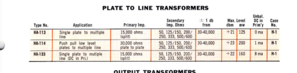
UTC HA-114
Unbalanced DC in primary: 1mA
Max. level: +23dBm, 200mW
Unbalanced DC in primary: 1mA
Max. level: +23dBm, 200mW
So those are NOT output transformers proper, .meaning use with speakers, only "line out" type, very different.
exactly, they are for line level output circuits.
In the first post I mentioned the impedance ratio, the secondary 600 ohm impedance is typical of vintage transformers for this application.
When I look at modern transformer datasheet made by Sowter for example, they specify the maximum primary DC current in each winding. This makes it a lot clearer what output stage they can be used for.
From my understanding "max unbalanced dc in primary" only tells how much the output tubes can be mismatched without compromising low frequency.
It doesn't actually tell how much current can flow in the primary wire before meltdown.
This means that the tube used must be well selected for ppUnbalanced DC in primary: 1mA
If you measure the Rdc and it is same for both semi- primary ( as seems you wrote) with reasonable low Rp tube and good muThis transformer is a UTC HA-114, I have attached an image of the datasheet.
Then a good selection of tube and when you have built the circuit check the voltage at the ends of primary if it is 0 volt the current is well balanced inside the trafo an no risk of saturation
Walter
In my opinion not more than 10 mAIt doesn't actually tell how much current can flow in the primary wire before meltdown.
Walter
No problem with selecting a tube with balanced sections.This means that the tube used must be well selected for pp
Since low currents are involved, for a cathode bias output stage a potentiometer can be added to fine tune the balance.
How do you come to this conclusion ?In my opinion not more than 10 mA
I would really like to find out a way to calculate this.
Alternatively there could be a way to make measurements with the circuit all built, to ensure the transformer is not under stress and heating up internally ?
I mean also a dynamic selection not only staticNo problem with selecting a tube with balanced sections.
About the current, It is my opinion but I am confident about the value
10 mA on 720 ohm are 72 mW x2 = 144 mW
This is the power that it dissipate in dc
Then for ac it is another film
Walter
Last edited:
A 10% imbalance is usually acceptable in good PP OPT's. So for 1mA you get 10mA as a typical idle current. I think you have a OPT usable for high Z headphones. 600R headphones and the driver tubes would be line stage types that run 10mA class A maybe balanced circuit ... just a guess. But you are starting with some good info on that tranny. Good luck finding an equation to assess an totally unknown tranny. It's a perennial question.
Yes, 10/10. So you could have 9/10 or 10/11 for a 10% imbalance. My solution to unknown trannies is to avoid acquiring them or dump them. I don't like having underutilized or components with questionable reliability in my creations. Scrap value is nil. A 10K/8R 10W tranny is not the same as a 5K/4R 10W tranny or they would be labeled as such.
pardon my ignorance. how do you come to the conclusion144 mW is a safe figure ?10 mA on 720 ohm are 72 mW x2 = 144 mW
I have another transformer with dc resistance 438 ohm on each primary side. how can I apply the same concept ?
Last edited:
I'm thinking an output tube like 12AU7, 12BH7, 6SN7, 6CG7 could be a good candidateA 10% imbalance is usually acceptable in good PP OPT's. So for 1mA you get 10mA as a typical idle current. I think you have a OPT usable for high Z headphones. 600R headphones and the driver tubes would be line stage types that run 10mA class A maybe balanced circuit ... just a guess. But you are starting with some good info on that tranny. Good luck finding an equation to assess an totally unknown tranny. It's a perennial question.
I did only a calculation about the dc power dissipated.pardon my ignorance. how do you come to the conclusion144 mW is a safe figure ?
But I am sure that it is inside the safe area.
About tubes you need to use one with a Rp at 1/3 - 1/4 of the value of the half primary value of trafo to get a good bass response
With 12AU7, 12BH7, 6SN7 you have a low gain of tube that must be divided 7 ( theory) so you will have around 20/7 times
And using these tube, the bias current must be around 7-10 mA to get a working point in a good region of the curves.
6FQ7 has a Rp too high, in my opinion.
With ecc88 you can get around 33/7 times and it has a reasonable low Rp
Walter
- Home
- Amplifiers
- Tubes / Valves
- Output transformer max primary current