Hello,
Once again I have decided to throw my hat into the Ring known as InDIYana (Midwest Audio Club annual get together), and as usual, I don't really know what I am doing.
^The most important part of that is, my Wife has once agreed to drive 6 hours/300 miles across an International border to attend with me.
I must be thicker than the average bear, because I don't think I really understand all the rules, but Ben has said my plans for a coaxial tweeter/mid and pair of midwoofer isobaric style meet the theme criterion, so here we are.
Drivers are,
2x,
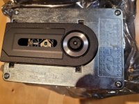
Sica 6,5 C 1,5 CP
Coaxial unit for HiFi and Studio Monitor
Code: Z004102
Nominal overall diameter: 6.5″
Nominal voice coil diameter: LF 1.5″ / HF 1″
Magnet material: LF Ferrite / HF Neodymium
Basket material: Aluminium Die-Cast
Power: 240 W
Sensitivity: LF 91.0 dB / HF 93.9 dB
Frequency range: 55-18000 Hz
4x,
Sica 6,5 H 1,5 CP
Hi-Fi / Studio Monitor
Code: Z004100
Nominal overall diameter: 6.5″
Nominal voice coil diameter: 1.5″
Magnet material: Ferrite
Basket material: Aluminium Die-Cast
Power: 240 W
Sensitivity: 89.4 dB
Frequency range: 40-4500 Hz
There is an overall plan (more of an outline) in my head for what I want to do, but most of the specifics are still to be worked out.
Baffle is to be 1.5" bamboo made from a stock shelf item at a local building centre, edges are going to get a 1.5" roundover, so with the woofers frame being almost 7", that gives me a baffle width of 10-11 inches'ish. Coax and woofer share the same basket dimensions. Coax will be mounted as close to the top of the baffle as possible with no edge treatment on the top edge.
Distance between woofer and coax will be whatever it needs to be. Not sure how much to chamfer backs of the baffle around the woofer for enough breathing room, nor how big the enclosure behind the midwoofer needs to be to attach the second isobaric woofer behind it. These two things will have a lot to do with overall enclosure height, and overall box dimensions cannot be determined until I work these two things out.
Box material will be a semi normal 3/4" Baltic birch box with separate chambers for coax and woofer sections, one solid brace between. Two removable panels on the back to get into box for XO, wiring, port tuning etc.. Veneer sides, either bamboo, walnut or cherry, not sure yet. No translam this year, too expensive, too time consuming and mostly too heavy,
Once I decide on how much the drivers need to breathe, then I can build the isobaric back chamber, then I can design a box around what those need to be. Not very good at planning all this out in advance, just take one step at a time and see where I end up.
My understanding of one of the major drawbacks to Coaxial speakers is intermodulation distortion caused by the woofer surrounding the tweeter, so I hope can limit its extension by crossing it over to the midwoofers beneath it around 400-600Hz. This will be instead of running the woofer coax full range (no high pass) and using the isobaric midwoofers as the .5 in a 2.5. I know sensitivity will take a big hit with this plan, but it's the plan.
Let the building commence,
(This is an isobaric build for sake of an isobaric build theme show and tell get together, please refrain from commenting on the general merits of isobaric designs)


 Thread title changed at member's request.