Hello,
Once again I have decided to throw my hat into the Ring known as InDIYana (Midwest Audio Club annual get together), and as usual, I don't really know what I am doing.
^The most important part of that is, my Wife has once agreed to drive 6 hours/300 miles across an International border to attend with me.

I must be thicker than the average bear, because I don't think I really understand all the rules, but Ben has said my plans for a coaxial tweeter/mid and pair of midwoofer isobaric style meet the theme criterion, so here we are.
Drivers are,
2x,
Sica 6,5 C 1,5 CP
Coaxial unit for HiFi and Studio Monitor
Code: Z004102
Nominal overall diameter: 6.5″
Nominal voice coil diameter: LF 1.5″ / HF 1″
Magnet material: LF Ferrite / HF Neodymium
Basket material: Aluminium Die-Cast
Power: 240 W
Sensitivity: LF 91.0 dB / HF 93.9 dB
Frequency range: 55-18000 Hz
4x,
Sica 6,5 H 1,5 CP
Hi-Fi / Studio Monitor
Code: Z004100
Nominal overall diameter: 6.5″
Nominal voice coil diameter: 1.5″
Magnet material: Ferrite
Basket material: Aluminium Die-Cast
Power: 240 W
Sensitivity: 89.4 dB
Frequency range: 40-4500 Hz
There is an overall plan (more of an outline) in my head for what I want to do, but most of the specifics are still to be worked out.
Baffle is to be 1.5" bamboo made from a stock shelf item at a local building centre, edges are going to get a 1.5" roundover, so with the woofers frame being almost 7", that gives me a baffle width of 10-11 inches'ish. Coax and woofer share the same basket dimensions. Coax will be mounted as close to the top of the baffle as possible with no edge treatment on the top edge.
Distance between woofer and coax will be whatever it needs to be. Not sure how much to chamfer backs of the baffle around the woofer for enough breathing room, nor how big the enclosure behind the midwoofer needs to be to attach the second isobaric woofer behind it. These two things will have a lot to do with overall enclosure height, and overall box dimensions cannot be determined until I work these two things out.
Box material will be a semi normal 3/4" Baltic birch box with separate chambers for coax and woofer sections, one solid brace between. Two removable panels on the back to get into box for XO, wiring, port tuning etc.. Veneer sides, either bamboo, walnut or cherry, not sure yet. No translam this year, too expensive, too time consuming and mostly too heavy,
Once I decide on how much the drivers need to breathe, then I can build the isobaric back chamber, then I can design a box around what those need to be. Not very good at planning all this out in advance, just take one step at a time and see where I end up.
My understanding of one of the major drawbacks to Coaxial speakers is intermodulation distortion caused by the woofer surrounding the tweeter, so I hope can limit its extension by crossing it over to the midwoofers beneath it around 400-600Hz. This will be instead of running the woofer coax full range (no high pass) and using the isobaric midwoofers as the .5 in a 2.5. I know sensitivity will take a big hit with this plan, but it's the plan.
Let the building commence,
(This is an isobaric build for sake of an isobaric build theme show and tell get together, please refrain from commenting on the general merits of isobaric designs)


Once again I have decided to throw my hat into the Ring known as InDIYana (Midwest Audio Club annual get together), and as usual, I don't really know what I am doing.
^The most important part of that is, my Wife has once agreed to drive 6 hours/300 miles across an International border to attend with me.
I must be thicker than the average bear, because I don't think I really understand all the rules, but Ben has said my plans for a coaxial tweeter/mid and pair of midwoofer isobaric style meet the theme criterion, so here we are.
Drivers are,
2x,
Sica 6,5 C 1,5 CP
Coaxial unit for HiFi and Studio Monitor
Code: Z004102
Nominal overall diameter: 6.5″
Nominal voice coil diameter: LF 1.5″ / HF 1″
Magnet material: LF Ferrite / HF Neodymium
Basket material: Aluminium Die-Cast
Power: 240 W
Sensitivity: LF 91.0 dB / HF 93.9 dB
Frequency range: 55-18000 Hz
4x,
Sica 6,5 H 1,5 CP
Hi-Fi / Studio Monitor
Code: Z004100
Nominal overall diameter: 6.5″
Nominal voice coil diameter: 1.5″
Magnet material: Ferrite
Basket material: Aluminium Die-Cast
Power: 240 W
Sensitivity: 89.4 dB
Frequency range: 40-4500 Hz
There is an overall plan (more of an outline) in my head for what I want to do, but most of the specifics are still to be worked out.
Baffle is to be 1.5" bamboo made from a stock shelf item at a local building centre, edges are going to get a 1.5" roundover, so with the woofers frame being almost 7", that gives me a baffle width of 10-11 inches'ish. Coax and woofer share the same basket dimensions. Coax will be mounted as close to the top of the baffle as possible with no edge treatment on the top edge.
Distance between woofer and coax will be whatever it needs to be. Not sure how much to chamfer backs of the baffle around the woofer for enough breathing room, nor how big the enclosure behind the midwoofer needs to be to attach the second isobaric woofer behind it. These two things will have a lot to do with overall enclosure height, and overall box dimensions cannot be determined until I work these two things out.
Box material will be a semi normal 3/4" Baltic birch box with separate chambers for coax and woofer sections, one solid brace between. Two removable panels on the back to get into box for XO, wiring, port tuning etc.. Veneer sides, either bamboo, walnut or cherry, not sure yet. No translam this year, too expensive, too time consuming and mostly too heavy,
Once I decide on how much the drivers need to breathe, then I can build the isobaric back chamber, then I can design a box around what those need to be. Not very good at planning all this out in advance, just take one step at a time and see where I end up.
My understanding of one of the major drawbacks to Coaxial speakers is intermodulation distortion caused by the woofer surrounding the tweeter, so I hope can limit its extension by crossing it over to the midwoofers beneath it around 400-600Hz. This will be instead of running the woofer coax full range (no high pass) and using the isobaric midwoofers as the .5 in a 2.5. I know sensitivity will take a big hit with this plan, but it's the plan.
Let the building commence,
(This is an isobaric build for sake of an isobaric build theme show and tell get together, please refrain from commenting on the general merits of isobaric designs)

First things first, I need to decide how to mount the "inside" woofer, what that is going to look like and how much space it will take up so I can figure out an enclosure size for this project.
Make a sample 1.5" baffle and mount a woofer in it to see what the back of it will look like, then see how much back bevel to give the front woofer so it can "breathe".
First attempt was with a 45º chamfer, but that seemed to generate too big an opening in the 1.5" thick baffle I plan on using, so I tried again with a 30º degree chamfer bit, and that seemed just right.
Now that I know what that looks like, I can make an enclosure that fits behind the front woofer and that the rear woofer can attach to. Just started with some circles 2" bigger than the baffles woofer back bevel opening, cut the same basket clearance hole in them, rebate for the rear woofer to "sit" into the chamber, and then bevel the end that mates to the baffle it to match the bevel on the back of the baffle. Writing this seems so straight forward, yet I spent hours thinking about how to go about this and changed tack a few times as I was going about it.
With the rear woofer mounts done, I can plan for an enclosure...
Enclosure,
Normally I don't worry about driver displacement in my enclosures too much because I am frequently using 1.5" thick baffles, and by the time I chamfer the back of the baffle to let the woofer breathe, the space "carved out" of the baffle is about what the driver displaces. This time, with the cylinder behind the front woofer, I needed to know what the displacement of that cylinder was and then add bit for the 2nd woofer before figuring out enclosure size. Cylinder is 8-5/8" dia x 2-1/8" thick, or about 2 liters displacement, going to guess under a liter displacement for the 2nd woofer. Before I set out to actually build the iso woofer adapter, I didn't really have an idea what volume it would take up, turns out, in the end, wasn't as big as I thought it might be.
Decided to measure all four woofers raw out of the box, and then after running them for 30 minutes high excursion at 30 hz.


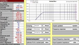
Then run some sims with the three sets of data,


Data not shown for Unibox, 10 watts input power, 2 drive units in parallel, compound, no external components
Going to shoot for 20 liters for woofer enclosure before all deductions like port tube, XO, 2nd woofer, etc.
Time to cut some plywood...
Normally I don't worry about driver displacement in my enclosures too much because I am frequently using 1.5" thick baffles, and by the time I chamfer the back of the baffle to let the woofer breathe, the space "carved out" of the baffle is about what the driver displaces. This time, with the cylinder behind the front woofer, I needed to know what the displacement of that cylinder was and then add bit for the 2nd woofer before figuring out enclosure size. Cylinder is 8-5/8" dia x 2-1/8" thick, or about 2 liters displacement, going to guess under a liter displacement for the 2nd woofer. Before I set out to actually build the iso woofer adapter, I didn't really have an idea what volume it would take up, turns out, in the end, wasn't as big as I thought it might be.
Decided to measure all four woofers raw out of the box, and then after running them for 30 minutes high excursion at 30 hz.
Then run some sims with the three sets of data,
Data not shown for Unibox, 10 watts input power, 2 drive units in parallel, compound, no external components
Going to shoot for 20 liters for woofer enclosure before all deductions like port tube, XO, 2nd woofer, etc.
Time to cut some plywood...
Attachments
It has been a few days since I have posted an update on my InDIYana Iso build, lots of separate parts are being worked on at the same time, but not enough in one area to bother posting about.
The cabinet is starting to come together. It is made from 3/4" Baltic Birch and I am using my standard lock rebate joint to connect the top/middle/bottom to the sides. I just use a 1/8" full kerf 24 tooth flat top grind rip blade as a 1/8" dado blade to made a 1/8"x1/8" grove in the sides and to leave a 1/8"x1/8" tab on the sides to making gluing up easier, things squirm around less. I also break down the glue up, by only gluing one side at a time. It only takes 20 minutes in the clamps, so do one half of one, go do the first half of the other, go back, etc. Makes for less stress if you only have to worry about one side at a time. The grooves for the top and bottom were deliberately made about 1/16" in from the edge of the top and bottom to be flush trimmed off.
Looks like the veneer for this project is going to be walnut, but I don't want to veneer the back, but I also didn't want the rear ply edge showing, and I hate iron on edge banding. Decided to make some solid walnut edging and attach it with the CMT ply edge set.
Lastly, you can see an additional groove all the way around the the inside on the rear of the box, that will be for the bits that the removable back attach to. More on that later...
P.S. Still working on a name for this project...
Part 5,
Today's update couldn't be more boring, it is about the back of the speaker cabinet.
Normally, it would consist of, "I glued the back on".
By why do something so simple, when there are many ways to make it as complicated as possible?
As per my normal, I went the second route.
The back needs to be removable for a couple of reasons, mainly to get the second isobaric woofer installed and wired. Also helps with installing the crossover and port tuning. Simple way would be to use wood screws to install the back, but I went for threaded inserts and furniture screws to hold the back on.
You will have seen the 1/8"x1/8" groove all the way around the inside rear of the cabinet, that was so I could glue in the bits that would make the rear frame the back would attach to.
Furniture screws have a shallow 11/16" dia countersink in the back panels with a 1/4" through hole internally chamfered.
Holes from back panels were transfered to back frame by drilling through back panels, centered with shims.
In order to make sure 1/4" holes were concentrically enlarged to 7/16" for threaded inserts without wandering, a step bit was used to get to the correct diameter, followed by a 7/16" normal drill bit to through drill full depth, holes were also internally chamfered so threaded inserts would sit slightly below the surface.
Took a few iterations to come up with a rear terminal cup bass reflex port layout. Originally in my mind I was going to make a fancy recessed built in terminal cup, but realized wires from XO to rear terminals would have to be attached before the back went on (the wires would be long) since there was no access from the front woofer cut out. Ditched that idea and went with pedestrian 3" diameter premade cups. These would allow me to pass the XO wire out the back with just a little bit of slack to attach to the terminal cup before securing. Terminal cups are attached with #6 button head socket cap screws through to Tee Nuts. Everyone hates Tee-Nuts and has a horror story about them popping off. Securing them with a pair of #4 1/2" screws should make sure that never happens.
I did mix up some 30 minute epoxy and spread alot of it around the large threaded inserts that flowed down into and around their threads, I don't think they will be going anywhere.
Internal block for bass reflex pipe to attach to was glued on, drilled out, flush trimmed to pipe and externally rounded over with a 1" roundover bit.
I can make anything complicated.
Baffle is next...
Time for another tedious update on my Sica iso speaker build,
My plan to use a prefab 1-1/2" bamboo shelf for a baffle fell through when once I started to machine it, the interior was full of random voids. I had already picked up bamboo veneer for the sides as well.
Crap.
What can I do next on short notice that isn't going to cost more money? I have on hand some split live edge walnut and a half sheet of left over Baltic Birch? Translam front and shop made walnut veneer for the sides!
Pics of gluing up translam baffle, laying out baffle, routing in for drivers, attaching second isobaric woofer chamber/holder, installing M4 threaded inserts into the baffle to hold drivers, lapping the box flat on giant sanding block before gluing on baffle, some dowels here and there to things align during glue up so they don't slide around and finally using a solid carbide spiral upcut bit to flush trim the baffle to the box sides.
Next up, Walnut Veneer...
Very nice project and documentation!
Will you make internal roundovers for the reflex port? I suggest to do so, it greatly reduces port chuffing.
A bit violent, however - spanish for contract killer ...
Will you make internal roundovers for the reflex port? I suggest to do so, it greatly reduces port chuffing.
"Sicario" perhaps?Still working on a name
A bit violent, however - spanish for contract killer ...
Work on the as of yet unnamed InDIYana 2024 isobaric project continues,
To go back a bit, the baffle was to be Bamboo, but the Bamboo shelf I bought to use as a baffle was riddled with random voids, so I switched to a Translam baffle. The sides were going to be Bamboo veneer, but I thought it looked too busy with the Translam front, so I decided to use some walnut I had kicking around to cover the Baltic Birch plywood. Plans change.
Last time I was at my favorite local sawmill, I picked up a bunch of random 6/4 live edge walnut boards to add to the stash for future use. Just as an aside, I have a great disfondness for epoxy encased live edge anything so saving boards from such a fate seems like a good deed right off the bat.
Pics of the board as retrieved from the basement, it didn't take much to make the split from the top and bottom connect and separate the board into two boards.
Boards were cut to length and resawn once for the first book match.
Once glued up, they were resawn again to make book matched book matched panels (bookmatched^2?).
Ran them all through the drum sander.
Monkeyed around with the layout, decided to make it so the left sides on both are the same and the rights on both are the same, as opposed to the left/right of each speaker being the same (if that makes sense).
I like to use a j-roller to spread out large amounts of glue, goes quicker and more evenly.
Used a torsion box for a ghetto cold press.
As per normal, trimmed things with a solid spiral flush trim bit. I prefer to do this in a table as opposed to free hand, I can easily limit the depth of cut per pass with the fence (usually just 1/8" max trim per pass) and things don't get away from my like they can free hand with a hand held router.
Used a Freud 1.5" roundover bit on the vertical front edges of the box. Took about 4 passes to full depth to be safe.
I was concerned how the 3/32" veneer would look at the top and bottom framing the translam, but I like how the look turned out.
Couple pics of the boxes all sanded and also showing the removable backs without port or terminal cups.
Next up, Applying finish....
really nice build could I ask a couple questions . so do you oversize all your panels by the thickness of the blade in each direction then cut a shallower cut the same thickness to leave your rebate. I mean to ask what's your process for measuring /determinating the size of the panels I work in mm might be why it's not soaking in . and is it mainly for alignment in glue up ? also how fast do you run that roundover bit pls I have one similar and haven't tried it yet . finally am interested in picking up one of those dewalt routers dust the dust extraction work well on that model ? thanks very much James
so do you oversize all your panels by the thickness of the blade in each direction then cut a shallower cut the same thickness to leave your rebate.
really nice build could I ask a couple questions . so do you oversize all your panels by the thickness of the blade in each direction then cut a shallower cut the same thickness to leave your rebate. I mean to ask what's your process for measuring /determinating the size of the panels I work in mm might be why it's not soaking in . and is it mainly for alignment in glue up ? also how fast do you run that roundover bit pls I have one similar and haven't tried it yet . finally am interested in picking up one of those dewalt routers dust the dust extraction work well on that model ? thanks very much James
Horizontal panels are oversized by the width of the blade to account for the "tongue", and the "tongue" is bladewidth x bladewidth in size. Groove is slightly deeper the blade width to allow the glue to have somewhere to go and flow. I'm in Canada, which is supposed to be metric, but all our tooling is still in SAE/Imperial, standard blade width is 1/8" which makes adding 1/4" to panel width pretty easy. I have also been doing fractional math in my head for 40 years, so it is super simple for me.
Dewalt DW621 is in my not so humble opinion the best "medium" sized plunge router on the market, perfect for the speaker builder, dust collection works very well, plunge mechanism is smooth, depth rod works well for setting depth of cut and depth dial works great for making incrementally deeper cuts. (BTW, my day job has been selling tools for 25 years, I am quite versed in most brands).
- Home
- Loudspeakers
- Multi-Way
- David's InDIYana 2024 "Inner Sanctum" theme Build, Coax w/Isobaric Midwoofers