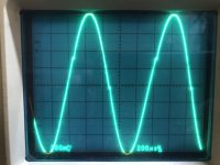
I’m a little stumped on this so I’m looking for help. I wired up an Engl style preamp on the bench to mess around with this weekend, just 4 stages with 2 12ax7. Something sounded really unpleasant at all gain levels so I started to probe around and noticed these weird notches in the signal on the plate of the first stage. The positive one seems to correspond to the voltage level at which the next stages grid starts to conduct; the negative side notch mirrors it.
Now, the notch isn’t present on my guitar or the signal generator I’m using. it’s not present at the grid of the first stage at any gain or signal level. It matches the input frequency and while there is a lot of high frequency noise in my house this particular pattern isn’t there with no signal applied. It sort of fades in as the gain knob is turned up which is part of why I think it’s related to grid current. I added a big 470k grid stopper right at the socket (note that there is always a 100k in series anyway) and the notches got smaller but never really disappeared at high gain when viewing the first stage anode signal. And obviously it’s still there at the grid of stage 2. I also pulled all the cathode bypass caps. I thought blocking distortion but the DC level at the grid isn’t going negative much at all in overdrive conditions. And frankly, I’ve built a lot of tube preamps and I’ve never seen notches like this.
Oh, and oscillation is a possibility. The circuit isn’t fully stable at all gains and guitar volumes. But when it does howl I can move wires and affect frequency but no wire manipulation affects the notches in any way. They are there all the time.
I know the Engl schematics are famously incomplete but I figured I’d start with the basics and tweak it myself. Here’s a reference file, all I have is from the input jack to the tone stack and I’ve omitted the switching around R10 and the bright cap.
Attachments
I wired up an Engl style preamp on the bench to mess around with this weekend, just 4 stages with 2 12ax7.
"Just" 4 stages? 😱
Math says possible gain is 50*50*50*50 😱
Do the Math.
Even removing cathode caps and adding attenuators, that is monster gain.
Something sounded really unpleasant at all gain levels so I started to probe around and noticed these weird notches in the signal on the plate of the first stage. The positive one seems to correspond to the voltage level at which the next stages grid starts to conduct; the negative side notch mirrors it.
Those notches are minuscule, practically inaudible.
Maybe you have a problem but it's not there.
In any case, often weird non clipping waveforms appear because of poor grounding.
Non zero ohm, non zero inductance "real world" ground (be it chassis, wire or track) "mixes" signals the wrong way, signals from unrelated stages (but which share return paths) and create weird waveforms or instability.
That's why new designs take "x" time ... then debugging takes many times more.
😫😫😫
"Just" 4 stages? 😱
By that I meant no Fx loop, phase inverter, output stage, etc. just the preamp.
But I’ll look at grounding. I’m sure it could be better as I’m using a piece of bus wire for most of it but I also have some alligator clips in there too. I‘ll replace that all with soldered wire and see if things improve. Thanks.