Allen and Heath Zed6 fx no power

I have two dead Allen and Heath Zed6 mixers.

Mixer 1 is a zed6fx
Mixer 2 is a zed6

I was listening to music on mixer 1 when it lost power. No lights. Switched off and on. Nothing. Dead.

I checked continuity of the mains cable and fuse and checked mains was coming out of the mains cable into the 3-pin socket on the mixer.

I opened the mixer followed the volts to an internal pcb mounted fuse and ordered a replacement.

I replaced the internal fuse.

Switched the mixer on. Nothing. No lights. Dead.

I swapped it with mixer 2.

For several weekends, I would listen to music through it for a couple of hours until a week ago it lost power. Exactly the same as the first mixer1.

What is killing my mixers?
How do I check this?
How do I fix this?
Does anyone have a clear pdf of the process circuit diagram?

Power MOSFET heatsink

For mounting of power MOSFET on heatsink of Aleph 5 clone on 2 separate heatsink, is there any preference to:

1) mount Q6 - Q8 on a heat sink, and Q18 - Q20 on another heat sink; or

2) mount Q6, Q7, Q18, Q19 on one heatsink, and the rest on the other.

I am asking this from the point of thermal consistency, and if there are other considerations such as interference etc.

Thank you

IMG_9642.jpeg

For Sale WBT binding post and RCA

Verry good speaker binding post from German hiend conectors maker.Pkus one pair of ther verry good rca conectors.Used but full functional .Plese look on the pictures.Price 150 euro including shipping inside EU!

Attachments

  • 20240427_090737.jpg
    20240427_090737.jpg
    1.1 MB · Views: 184
  • 20240427_090839.jpg
    20240427_090839.jpg
    1 MB · Views: 185
  • 20240427_090746.jpg
    20240427_090746.jpg
    802.7 KB · Views: 153
  • 20240427_090750.jpg
    20240427_090750.jpg
    923.7 KB · Views: 189

Shielding circuits / transformers (another one) 🙄

Hello again!
Being thinking too much, I ask myself how to come by with troubles with EMI etc.

Firstly, I had to tuck my UFSP phono pre as far away as possible to get it out of the range of the other trannies (preamp, poweramp, computer). Would it help and be sensible to put the boards into a shielding case of iron inside the aluminium-chassis?

And secondly, I am currently working on a tight build (the holy grail , mine is at #548), where the PSU will be stacked and placed inside the amp, and try to make up a shielding solution… so I’m thinking about building something like a shielding-case inside the chassis.
Should the rectifier be included in the shield? (Would this help?)
Same with the CRC block…

Opinion on three way crossover - and path delay

Hello! I'm restoring and upgrading an old pair of 3-way speakers. I decided to make a crossover upgrade as well since I was at it. The old one didn't sound very well. I measured the drivers and loaded the data on Xsim.

It's an old pair of Namco NSU-770 (made by Panasonic in the 70s I guess...)
It's a 12" woofer paper woofer, 2,5" paper dome midrange, 1" aluminum tweeter.

This is my try at it but it's my first time doing a 3-way.

The FR and impedance graph look pretty okay to me but when I was setting the delay the simulated curve didn't overlap perfectly with the measured one. I did my best to match as closely as possible the measured tweeter + midrange response with the simulated one.

The woofer's FR looks pretty odd, there's a big hole at around 700Hz. I guess I'll have to live with this. The phase seems okay, reversing the midrange compared to how it's now leads to a weird FR.

Do you think this design can be improved in any way?

Project files are attached.

Thank you!
1713617436866.png

Attachments

  • Locked
For Sale Focusrite Scarlett 18i8 (2nd gen) audio interface

SOLD

Selling an immaculate Focusrite Scarlett 18i8 (2nd gen) audio interface; includes original packaging and accessories


  • 2x XLR / TRS / TS combo (mic / line / inst) inputs
  • 2x XLR / TRS combo (mic / line) inputs
  • 4x TRS line inputs
  • 2x TRS line outputs
  • ADAT input (8ch @ 44.1/48, 4ch @ 88.2/96)
  • S/PDIF input & output
  • 2x headphone outputs

Original power supply and USB cable included.

Would prefer to ship within EU (25eu); open to shipping elsewhere as well, pending checking costs - customs and any other fees are the buyer's responsibility.

Looking to get ~220eu 200eu, but i'm open to offers 👍

Payment via Paypal, Mobilepay or bank transfer.

Attachments

  • 01.jpg
    01.jpg
    201.6 KB · Views: 65
  • 02.jpg
    02.jpg
    233.6 KB · Views: 79
  • 03.jpg
    03.jpg
    171 KB · Views: 71
  • 04.jpg
    04.jpg
    284.3 KB · Views: 73

W8-2145 lying around - building something fun with them? desktop use?

I have a pair of W8 2145 lying around and wonder what to do with them.

Open baffle is out of the question and I already have a pair of BIBs doing their job wonderfully as "allround speakers" with W8 1772's in them.
Thanks to @Scottmoose I also already have a pair of desktop TL speakers. So all my audio-needs are taken care of.

Just for the fun of it, I thought about maybe building "very small" desktop bass-reflex speakers so I could have the 8" speakers blasting into my face more or less directly.
What else could bedone? 😀

Bluetooth Amp no longer connecting

Hi,
Hope you're well.

I received this amp (image attached) as a gift a few years ago and it's worked like a charm.
However recently the sound started stuttering when connecting to my computer, but not with other devices. I tried these steps but none helped: Login to view embedded media Now my computer is no longer connecting to it (image attached).
The last time it did connect, it was asking for a password but I don't remember it.
I've tried all the usual steps to reset drivers, uninstall reinstall etc from the computer side, but nothing works.
I've clicked the reset button on the amp and that didn't do anything.

Any advice would be really appreciated.
Kind regards,
Yogi

Attachments

  • 20240505_094907.jpg
    20240505_094907.jpg
    361.5 KB · Views: 70
  • 20240505_100815.jpg
    20240505_100815.jpg
    363.3 KB · Views: 67

Too bad this got out of fashion… sort of

I just came across the system 1 from nakamichi, I must say I quite like it.

As stated in the title, too bad nobody seems to go down this rabbit-hole anymore.

I mean, that’s techy product design, and the chassis‘ concepts are quite smart, allowing both an on-desk or in-rack placemt without the huge depth of yesterday’s gear. (Ok, nowadays it’s all pocket-sized but hey!)

The Kartesianz vs The Denmark Devilz :)

Quality has a price , first the transducers in all their glory :

https://www.kartesian-acoustic.com/copie-de-monitoring-studio

Some graphs to seperate the good from the bad and ugly (danish rubber scandalettes) :

https://www.kartesian-acoustic.com/copie-de-vki

Study Them Well Or Go To Hell 🙂


ps .. anything you need for a good life : Login to view embedded media

Adcom GDA-700 DAC, help updating to modern parts

Yesterday I received a great condition Adcom GDA-700 DAC. My first experience with the PCM1702 chip, I like it! I have a Audio-GD R-1 NOS already and while it is pretty amazing, I've never felt like I completely vibed with it, mainly because the sound stage is so very in my face all the time. Now with the Adcom, I am hearing pretty much all the same detail but with a much more dispersed and pushed back soundstage. And for about third of the price, this is a win for me.

So I figure now that I have it, it would be worth it to tinker with OP amps and replace some parts since this guy is from 1995 😎.

The tools I own already:
  • Soldering iron
  • Good Rosin solder, solder wick
  • Decent Multimeter w/ clip and point leads
  • Cheap pcb holder
I should probably get a chip puller, can't think of anything else tool wise. I have good experience I believe since I have completed a BHC amp and various diy cables.

I figure the sound quality can only go up from here. Problem is I don't know/don't really understand how to choose replacement OP amps. I get the general principle but frying my new dac would really suck. I did some digging and found this post for modern OPA alternatives: https://www.diyaudio.com/community/threads/adcom-opamp-semiconductor-replacements.339904/

The ones in the GDA-700 are ADCOM 6AA 9439. According to the chart I can use OPA604 or AD711. I would love to use some sparkos SS3601 OPAs but I need to know if they aren't compatible.

Other than the OPAs, is it safe for me to order all new caps with matching uf/V ratings as the ones already installed? A quick search led me to these caps:

https://partsconnexion.com/products/elna-capacitor-10uf-35vdc-roa?_pos=1&_sid=c38316f85&_ss=r

The only schematic I found was pretty rough but still legible:

https://akdatabase.org/AKview/displayimage.php?album=20&pos=6

This is a big step for me but it's got me pretty stoked! Any and all advice is greatly welcome. Thank you for reading my first post here.

Photos below

IMG_20240504_171825.jpg IMG_20240504_171657.jpg

IMG_20240504_171354.jpg IMG_20240504_171438.jpg

First Time Crossover Advice And Help. Utilizing Xsim and I think I'm headed in the correct direction. I would like some expert eyes on it though.

I've been attempting to learn Xsim over the last several nights trying to work out a crossover for an upcoming project. I think I have a beginner grasp of what to do in regard to leveling out the frequency response, but I feel lost when it comes to keeping the phase in check. I also am unsure what my goal is for the impedance chart so any pointers there would also be of great help. Please let me know if I'm massively screwing something up with this 🙂 I have attached screenshots of the charts and wiring diagram and the project file.

Attachments

  • Crossover Frequency Respone Graph.jpg
    Crossover Frequency Respone Graph.jpg
    131.2 KB · Views: 155
  • Crossover Impedence Graph.jpg
    Crossover Impedence Graph.jpg
    133.4 KB · Views: 149
  • Crossover Wiring Diagram.jpg
    Crossover Wiring Diagram.jpg
    83.8 KB · Views: 148
  • Crossover .02.dxo
    Crossover .02.dxo
    81.6 KB · Views: 55

Rockford Fosgate RFP-2000 power amp

I was able to pick a set, Rockford Fosgate RFP-2000 ( Hafler JF2000 ) and the matching preamp the RF-200 for very little money, very good quality.

Can anyone comment on the design of the amp ?
32 mosfet transistors
2 42000uf 80V power capacitors
a few 5532 op amp in the motherboard, all Texas instruments

The only problem so far with the amp, is one side gets hotter than the other one.
Since the amp has so many output transistors, how do I know that all of them are working fine ?
Any idea the bias number for this amp ?

Attachments

  • RF2000 schematic.pdf
    RF2000 schematic.pdf
    305.7 KB · Views: 192
  • Audio magazine rf2000 review.pdf
    Audio magazine rf2000 review.pdf
    466 KB · Views: 186
  • IMG_0172.JPG
    IMG_0172.JPG
    511.9 KB · Views: 133
  • IMG_0174.JPG
    IMG_0174.JPG
    462.2 KB · Views: 122
  • IMG_0175.JPG
    IMG_0175.JPG
    537.7 KB · Views: 119
  • IMG_0176.JPG
    IMG_0176.JPG
    572.2 KB · Views: 112
  • IMG_0177.JPG
    IMG_0177.JPG
    487.2 KB · Views: 118
  • IMG_0178.JPG
    IMG_0178.JPG
    448.5 KB · Views: 109
  • IMG_0179.JPG
    IMG_0179.JPG
    498.7 KB · Views: 108
  • IMG_0180.JPG
    IMG_0180.JPG
    522.3 KB · Views: 128
  • IMG_0181.JPG
    IMG_0181.JPG
    493.9 KB · Views: 100
  • IMG_0182.JPG
    IMG_0182.JPG
    492.1 KB · Views: 94
  • IMG_0183.JPG
    IMG_0183.JPG
    475.6 KB · Views: 118

Chassis hardware thread for the Eric amps community

I wanted to share some designs that I have been working on towards a dedicated standalone chassis for the FFAxxxx series of amp modules

First up is a mounting plate for the FFA001 module. This one is designed to be 3D printed and can be fitted inside a chassis or into active speakers, including instrument amps

Single fan
1714471248910.png


Dual opposed fans
1714471356984.png


Fasteners are M3 with the thread printed into the mounting holes. For instrument amps, M3 threaded rods are needed or long bolts if you can find them. The module is fitted inverted with the PCB side up. A 5mm standoff should be placed over the holes, and this will hold the module down and provide a receptacle for a matching metal sheet as screening cover. This isolates the heatsink which is elec active and protects the module entirely

Still double minded about the standoffs. I might do a version without them and instead use 50mm metal ones. This one is for tomorrow to solve

The back of the mounting plate inlays the fans and has allocation for air filters. Mounted inside a narrow chassis, the dual fan version is optimised for air flow around the module components

This is my priority project, so will soon upload the STLs for more parts such as custom speaker terminals and panel inlays, as well as a chassis that makes provision for a tube linestage for this class D module. Hope the community finds the plate useful and guys, share your custom creations here too

Attachments

Technical Articles for Audio

Hi Folks,
I was working on a project and really needed to see a copy of the original Thiele-Small papers on modeling dynamic speaker drivers from 1961 (Thiele) and 1971 (Small). These were not easy to find in a free format as they are typically cited as J. Acoust. Engr. Soc. papers. But I eventually found them. Very nicely written and amazing how they are still used to this day. A lot of similarity with the solution to the classic forced damped harmonic oscillator equation of motion.


Anyhow, it gave me an idea that once I find stuff, and if you guys find anything of use, let's post here for others to share.

PDF's:

Here is the one by Thiele from 1961:
https://diyaudioprojects.com/Technical/Papers/Loudspeakers-in-Vented-Boxes-Part-I.pdf

Here is where I found a scanned copy of the classic 1971 paper by Small:
https://diyaudioprojects.com/Technical/Papers/Direct-Radiator-Loudspeaker-System-Analysis.pdf

A nice treatment of the equations from above by engineers at ScanSpeak and put into MathCad format:
https://www.scan-speak.dk/datasheet/tech/Scan-Speak_Technote01_TS-measurement.pdf

How to use LTspice to sim T-S:
https://www.micka.de/en/download/spice-tsp_en.pdf

Threads / Websites:

There is a thread in Multiway on using LTSpice to model Thiele-Small parameters for speakers:
https://www.diyaudio.com/community/threads/thiele-small-reloaded-with-ltspiceiv.166467/

Videos:

Nice tutorial on analyzing stability of feedback circuits using LTSpice:
Login to view embedded media
How to measure open loop gain in LTSpice:
Login to view embedded media
Perhaps the BEST lecture I have ever seen on solving damped harmonic oscillators - by Prof Walter Lewin (MIT):
Login to view embedded media
Prof Steve Brunton (U of Wash) also gives great explanations on damped harmonic oscillators (4 ways to solve):
Login to view embedded media Login to view embedded media

Identify parts for JL JX500/1D

Hi everyone. Today im fixing a JL audio jx500/1d amp. Someone try to fix It before me so It comes with fqp12p20 mosfet at the PS, i think maybe need aot460 like others JL amps.
On the other side the 2 diodes AND the 2 output mosfets aré missing.

Anyone have the parts numbers? I need to buy all, the 4 PS mosfets, the 2 rectifiers AND the 2 output mosfets.

Thanks

Attachments

  • IMG20240407194710.jpg
    IMG20240407194710.jpg
    273 KB · Views: 128
  • IMG20240407194243.jpg
    IMG20240407194243.jpg
    281.6 KB · Views: 142

ACP+ vs. Wayne's Linestage

Dear fellow builders,
I am struggling to describe the differences between my ACP+ and Wayne's Linestage Preamp. Using the same Mark Johnson VRDN LPS for both of them. I prefer the ACP+ for experimental electronic music but I am not sure why.. maybe because it has a deeper soundstage and the sounds are "flying" closer towards myself? Or maybe the ACP+ has slightly thicker bass. For acoustic music I prefer Wayne's Linestage. Does anyone have experienced both preamps and could help me with describing the differences? Thank you very much!

Kind regards,
Johannes

Unique design of the Endeavor-E3 speaker

I've recently heard a pair of speakers at an audio show named the Endeavor E3 from VonShweikert, and despite being a smaller pair of 3 way floor standing speakers, sounded phenomenal. Perhaps the best I've heard considering the size. Being an avid engineering enthusiast, I figured to try and de cypher some neat design choices that was used when designing this speaker, and I thought to maybe get some expert input from you all as well.
Two models available: standard and special edition.
Standard:
Dayton audio reference woofer RS180
Hivi L6 kevlar woofer
Scan Speak R2604 ring radiator tweeter

Special edition:
Dayton audio reference woofer RS180
Hivi L6 kevlar woofer
Scan Speak D3004 beryllium tweeter
Rear mounted Fountek Cd3.0 ribbon tweeter

Crossovers:
modified 4th-order linkwitz-riley with zobel conjugates to ensure correct phase and time alignment-with extremely wide horizontal and vertical off axis accuracy.
Frequency Response: 29Hz to 22kHz (+/-2dB)
Weight: 95 lbs per cabinet
Dimensions: 44" x 9" x 15" (HxWxD) Tapers down to 5" width at the back.

Enclosure design:
Here's where it gets creative. The bass is said to be loaded in a 4th order Butterworth modified "tuned" aperiodic vent design, critically damped to Q=0.7.
The midrange is said to be loaded in a tapered transmission line to avoid standing waves and rear reflections to ensure accurate midrange.
Total cabinet thickness: 2.75"

I'm genuinely interested in learning how such bass is achieved in such a small design. Modeling these drivers in software using just a normal vent means the enclosure must be 2-3 times the volume in order to achieve a -3 of 28hz.

Attachments

  • ENDEAVOR-SPECIAL-EDITION-4.jpg
    ENDEAVOR-SPECIAL-EDITION-4.jpg
    28 KB · Views: 164
  • EndeavorE3.png
    EndeavorE3.png
    714.9 KB · Views: 167

What USB sound card to use for frequency measurement?

Hi,

I was using Behringer UCA222 for frequency measurement, but recently learnt that it has poor channel separation. I verified by using a signal on left channel and connecting and amlifier/speaker on the right channel. I could hear the test signal from right channel😕, even though it was faint.

So, what better USB sound card do you guys suggest for frequency measurement?

Thanks in advance,
Warm Regards,
WA
  • Like
Reactions: ginetto61

Balanced XLR input/output from tube gear

I notice most tube gear has unbalanced connections and the one piece of tube gear I tested that did have balanced jacks in addition to unbalanced, performed much better better using the RCA/unbalanced. I noticed when I opened it up, the XLR jacks were connected to some small transformers which I assume are what converted them to "normal" signals for the pre-amp board.

I haven't really studied this in depth yet, but my limited understand is most tube gear is not natively easily adaptable to balanced cables and use these types of transformers to convert that type of balanced signal into something they can process? I know I have rarely seen any tube schematics showing balanced connections.

Thanks in advance!

Cambridge Audio Minx Xi -Open Box - White

NOS Minx Xi from a dealer stock. Only head unit without accessories- (no USB antenna, remote, BT ). I checked basic amp, dac functions and it works fine. It won't connect to internet since it hasn't been updated and the system version is too old to bridge the gap with last issued software update. Cambridge Audio service recommended update via stick which would necessitate sending it to service dep. Any of you Diy mavens probably can make it work without the factory help.
I have no use for it and all the women in the house are too stupid to operate it even if I gifted it to one. Factory box and basic manual included and protective film on the face plate still present. $250
I will post pictures shortly

desoldering a double sided board

I have desoldered components off boards for about 4 years now however I am currently battling something I have never been able to do with my Hakko 808 or a soldering iron and that is desolder a component off a double sided board
I can get the solder off the opposite side of the component but the solder on the component solder is unaffected
I am trying to remove most of the through the hole caps

Is there a secret I dont know about and I hope it doesnt involve using a soldering iron and the hakko at the same time

Attachments

  • DSC07202.JPG
    DSC07202.JPG
    535.7 KB · Views: 122
  • DSC07203.JPG
    DSC07203.JPG
    509.9 KB · Views: 119

Picture Frame Speaker

I am in a situation where I have to built a very slim low profile picture frame speakers. It has to go on the wall, can’t go in wall. I found a speaker that checks all the boxes https://www.morelhifi.com/en/products/custom-integration/soundwall-30/soundwall-powerslim-series-42

I have a few dead ends I am hoping someone can clear up for me.

1. I am building a frame out of 1/2” high density MDF measuring H16” x W28” x D1.75”, which equates to .18 cu/ft

2. According to the speaker manufacturer the speaker must have .45 cu/ft

3. Can I built a port into a frame that can compensate for the difference of .27 cu/ft

4. The manufacturer also suggested stuffing the cabinet cavity with “pillow stuffing”. Will that help in any way?

Any suggestions are greatly appreciated.

Fostex T825 measurement help

Hi all,
I recently purchased a pair of Fostex T825 super tweeters, probably about 40 years old (originally from Fostex Laboratory series LS/3 monitors).
After a quick sweep the measurements lead me to believe one is faulty.

Does the lower trace show signs of a bad diaphragm? Or diaphragm not aligned/seated properly?
One sweep is with 4.7uF cap and another with 1.0uF cap.
Both measure 6.7ohms
Thankfully, the seller is willing to refund if I'm not satisfied.
Looking for some opinions before I bring them back.

Serial numbers are almost consecutive (11156, 11158).


Fostex T825 4.7uf comparison.jpg

Fostex T825 1.0uf comparison.jpg

Harman Kardon AVR265 sound issues

Hello everyone,
I have a Harman kardon avr 265 amplifier. I have a problem with obvious low sound on the left channel. There is no such problem on any of the other channels, only the left channel.
Recently, when I first turn on the device, the opening screen appears and freezes. When I press any button, it goes into stand-by mode and does not turn on. When I unplug it, plug it in and turn the device on again, it turns on and works without any problems.
Here's what I've tried so far regarding the sound problem in the left channel:
-different speakers. It didn't work.
-different cable. It didn't work.
-I tested it from different analog and digital inputs, it didn't work.
What do you think is the problem?
Thanks in advance to everyone who will help.

Noise out of a Princepton amp kit

Hi!

I'm building a Doctor Amp princeton kit and after building it completely I can't make it to work properly. The only sound I get out of the amp is a loud noise.

I've checked if I had positive feedback but the noise is still there after reversing primaries on the output transformer or removing the feedback wire.
This is the noise I'm getting Amp Noise

Any advice of what should I checked? any mistake I should have made? Any bad component?

Thanks!!!

What's the Best Way To Mount an Exciter?

Hello,

I've been experimenting with the Dayton Audio DAEX30HESF-4 exciter, and attaching it to the shiny side of erasable whiteboard. This results in spectacular sound through most of the audio spectrum. Highs in particular are amazing. However, in the bass, there is so much energy being released that the double stick tape cannot hold the exciter firmly enough against the board, and I get buzzing. The question is, how can I more firmly attach the exciter to the board? Should I try to attach it using the provided four mounting holes? And if so, how exactly do I do that? Or should I use a stronger adhesive? Or both? I welcome all suggestions!

XRK RTR TPA3255 Reference class D Amp GB2

Edit Dec 5. 2020: the GB is now taking preorders in my shop. I am including a free BTSB PCB with each order.

XRK RTR TPA3255 Reference class D Amp GB2

RTR TPA3255 Reference Class D amplifier | Etsy

This is the GB number 2 thread for the ready to run (RTR) TPA3255 reference Class D amp from this thread:
TPA3255 Reference Design Class D Amp GB

836851d1587609199-tpa3255-reference-design-class-amp-gb-67aa1113-6c7f-4ff0-91da-9f8655028f17-jpeg


The thread has a lot of details on the development process and build question and answers. A GB interest list will just get buried and lost in it so I decided to make a new thread as there seems to be some renewed interest now that Redjr has just released his masterpiece build using this amp. I have already received several requests for more RTR amps.

To make this viable for a manufactured amp from a California based assembly house, I will need a commitment for at least 20 amps from folks here. I will pledge to buy another dozen amps and we then get these professionally made using a pick and place machine with a genuine Mouser BOM.

As before, the default amp will be balanced input stereo BTL output. We now have the BTSB Buffer board to go with it which will provide the necessary conversion from SE inputs and gain to drive this amp effectively.

BTSB Buffer - SE/Bal to SE/Bal Buffer GB

The amp will be manufactured using 2mm thick pcb’s and 2oz copper and ENIG finish. Amp modules will be fully tested and come with a set of Molex connectors for audio in, speaker out, and PSU in. Pricing of the amp will be $277 each. The lead time may be up to 3 months, although I think it will go much faster this time since it is a second run and we have the kinks all worked out.

Edit Aug. 21, 2020: Special Promotion - Free BTSB Buffer PCB (TH or SMT) with your order of the RTR amp. A $23 value that allows this amp to be used with any source.

Please put your name, number of boards, and country down on the list below. Once we have 20, I will put a preorder listing on my shop for you to purchase.

Thanks,
X


Interest List:

Name / number of amps / country
____________________________

JohnDoe / 2 amps / USA

For Sale Peerless DA25BG08-06 pair, UK new unused

The first tweeters I bought were these as I thought they were quite benign for a beginner to work with. Great tweeter. I still have the first pair and I bought this 2nd pair thinking I'd use them for another project but it never happend (see my other gear for sale...I have eyes bigger than my belly when it comes to buying drivers!)

New from THLP in the original packaging.
£50 plus post

Attachments

  • IMG20240504125331.jpg
    IMG20240504125331.jpg
    170 KB · Views: 60
  • IMG20240504125255.jpg
    IMG20240504125255.jpg
    330.9 KB · Views: 59
  • IMG20240504125259.jpg
    IMG20240504125259.jpg
    249.2 KB · Views: 55
  • IMG20240504125303.jpg
    IMG20240504125303.jpg
    230.6 KB · Views: 54
  • IMG20240504125327.jpg
    IMG20240504125327.jpg
    156.8 KB · Views: 57

Just a simple analog multi channel volume controller?

Hi,

I thought it's just a simple question. I need a volume controller (just 1 rotary knob) to control 8 line level outputs with this "just 1 knob".

Although, it seems not that simple, as I can only find 1500 euro costing commercial devices, with 8 inputs and 8 outputs AND this just 1 knob. OK< they added a mute and a dim function and a set of buttons to select input and output.

What I woud love to have is build my own device / volume knob with 8 inputs at line level connectors, controlled by that knob to get 8 output line level connectors. Dim and mute switch woud be fine, but not a must.

WHY??

I am having a home studio Hybrid mixing desk (48 channels mixing desk combined with a Mac mini and analog converters) to mix multitracks (studio recordings) as a hobby and now want to go for Dolby Atmos (5.1.2 format) so 8 analog line level signals to 8 powered loudspeakers (Genelec 3010A).
To be able to control the volume I need 1 knob on all 8 channels but have not found a rotary knob that hods 8 "layers" if you get what I try to put in words.

SOLUTIONS?

The whole world is watching as "boxes" exist from various brands, but they start at 1500 euro upwards to 6000 euro just to put the volume a bit higher or lower, which I find a bit " h^&^213n(&623H^$^& " (not so nice word)......

Active crossover amplification class vs frequency

I am working on a 5 way active open baffle speaker with sealed sub bass unit.

I will use mini DSP for the crossover. Because the mini DSP has only 8 channels I may use a passive crossover between 2 of the drivers.

So I will need 4 stereo amplifiers. I don't have much experience with higher end amplifiers so I am curious what experiences people have.

For the subwoofer class D seems obvious but I have heard the opinion somewhere that class A for a sub sounds noticably better. Is class D really ideal for subs or just economical?

On the other end I have a small AMT as super tweeter above 9kHz. Does a tube amp make sense here or will you only notice the difference vs. class D or A/B in the midrange.

So basically I have two questions.

1. Are certain amplifier classes better suited for high, mid or low frequencies?
2. How does required amplifier wattage scale with frequency. If I have a 1000w amp for my sub, a 200w amp for my woofer would a 3watt tube amp suffice for my super tweeter?

RTR SSR Speaker Protection GB5

Hi Folks,
I have just run out of the last set of Ready to Run Solid State Relays (RTR SSR) speaker protection boards from GB4.

For those of you not familiar with this board, the original thread is here and you can see that it adds no distortion. There are now 400 units operating in the wild and no complaints or issues. This means 400 more speakers are practicing “safe music”.🙂

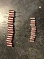
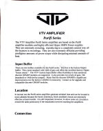
This seems like a useful product or audio “tool” that enthusiasts will continue to like to use. I would like to start a GB5 interest list. Jhofland was kind enough to redesign it to accommodate a newer voltage regulator since the ones we used on the previous units are no longer available. The older ones were special and able to handle voltages up to 150v and produced 15v out. We will have to use one that now has a maximum input of 35v. So this means that if your amp’s rails are more than 35v, you will need a separate lower voltage PSU or secondary winding for auxilary power circa 15vac secondary. Only 20mA is needed and you may be able to get away with wrapping some secondary magnet wire around your existing toroid to scavenge some extra low voltage power.

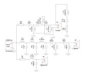
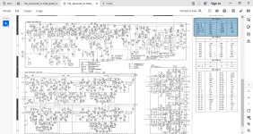
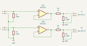
Here is the new schematic Rev 2.3:
1714738860197.jpeg


A small Low capacitance PSU bonus board (unpopulated) will be provided so you can use it to make DC from your trafo’s secondaries to allow anti-thump turn off.

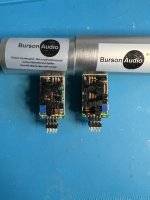
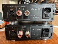
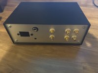
I still need to price it but I suspect prices have gone up on parts and will be circa $65ea once the GB is over. Those who pre order under the GB can get them for $50ea fully built and tested. As the name suggests - it is RTR. You just need to connect a PSU and connect to your amp output and speakers. A set of Molex KK 2 pin connector shell and crimp terminals will be provided.

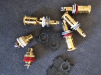
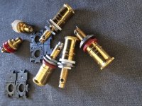
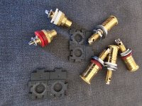
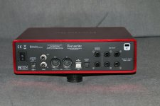
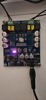
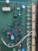
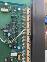
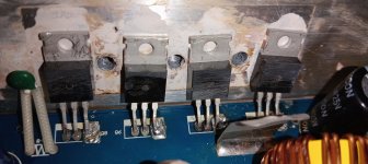
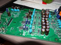
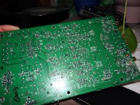
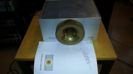
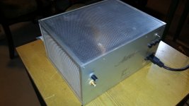
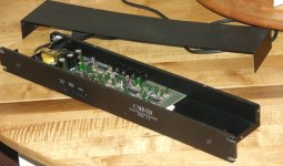
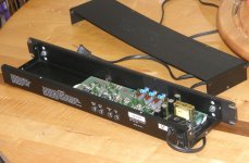
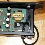
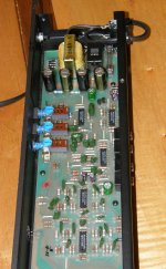
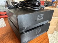
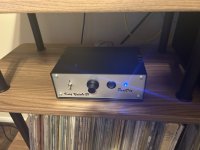
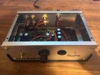
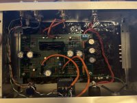
They will look very close to the units from GB4. We will still use the IXYS FDA215 optically isolated gate driver chip.

1668807687339.jpeg


Low capacitance PSU bonus board:
1668807994466.jpeg


Please add your name, number of units you are willing to pre-order, and country below.

To make this viable, we will need commitment from folks for at least 30 units.

For example:

Name / number of units / country
—————————————————-
xrk971 / 10 units / USA

A big thanks to Jhofland for making this superb design for a transparent and low distortion solid state speaker protection relay.

Update Dec 20, 2022: Great news - it turns out that the 150v capable voltage regulator used on the last GB is now available, so I am able to offer the identical unit as GB4 and there will not be a restriction on the input voltage to a 35v maximum anymore. You can basically power it with any reasonable main psu rail voltage. Schematic is given above (before the 35v reg was instituted).

Transparent Balanced PreAmp Or Volume Controller Or Dac with Finite Rotation Encoder Suggestions

Hi everyone
So i want to find a good monitor Level controller.
My Chain is set in stone and will be: Motu Ultralite Mk5 -> Volume controller -> MiniDsp Flex Balanced-> Speakers+Sub
The reason why i need a volume control between Motu and Flex s that i can`t live with Infinite Rotation Encoders that need multiple Turns in order to Regulate Volume.
The Best solution would be a Dac with Toslink input so i could connect the Motu to this Dac via Toslink just before the Flex. I don`t know of any Dacs though that offer Finite Encoder „1 Turn for the whole Volume range“ function
I am not aware if there is a device that can lower volume via toslink ? In which case i could go Motu toslink to the Dac and then Toslink into the Flex

Second solution would be a very transparent Balanced Line Volume Controller . I would prefer not a Passive solution unless it is 10000% certain and certified that it has good channel balance because my experience till now with passive solutions is not good.
Something like the Spl Volume 2 or Control One would be nice.
Also the Fiio K9 (simple version not the Pro)
However if possible i would prefer more compact devices such as the Topping or Smsl products. I have a slight „height issue“ in which it would help if the
Device would not exceed 5 cm in Height (aprox 2 inches )
Budget ,,,,, is not endless so no 1000 euro suggestions please.

Everything up to 500 i would say.
I would very much appreciate any hints on models i might have missed in my search
I need a Volume that Haptically behaves like an Analog Potentiometer on Transistor Amplifiers for decades now.

Cheers

For Sale Toroidy transformers for PP amps

Hello everyone,

I have Toroidy transformers for PP amps. They will look great on any DIY project. I bought them in november 2018 to build Baby Hauei el34 amp but I never had
the time to finish the amp. They are in absolute top condition. I am only interested in selling them as a set, not individually.
Price is 400 Euros plus shipping costs for all of them.


Here is the Picture:

Attachments

  • IMG_1612.JPG
    IMG_1612.JPG
    297.9 KB · Views: 202
  • IMG_1617.JPG
    IMG_1617.JPG
    271.1 KB · Views: 214
  • IMG_1613.JPG
    IMG_1613.JPG
    253.7 KB · Views: 189
  • IMG_1611.JPG
    IMG_1611.JPG
    218.8 KB · Views: 197

What's Next Amplifiers

Basking in the beauty of my Aleph J but being a greedy boy, I can't not be looking toward a future build. That being said I still have a few projects in the que including a FM5, but there's always bigger, better, faster or just different waiting to be enjoyed. The problem, there are so many options out there I haven't a clue where to start?

Any insights/suggestions are welcome as long as there is some explanation as to why.

Acapella TW-1S Plasma - most ultimate sounding Tweeter in the World?

Repair-Service (replace of parts e. g. the tube PL519) must take place regularly and as I know, only Acapella itself can perform this. This is a great disadvantage.
Therefore I am looking for basic literature concerning this approach - independent of this it would be interesting to know, whether exist alternatives with similar sonic quality (like ATC, Stage Accompany SA8535, Alcone etc.).
Acapella Acapella TW1 Ionenhochtoner (1143640714) | Gebrauchtgerat | Lautsprecher, Kopfhorer | Angebot auf audio-markt.de
https://web.archive.org/web/20211026001615/http://www.plasmatweeter.de/acapella.htm
http://www.plasmaspeaker.de/bausatz-01.html (maybe successor ?)
A Capella/ATR TW-1S
수입오디오-장터 - 아카펠라 프라즈마 이온 트위터
https://www.monoandstereo.com/2014/07/acapella-ion-tw-1s-ionic-tweeter.html
Who can upload a service manual ?

Attachments

  • AcapellaTE-5.jpg
    AcapellaTE-5.jpg
    72.9 KB · Views: 1,630
  • tw-1s.jpg
    tw-1s.jpg
    65.8 KB · Views: 1,242
  • Ionenhochtoener_TW_1S.jpg
    Ionenhochtoener_TW_1S.jpg
    37.1 KB · Views: 886
  • abe77b836cae3959a8190ed1b1ad18e5.jpg
    abe77b836cae3959a8190ed1b1ad18e5.jpg
    125 KB · Views: 892
  • b4b9fbc34a351fdc7b7147d554918e07.jpg
    b4b9fbc34a351fdc7b7147d554918e07.jpg
    202.3 KB · Views: 780
  • DSCF7874.jpg
    DSCF7874.jpg
    978.6 KB · Views: 516
  • DSCF7868.jpg
    DSCF7868.jpg
    984.5 KB · Views: 500
  • DSCF7867.jpg
    DSCF7867.jpg
    825.7 KB · Views: 513
  • DSCF7865.jpg
    DSCF7865.jpg
    993.5 KB · Views: 597
  • corona-offen-large (4).jpg
    corona-offen-large (4).jpg
    217 KB · Views: 997
  • ION-TW1_engl.pdf
    ION-TW1_engl.pdf
    395.1 KB · Views: 227

Kenwood KR9340

My Kenwood KR 9340 is in protection. The values I'm getting are below. I've been trying tp figure out why voltages are so off especially the base voltages. Attached is the schematic along with the correct values. Would greatly appreciate some knowledge on this problem as I'm obviously lacking. Thanks in advance


B C E
Q14 -34 35 -34
Q17 -35 -34 -34
Q1 -34 -35 -18
Q5 -9 -35 -18
Q9 -35 -35 -35

Attachments

  • 9340.png
    9340.png
    186.2 KB · Views: 98

4 ohm mid/woofer, 8 ohm tweeter, single capacitor for tweeter HPF

Hi,

This is not for a hi-fi or music listening application, but rather for a "toy".

I understand that if I had an 8 ohm mid/woofer and an 8 ohm tweeter, and I didn't want a real crossover - just a single capacitor for the tweeter HPF - if I used a 3.3uF cap, the HPF would be at about 6KHz.

If I instead used a 4 ohm mid/woofer with the 8 ohm tweeter and the 3.3uF cap, would the HPF frequency change, or would I just get my desired effect of the 8 ohm tweeter not being as loud relative to the 4 ohm woofer as it would (in my theory) be, relative to the 8 ohm woofer?

Thanks.

Help please, can't get my Topping E30 ii into pure DAC mode

Hi guys, would appreciate any help.

I have a Wiim mini connected via optical to my Topping, which in turn is connected to my active speakers.

Even though I have selected Dac mode in the topping menu, and saved the changes, the screen appears to be indicating that it is still in preamp mode (PRC).
This is on the screen while playing music.

I'm very confused, maybe someone can help.

Many thanks!!!!!

Attachments

  • 17147368103143553261495061316416.jpg
    17147368103143553261495061316416.jpg
    275.9 KB · Views: 155

Hobbytronics is much diminished.

I used to buy my 0.1” PCB connectors and a few sundry items from Hobbytronics in the uk. I just used some and thought I’d check them out as they went through a very rough period a few years back. It looks like that continued as the current product range is now tiny. It’s a shame to see this as they always appeared to be a company full of enthusiasts and I always wished them every success.

Nothing much of use in audio bar the microcontroller stuff.

Carver C-9 rebuilt

$120 + Shipping

I have been very busy for the last two weeks rebuilding these units, and 4 out of 5 are gone. This is the last one. Interesting in a way. It was a 'rescue'. Bought it for cheap because it had issues. just the way I like it. So, it is an original rack ear chassis, but with the second iteration that Carver designed. What that means here is that this has the newer circuit in an original chassis. It was manufactured during the transition from one design to the other. So what you get is a sort of rare combination of the two. In the ten years that I have been doing these, I have only seen one or two of these. BTW, it will run on 120-220 VAC just by switching it internally.
So what I did was replace all electrolytic capacitors, and one ceramic cap, adjust the DC voltage down from 15.3V to 12.4VDC. Keep everything else the same except that I had to reattach the faceplate to the chassis, and lucky for me, the surgery went very well as you can see the new bolts but they don't look out of place. They are flush with the front. If you see a C-9 that hasn't been properly rebuilt for sale, then don't pay $120-200. It is not worth that price. At this level of rebuild a unit is worth about what I am asking here.

Attachments

  • P5030004.JPG
    P5030004.JPG
    352.2 KB · Views: 100
  • P5030005.JPG
    P5030005.JPG
    375.4 KB · Views: 95
  • P5030006.JPG
    P5030006.JPG
    729.8 KB · Views: 94
  • P5030007.JPG
    P5030007.JPG
    402.1 KB · Views: 93
  • P5030008.JPG
    P5030008.JPG
    119.6 KB · Views: 94
  • P5030010.JPG
    P5030010.JPG
    298.8 KB · Views: 94

LP12 novice - how does this one look?

I'm completely new to this turntable and have seen this one, and was hoping the diyA wisdom could comment on it:

Grace G-707 tonearm - the weight looks to be rather oddly positioned, is this poorly assembled or broken?

1714505935977.jpeg


Here's the underside

1714505990421.jpeg


Apparently an early one (with a 'weak' motor according to the owner, I would check the motor and convert to my own synthesised generator).

Cheers!

For Sale Pair of Monoblock VTV Amplifiers with Purifi 1ET400A, 400WPC $1400

[UNAVAILABLE] 5/2024

$1400 for both. Not entertaining lower offers at this time.

I'm the second owner of these VTV amps, and they've been well taken care of. They current retail for $965 each, if it's not totally obvious: there are two of them. I was running them with an XLR > RCA adapter wire that worked great. I liked the dimmable power LEDs. There is not a 12v trigger on these, I was using them with a power sensing on/off power strip and it worked AOK.

Super high quality, plenty of overhead, these will not color the sound, and will faithfully reproduce whatever you're throwing at them. You'll need a pre-amp or something with a volume control here.

I kept the box they came in for this day when they'd get sold and moved to the next person. You can see they'll certainly arrive to you safe and sound. You pay shipping. Not sure what the heck that'll be, we can work it out when the time comes.

https://www.ebay.com/itm/126306815331

Monoblock VTV Amplifier with Purifi 1ET400A module and VTV amplifier custom input buffer. Selected modular plug-in discrete opamps from Sparkos.

USA ASSEMBLED - Prompt Support in the USA

This is a brand new amplifier featuring:

—Hypex SMPS1200A400 power supply

—fully balanced design

—EMI/RFI filtered AC inlet

—MOGAMI Input wiring standard

—Heavy, custom designed aluminum case with blue LED pilot. (LED may be dimmed or shut-off by switch)

—Silver-coated speaker output wiring with TFE jacket

—Custom input buffer offers substantial improvement over stock OEM module combined with ease changing opamps to suit listening taste

The VTV Buffer option:

SPARKOS LABS SS78 & SS79 DISCRETE VOLTAGE REGULATORS provide power to the Op Amps and amplifier module. The Sparkos Labs SS78 and SS79 Discrete Voltage Regulators bring ultra low noise and fast transient response to VTV input buffer board. Customers notice low level listening ability, far superior 3D soundstage and high frequency details. The VTV Custom buffer accepts industry leading discrete opamps from Sparkos, Sonic Imagery and Weiss—-all in stock and available at VTV.

—Unit is shipped with 7db buffer gain….factory 14db gain can be set with jumper

–8″W x 11″D (not including speaker posts) x 3.125″H 8.7lbs

Attachments

  • IMG_6695.JPG
    IMG_6695.JPG
    492.7 KB · Views: 142
  • IMG_6696.JPG
    IMG_6696.JPG
    592 KB · Views: 122
  • IMG_6697.JPG
    IMG_6697.JPG
    376.1 KB · Views: 115
  • IMG_6698.JPG
    IMG_6698.JPG
    454.2 KB · Views: 109
  • IMG_6699.JPG
    IMG_6699.JPG
    488.8 KB · Views: 105
  • IMG_6700.JPG
    IMG_6700.JPG
    480.4 KB · Views: 108
  • IMG_6701.JPG
    IMG_6701.JPG
    462.2 KB · Views: 96
  • IMG_6702.JPG
    IMG_6702.JPG
    435.2 KB · Views: 109
  • IMG_6703.JPG
    IMG_6703.JPG
    325.3 KB · Views: 98
  • IMG_6704.JPG
    IMG_6704.JPG
    287.8 KB · Views: 107
  • IMG_6705.JPG
    IMG_6705.JPG
    234.8 KB · Views: 145

Parasound D/AC 1100 HD - strange measurement / fault?

After my Parasound P/LD 1100 pre-amp had a slight problem I decided to check the capacitors in my other devices as well.

While checking the D/AC 1100's capacitors with my blue-esr meter I noticed that measuring the ESR on C364 and it’s bypass capacitors (C362 / C362A / C363 / C363A) gave a much higher result (8.7 ohms) then measuring the other capacitors that are placed in the same way (around 0.03x ohms). After removing the PCB from the housing I noticed that the traces around C364 have a different layout than C464 / C 461 and C361.

While measuring DC resistance from C364 to the empty solderpad in the red circle I measure around 10 ohms which corresponds with R232.

Now I'm no professional, but in my opinion it appears that Parasound made a mistake in the PCB layout and I think the traces with the red circle around them should be connected?

What do you think about it?

metingen.jpg

PCB TOP.jpg
PCB bottom.jpg
fault.jpg

WTB Cheap Gainclone amp for guitar amp project

I'm putting together @john65b's JC-120 clone and need something for the output stage. Hoping to do this on the cheap. Don't have my speaker selected yet, so there's plenty of flexibility. Doesn't need to be super powerful – just a simple "first" practice amp for my son.
The ICEpower units are very attractive because of the PSU integration – I'm pretty novice, so really not looking for anything that requires power supply tinkering on my part.
Budget under $100 (including PSU and shipping...).

Reel2Reel input

Recently I got an Revox b77 mkII reel to reel recorder
I need to interface it with my preamp (a line amp designed by Erno Borbely - TAA 2/91)
The output level is quite high for the recommended value of the Revox (AUX - 40mV)

I need to step down the line level.
I put an op-amp circuit at the input followed by a resistor divider

However I don't know if this is the best way to do it
Any recommendations?

Attachments

  • Interface_Revox.JPG
    Interface_Revox.JPG
    23 KB · Views: 79
  • Revox_input.JPG
    Revox_input.JPG
    16.1 KB · Views: 77

For Sale Korg Nutube B1 in repurposed Economica Modushop Chassis and SMPS filter

I had some parts I repurposed and made this Korg Nutube Preamp. Build is basically the same as the guide just with different parts and in a used chassis. I covered up the open iec and fuse with a piece of black plexiglass to make it look nicer.

Alps Blue 20k pot, 2 inputs and some dampening inside and on the tube to minimize ringing. Works and sounds great.

Included is the 24V triad Wall Wart and an external Mark Johnson SMPS Filter.

Asking $160 and I’ll ship it for free anywhere in the continental US.

Attachments

  • IMG_0391.jpeg
    IMG_0391.jpeg
    335.1 KB · Views: 134
  • IMG_0389.jpeg
    IMG_0389.jpeg
    247 KB · Views: 133
  • IMG_0388.jpeg
    IMG_0388.jpeg
    299.2 KB · Views: 141
  • IMG_0387.jpeg
    IMG_0387.jpeg
    430.8 KB · Views: 136
  • IMG_0390.jpeg
    IMG_0390.jpeg
    296.4 KB · Views: 144

Old Style Bass Reflex port

Hello everyone

I need to calculate the area of a rectangular aperture (or Vb needed for a given Fb and port area) for an old style Bass Reflex box.

The port will not be ducted nor will it be close to any wall of the cabinet, i.e. just below the woofer. Consider a 10-by-4-inch square opening under a 12-inch woofer, for example.

Now I'm sure there is some final correction and the virtual length will be more than just the wall thickness (air viscosity and other factors).

So what would be an estimate to add to the wall thickness?

Thanks
JJT

Paradise phono stage

Dear all, the waiting is over - we are now proceeding to make the Paradise Phono stage available to you all. This design has been masterminded by Joachim Gerhard, who thinks it's not exactly one of his lesser designs:

http://www.diyaudio.com/forums/analogue-source/154210-mpp-632.html#post3102214

The circuit design and simulation was done by MiiB, the shunt regulators were designed by FdW, and yours truly has done the layout.

We went through two rounds of betabuilding to come up with something that should reliably power up and work well.

The schematics, BOM and stuffing guide are attached. These include all the latest bells and whistles. This design really is the R2 version from Joachim's MPP thread, I just called it R3 to make clear it has all the little bug fixes, but it is essentially the same design as R2.

What you will get: Two PCBs (size is 120mm * 214mm), red colour, silver finish with white component print, PLUS two heatsinks and the mounting clips. The material will come with an assembly guide that explains the little tricks. The cost is 58 euros plus shipping (5 euro within europe but may be more elsewhere), my preference is paypal.

I intend to keep this going for 2-3 weeks before I will move forward with the ordering. Please just enter your name below, I will contact you separately then and try to find out what your individual shipping cost may be, so there are no surprises.

any questions just PM me .....

**Google docs participation list** https://docs.google.com/spreadsheet/ccc?key=0AjT5C8g-p1ebdEtvbEZvNERuRVU5dk9VaFdXdEd3ZGc#gid=0

Attachments

Finding a Circuit for Master Volume Control of Balanced Line Level Signals

Hello everyone,

I'm curious if there's a well-known circuit design available for efficiently controlling the volume of multiple balanced line level signals via a single master control.

Considering the considerable investment often required for a comprehensive 5.1 monitor controller system, I'm exploring the possibility of implementing a more streamlined solution. Has anyone encountered or developed a circuit leveraging things like op-amps, capacitors, and resistors to achieve this task effectively?

I'm unable to design it myself, but I do have the skills necessary to construct it if there's a schematic and BOM. I need to put this device between the audio interface and a group of active monitors.

Looking forward to hearing your insights and experiences.

Simple Audio Monitor-Signal Generator

Hello everyone,

I made a simple desktop audio measurement box, which can support AES/EBU input and output and balanced stereo analog input and output. It also has a 6.35 port headphone monitoring output and a built-in 3W speaker.

It probably has the following functions:

1. All input and output gains can be adjusted
2. Any input can be assigned or mixed to any output. The input signal types include AES/EBU input, balanced analog stereo input, oscillation input, and frequency sweep input.
3. All inputs and outputs can be mixed independently/all mixed and then sent to headphones and speakers for monitoring.
4. Each channel of monitoring has an independent mixing switch and gain adjustment knob. Built-in speaker with independent mute switch.
5. Each output group has left and right channel mute switches
6. When the oscillation signal is used as the output source, the output oscillation frequency can be adjusted.
7. For AES/EBU input, it has sampling frequency indication and signal lock status indication.
8、All inputs and outputs have peak meter display
9. All internal input and output interfaces use modular ADC and DAC. If there is a need to upgrade the interface, we can provide the interface definition and size of the interface motherboard.


cd00cd8c7df64ac192560e2ea6629b2.jpg


Attachments

  • ec57c03061b71938f102923afa9178e3.mp4
    2.2 MB
  • 531e5f3ee9e000199017fafc7e0258fb.mp4
    18.8 MB
  • Like
Reactions: Roppu

DIY kit to make use of existing (somewhat unusual) NHT cabinet

Hello DIYers,

Maybe ready to dip my toe into the DIY space and perhaps build a speaker or two. I was wondering if it might be feasible to acquire a speaker kit that makes use of the cabinets of my old NHT 2.5i speakers (For reference - http://www.audioexcite.com/?page_id=5386 -- pic attached -

model2-5i.jpg

drivers are 8" subwoofer, 6.5" midrange and 1" aluminum dome tweeter) that have lived in my garage for many years. The cabinets themselves are very well made, heavy and glossy and the unique driver placement always seemed cool to me when they were in use.

I suspect maybe trying to replace the drivers with a kit would prove impossible or inadvisable due to whatever crossover shenanigans were necessary to align the woofer driver in this strange orientation, but I figure asking here is the only way to know for sure. I'd love to hear that I'm wrong and re-using the cabinet with modern drivers of the right size and which are meant to work well together is worth exploring.

Many thanks!

Tube amp solid state rectifier failure

I'm trying to determine the probable cause of a rectifier failure yesterday. I have 2 Mono EL34 push pull amps configured for a pair of 6AX4 for the rectifiers. I had my solid state plug-ins installed. While the amp was idling after running for a half hour or so I heard a pop, and one of the resistors in the plug-ins glowed bright and I shut the amps off. The plug-ins are each a 1N4007 followed by 100 ohms. The resistors are Welwyn WHS5 wirewound 100 ohm 5 watt: https://www.mouser.com/datasheet/2/414/TTRB_S_A0011516127_1-2565585.pdf.

Opened the amp up to check. The resistor that glowed is now open, the other measures in tolerance. Both 1N4007 test bad on the diode test (same voltage drop either direction). No signs of any other problems in the amp, B+ node to ground measures ok on resistance test. I tested the tubes, still like new with shorts test passing.

This morning I plugged in real 6AX4s in the affected amp, biased, fired it up, and it's working fine. So now I want to figure out if my plug-in rectifiers are under-spec'ed or if this was just a freak part failure. The rectifiers ran fine for a little over a year. The resistors are "high-surge" types, but maybe their 500V rating is insufficient? (440V B+). Or maybe a 1N4007 is not enough?
Projects by fanatics, for fanatics
Get answers and advice for everyone wanting to learn the art of audio.
Join the Community
507,703
Members
7,885,045
Messages

Filter

Forum Statistics

Threads
406,073
Messages
7,885,045
Members
507,703
Latest member
rtxftw