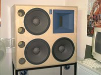
For Sale New Altec 604 8H-III Speakers & N604-8C Crossovers

Continuing to purge my inventory as I physically diminish.
Speakers and crossovers are new and have never been removed from the factory packaging.
Great Plains Acoustics, the recent successor to Great Plains Audio (successor to the Altec Lansing Corp.), has a this package on sale from $4,078 to $3,465. It is out of stock.
$3000 plus shipping.

M

Active 3/4 way HiFi

Hello all, I am new to this form and DIY audio in general although I have long had a passion for audio. I currently own a pair of revel M106 and my father owns some Salon 2s. I am interested in making the "Best" Horn loaded "party" speaker. I am a big fan of music festivals and want to recreate that chest thumping bass and levels where I need to put my musicians earplugs in but as high fidelity as possible. I have been taking some inspiration from the likes such as funktion-one, hennessey sound https://www.hennesseysounddesign.com/point-source/ , and KV2 VHD2 https://www.kv2audio.com/products/vhd-series/vhd20.html . This sound system will eventually be placed in a "great room" likely a flown array to get even front to back coverage. I am currently thinking of 4" 1.4" exit beryllium compression tweeter such as https://radianaudio.com/collections...s/951-4-diaphragm-1-4-exit-compression-driver and possibly paired with one of these horns https://www.parts-express.com/B-C-M...ctivity-Horn-70x55-4-Bolt-294-6184?quantity=1 . Hennessey makes mid bass and subwoofer boxes that do 75-300 and 25-100hz respectively that I would like to emulate or possibly just purchase.

My biggest question still is how to complete the midrange likely 275/300-1???hz I want to have as high fidelity as possible but it also needs to be comfortable at 120 and reach up into that 130+db peak levels.
maybe https://www.madisoundspeakerstore.c...nx-003-e0073-08-6-graphene-cone-woofer-8-ohm/
or Purifi Ushindi 6.5" PTT6.5M08-NAA-08

I plan to do this all on active dsp crossovers with 7 separate amplifiers to get the timing, crossovers, and frequency response perfect.

Any and all advise is welcome!

Preventing resonances, should I add foam or something?

Hi

Further to my previous thread, this sub design has been cut and partially glued. It's a Focal 8 inch flax cone 4 ohm driver, tuned to around 30Hz. I've added an extra panel to the front to double up thickness and recess the driver. It will sit behind a wine rack in my kitchen music system. WinIsd models it flat to 30Hz at 105dB/1m. I've bought a mini Dayton LF dsp to provide a steep high pass filter below tuning as the enclosure is twice the Focal recommended size at around 1.5 cubic feet including port space. If anyone has a cheaper or better value idea for a high pass DSP, I'll be interested in that too as I'll be able to return it easily via Amazon.

https://subbox.pro/en/b/Dma3w9kjt

I will put it all together tomorrow, and just wondered if anyone had any advice, or comments.

Specifically, regarding resonances, should I add some foam or material to soak up any higher frequencies, e.g. on the inside left panel? Or is that just a waste of time and space?
Also if someone can point me to a guide on how to crimp the speaker terminals on the inside that would be very helpful.

Thanks.
PS. Here is the thread re the room if you're interested. https://www.diyaudio.com/community/threads/new-kitchen-setup.415463/

Diesis Mini Bookshelf 1979 refurb

Hello Chaps, been a while since I was on here and even had to reregister as my email has changed.
I just recently pulled my old Diesis MinI bookshelf speakers from the loft. I bought them new in 1979. They were made by Brian O’Rourke and marketed as Diesis. Brian went on to create Ruark Speakers with his son Alan. They are only down the road from me too. These speakers were very solid and fitted with SEAS tweeter and Woofer/mid, and a SEAS supplied crossover. i bought them after a blind test in the shop and they mistakenly played some Spendors and I went Oh yes. They said oops mistake as they are well put of your price , but these Diesis have a similar sound signature and he was right, they cost a bit more than my limit… But they are very smooth but with no colouration.
Ive been through some Dutton 33’s and 332‘s and more recently Rega RS5s but the little Diesis kept calling, especially as they are small enough for the missus to accept in the lounge.
Anyway, back to the present day:
Hooked them up and realized one speaker was quieter than the other. So did the usual and ascertained its the speaker not amp or anything else. Took them apart and saw to my dismay that the 2 woofers are covered in oxidation so that needs doing. Then noticed that the crossover looked a bit cooked on the one that was quieter. So I set out to try to ascertain all the values. Not so easy , so I hooked out the other crossover only to find it has different make caps etc. A bit odd as I bought them new so no one has fiddled with them.
So, I’m struggling to see what size the Inductors are. I can read the Caps on one crossover ok so that good. Also the resistors on that board , not so easy on the other board. Both the air cooled Inductors look ok and I’m to understand they rarely have a problem.
So here is the information I can see. Hoping someone on here can work out what I need to buy …

Crossover 1 :Has a sticker which reads : D 093 P 8ohm, 2-way 3120176, fc: 2000Hz.
Inductor; 6F8 5%
Caps 1; CEO 2SP 50V 12mF (K) The m is actually the symbol for micro but can’t find it on my keyboard.
Caps 2; CEO 2SP 50V 8mF (K)
Resistors 1; RGB5 10 Ohms J Noble62
Resistors 2; 5W 7 Ohms J Micron86
Crossover 2:
Inductor; can’t read at all
Caps 1 ; 12mF 50V
Caps 2 ; Can’t read till I remove it.
Resistors 1; D(ohms symbol) C. 811 4R7 5% 5W
Resistors 2; can’t read at all.

I will upload a photo of the crossovers. I have more photos if anyone needs extra.

Appreciate any help to get these up and running as to be honest id forgotten how nice they sound, even with one speaker a bit quieter… ( I have Attacama Stands for them.)

I know these are not or even were not state of the art speakers but do you guys think standard Alcap Caps and equivalent Resistors and inductors will be ok or should I go a bit more upmarket? I will likely use Falcon Accoustics or Wilmslow Audio as im in the UK.

Thank you guys, appreciate any help at all.

Cheers
Phil
IMG_5242.jpeg
IMG_5239.jpeg
IMG_5237.jpeg
IMG_5244.jpeg

Help with a 6L6 PP design

I still consider myself a newbie. I have put together a couple of amps, mostly monkey see monkey do. (no offense intended to the primates) I have put it together from scrap, used parts, and junk box parts. A PP 6L6 amp using a floating paraphase phase splitter, a 6SN7. Schematic attached. I'm a bit surprised that it starts to clip at just about 18 watts rms. I'm testing at 1 kHz, and yes, the output transformer was recovered from a 1940 RCA Victor floor standing phonograph/radio. But a "high end" one that had a PP 6F6 fixed bias amp, that claimed 19 watt. Any suggestions as to what I might have gotten wrong would be appreciated.

Amp is working sorta OK, especially given the low quality OPT. I am attaching a second image, which is a screen capture of my scope. Reminds me of when Polaroid Corp sold instant cameras specifically for Tek scopes. (Now you know how old I am). There are 3 scope traces: Blue and yellow are the output tube plates, violet is the output into an 8 ohm resistor load. I have fixed the imbalance in the magnitude of the two tubes, but I have not figured out what might be causing the "step" in the output waveforms, seen near the peak of the sin wave. Anyone seen anything like this before? Thx.

Attachments

  • Corrected 6L6 PP amp.png
    Corrected 6L6 PP amp.png
    12.2 KB · Views: 287
  • IMG_7938.JPG
    IMG_7938.JPG
    526.1 KB · Views: 224

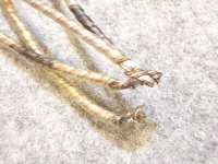
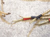
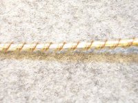
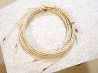
A new pair of peachy-keen tweeter hookup wires, being sold at a loss.

Up for grabs is a pair of Cardas Litz Wire twisted-pair 15-ga. internal hookup wires, 9 inches long each.

IMG_0942.JPG


Factory-terminated with silver solder. (Note, you can't just cut and strip Litz wire; you have to burn off the varnish that makes it Litz wire.)

There was a miscommunication re: quantity, and I ended up with an extra pair of twisted pairs. They cost me about $65 all told, but I can let them go for $25, with free shipping to US destinations.

PayPal payment, please.

john

Which type are Erie metallised cap for crossover Ditton 25

I have a question about a vintage speaker's crossover. I would like to recap the crossover of my Celestion Ditton 25. I would like to know if wise and with caps to choose from.

The crossover has 4 inductors and 4 groups of capacitors.

-First, a black Elap 50v 25uf, and

-three, with the same shap, red ''Erie'' metalised 150v 2uf A308, ''Erie'' ''metalised'' 150v 3.5uf A316 and ''Erie'' ''metalised'' 150v A316 3uf.

So there is one for each of the 4 drivers, the two turbine type tweeters have different one.

For the Elcap, it seems clear that is an electrolytic cap, but for the second it is less clear,

I gave a look online and the metallised cap is described as a fast cap. There seems not easy to find 150v electrolytic cap. So it is not an electrolytic cap, which is its type? Film?

The second mystery why there are two different model numbers.


A mate told me that the film cap could give a strident high. I listen to classical and early music so I won't experiment in this field.


In the past, I recapped my Leak 2060 with 3 blue electrolytic cap 50v brought from Falcon Acoustic in England. It was simple, I got ones with the same spec. It was a huge improvement.

For Sale Loudspeaker drivers and horns

After several decades of speaker building, I’m liquidating some of my inventory of speaker drivers, horns, and miscellaneous components. To wit:

(2) Faital 12FH520 12” neo woofers, used in excellent condition - $400

(2) Fane Sovereign Pro 8-225 woofers, NIB - $100

(2) Faital HF10AK compression drivers, used good condition - $300

(2) Dayton D250P-8 comp drivers, excellent - $100

(2) PRV D250Ph-S comp drivers, unused - $50

(2) Auto-Tech E-JMLC600 elliptical horns with 1” throat, used/excellent - $600

(2) Faital LTH142 1.4” horns unused - $150

As stated, all are in good-to-unused condition. All prices are for the pair, shipping not included, and everything is negotiable. I’d prefer CONUS only, but will consider international, and welcome local pickup. I’m in Tewksbury, just north of Boston. Payment accepted: Paypal F&F, Venmo, Zelle, Postal Money Order and cash.
  • Like
Reactions: swak

Teflon Coupling Capacitors 0.1 0.2uF for tube Amps

Hi, I am looking to start a new thread, on 0.1 uf and 0.22 uf Teflon Coupling Capacitors and any other 0.1-0.2uf suggestions for tube amplifiers under $60 USD each

The Russian FT1 FT3 K72 and now Solen SQ3 series all fit this category.
I am sure their are others and wonder what results people have had with these .
Their are Blogs comparing the FT1 FT3 and K72 to Vcaps but wonder how others have found them in coupling positions between say a driver tube and out put tube ie 6SN7 > 2A3 /300 single ended , or E280F > 2A3 /300B , Ra, CCS or Choke loaded

Max performance lag compensated amp

I've been enjoying the modified Parasound HCA-800 mkII. It's a simple lag-compensated amplifier, with a lead-lag network at the IPS to add some 2nd order loopgain roll off. No fancy modern TPC or TMC, just a classic topology that dates back to the JBL SA-600. It sounds live, with solid bass, it's a super detailed yet easy listener.

So what's the best we can do with lag compensation?

Here's an evolution of it with generous stability margins, and distortion products around -125dB, and that's with TO-3 outputs! Haven't built it yet but this might be the next project to be put to board.

Attachments

  • lag_stab.png
    lag_stab.png
    32.7 KB · Views: 365
  • lag_imd.png
    lag_imd.png
    23.5 KB · Views: 365
  • lag_schem.png
    lag_schem.png
    47.2 KB · Views: 373

Purpose of Focus Offset trimpot on CDM-1

Just out of curiosity: what is the purpose of the variable resistor 3132 (FOCUS OFFSET, 47k) on the Philips C.D.M-1 mechanism? Neither the service manual of the mechanism, nor the service manual of the CD player (Marantz CD-94 in my case) does mention anything about this adjustment.
The only focus related adjustment is just setting the height of the turntable with a Torxx screw until the voltage on the focus motor is 0V +/-100mV.
This variable resistor apparently balances the input offset of the Focus Error amplifier uA741. Would it make sense to disconnect the flex cable from the photodiodes going to the NE5514 preamplifier, adjust 0V on the output of the uA741, reconnect the photodiodes, and then do the turntable height adjustment? In other words, do electrical offset zeroing first (open loop) and then do the mechanical zeroing (closed loop).
  • Like
Reactions: weissi

How small box can an Faital Pro 18XL1600 work good in?

Have 4 big Faithal 18XL1600 that I buy 5 years ago that i never uses,
They was/are mounted in 4 big PA-boxes, but im thinking if I can build some "nicer" cabinettes for them and also a "potent" MTM or a MM/TM.

Maby use two 18XL1600 per side?
They are 8 ohm drivers!

My biggest "worry" is that I think they will need BIG boxes to "work good".
So I ask you guy´s, how many liters does it need "as a minimum", to play desent?

regards John

Attachments

Second opinions needed on a system design

I have restaurant and we need to replace our sound system with a new one that can produce clear sound with ample headroom in case we need to play things loud (which we do occasionally). Over the last two weeks, I worked with our DJ and one of our in-house technicians to design a replacement system and I'd like to get much needed second opinions from you guys on what you think of our plan. Harsh criticism is welcome whenever warranted. Below are the details and in the bottom you should see the layout of our venue.
  1. Budget: $20,000 with all the equipment will be purchased from the US. We still need to pay for shipping, customs, and installation which'll be another $20k.
  2. Venue Design:We have three areas. A restaurant, a sushi bar, and a lounge. The restaurant is the biggest in size and music start to get loud at 11p until we close at 3a. The sushi bar has a couple big tables and a bar seating area where we keep the music volume on the low end just as background. The lounge seats around 30 people and we play background music a little louder than the sushi bar area but not close to the restaurant area.
    1. The restaurant: We have a seating capacity of 150 guests plus the floor staff (around 40 on average). The area is oddly shaped with the following dimensions: Length: 21.5m in the shorter lower edge and 23.1m in the upper longer edge. Width: 14.8m, and ceiling height: 6m. There are two beams in the middle area which we can use to mount speakers. Other than that, we only have the upper wall and the walls on the right and bottom sides of the restaurant. The wall on the left side is a floor-to-ceiling glass wall except for the three beams shown in dark grey in the layout. The DJ booth is almost centered horizontally (shown in the upper side of the restaurant area in the layout).
    2. The sushi bar: The dimensions of this area are: Length: 10m, width: 8.4m, and the ceiling height is 6m. It is open to the entrance area and the entrance area is visually blocked from the sushi bar area by some artificial greeneries.
    3. The lounge: The dimensions of this area are: Length: 14.5m, width: 7.7m and the ceiling is 3.75m. It's open to the sushi bar area and visually blocked from the sushi bar area by decorative greeneries as well. So there is no hard barriers of any kind.
  3. The plan: Our thinking was that we have to incorporate pendant speakers that have a wide enough dispersion angle as the backbone of our system, supplemented by wall-mounted speakers to provide a fuller sound coverage without being overpowering. So here it goes:
    1. The restaurant: In the restaurant area, our plan is as follows:
      1. eight JBL Control 68HP pendant speakers (passive) in a two-row configuration with 4 speakers mounted along each of the two longer sides with the two on the edges of each row being 2.5m away from the two side walls, and the remaining two are placed 5.5m away from each other in this rough placement for one row example: 2.5m X 5.5m X 5.5m X 5.5m X 2.5m (the X represents the speaker). The two rows will be about 5m from each other. We plan to place them 1.5m from the ceiling (4.5m from the floor).
      2. two JBL Professional Control 28-1L speakers (active) mounted on the wall behind the DJ booth to its left and right sides angled downward. These two are meant to provide enough sound to the area in front of the DJ booth which is usually preferred by customers who love loud music.
      3. ten JBL SLP14/T wall mounted speakers distributed across the restaurant area to provide just enough sound for a fuller experience without being overly powerful. The basic thinking behind it is a budget-friendly option that can eliminate dead spots without being too powerful.
      4. two JBL Professional PRX918XLF subwoofers (active) which will be placed on the floor in front of the DJ booth slightly angled toward the sides of the restaurant.
    2. The sushi bar: In this area, our plan is as follows:
      1. one JBL Control 68HP mounted in the ceiling at 4.5m from the floor between the two tables (the tables placement in the layout is not accurate. They are closer to each other). It should provide enough background music to the two tables and the bar seating area.
      2. two JBL SLP14/T wall mounted speakers on the wall of the bar facing the bar seating area and two tables.
    3. The lounge: In this area, our plan is as follows:
      1. six JBL Control 68HP pendant speakers placed in a two-row configuration with the first one being 2.5m away from the two side walls (left & right) and 3.9m away from each other. The two rows will be about 2.9m away from each other. They'll be 3.75m from the floor (the actual floor height is 6m but there's a secondary decorative steel ceiling at 3.75m from the floor which has many openings where we can drop the speakers through these openings).
      2. two JBL Control 60PS/T subwoofers (passive) which will be centered vertically and horizontally will be evenly placed across the seating area.
    4. Amplifiers: As per our calculation, we need 5,350w of power to power our 27 passive speakers and 2 passive subs. We looked at Crown (XLi, XLs, CDi), QSC GX7, and Behringer NX4-6000. We ran different budget and performance simulation scenarios. I immediately excluded the Behringer fearing its reliability (or lack thereof). The Crown XLs was slightly out of budget but can be manageable. The Crown CDi was way out of budget. The QSC was similar to the XLs in terms of budget. However, what we couldn't figure out is what we'd be gaining and losing in terms of performance under each scenario. Here is what we came up with which'll provide us with 5,800w of power:
      1. two Crown XLi3500 Amplifiers
      2. two Crown XLi2500 Amplifiers
      3. one Crown XLi800 Amplifier
    5. Processors and other equipment: Currently, we have one dbx Venue 360 processor. In our calculation, we will need another dbx Venue 360 and an ART S8 Signal Splitter to be able to process the sound as per our needs. The farthest speaker from the rack is ~37m. We will use 12 AWG cables throughout. Please check the layout for the location of the equipment rack (red rectangle to right).
This configuration will cost us $16,000 (without shipping, customs, and installation), so it's within our budget.

What have we missed? What other alternatives should we consider?

Source Options for TV & Music into Hypex Amps

Hi all,

Really wasn't sure what to call the topic or the correct place to put it so hopefully this is ok.

I'm looking to setup a room for mainly listening to music, but tv will occasionally be played also.
My current gear will be a new set of speakers i have just finished, 3 way active with Hypex amps.

My main questions relates to how I ideally get my audio sources to the speakers.
Eg. I was originally going to put these speakers in a different room and use the preouts of my Denon X3800h, but i've changed that plan and
only have an older AVR in this room with no preouts.

Ideally I'd like a digital source to feed the hypex amps for music. I don't mind how i get the tv audio to the speakers.
The main thing i want is a volume control so i dont have to modify volume on the hypex amps.

I really havent had much to do with amps/media streamers etc, aside from AVRs, so if you can point me in the right direction here it would be much appreciated.

Hopefully this isn't too vague. Thanks in advance!

Break In

The role of dominant poles and component quality in high-power electronics and audio systems is crucial. Defective or substandard semiconductors can act as unintended oscillators, generating structural noise and high sound pressure levels (SPL) with minimal energy input. This chapter explores the historical context, the evolution of semiconductor technology, the concept of break-in, and strategies to manage dominant poles and improve component quality.

In the early days, solid-state amplifiers and Class D amplifiers faced significant challenges due to low-grade semiconductors. These components often exhibited high noise levels, distortion, and reliability issues, which affected the overall performance of audio systems. Vacuum tube technology, with its linear amplification characteristics and higher tolerance to imperfections, initially maintained a competitive edge.

Early semiconductors had inconsistent material quality and manufacturing defects, leading to unpredictable performance and higher noise levels. Circuit designs did not fully leverage the potential of solid-state devices, resulting in suboptimal performance. The limitations of early semiconductors exacerbated switching noise and "Class D glare" in amplifiers. Ineffective filtering techniques further increased these issues, making it challenging to achieve clean audio output.

Advancements in semiconductor manufacturing and design have addressed many of these early challenges. Today, high-quality semiconductors are characterized by superior material properties, precise manufacturing, and optimized performance. Modern semiconductors are produced with high material consistency and manufacturing precision, reducing noise and enhancing performance. Circuit designs now fully exploit the strengths of semiconductors, incorporating advanced feedback control, better thermal management, and optimized signal paths.

High-quality low-pass filters and other advanced filtering techniques effectively suppress high-frequency switching noise in Class D amplifiers and digital power supplies. The use of inductors and capacitors with appropriate values and high-quality materials ensures effective noise reduction. Digital signal processing (DSP) techniques manage noise and improve signal integrity in digital power supplies and Class D amplifiers. Real-time correction and enhancements through DSP help mitigate imperfections and enhance audio quality.

Break-in refers to the period during which electronic components stabilize after initial use, affecting their performance. Both semiconductors and capacitors benefit from a break-in period, which can lead to improved performance over time. Semiconductors may exhibit changes in their electrical characteristics during initial use, leading to performance improvements as they stabilize. Long-term changes due to heat and electrical stress can further enhance performance. Electrolytic capacitors benefit from a break-in period during which the dielectric material stabilizes, improving performance. Film and ceramic capacitors can also experience improvements with brief electrical conditioning.

Dominant poles are frequencies where minimal energy input can significantly excite a device, leading to potential performance issues. These poles are critical in both semiconductor and speaker systems. The resonance frequency (Fs) of a speaker is a dominant pole where the speaker cone naturally vibrates with minimal energy input, potentially causing unwanted resonances and distortions. Management strategies include using damping materials, notch filters, and structural reinforcement to mitigate the effects of Fs. For semiconductors, the transition frequency (ft) is a dominant pole where the gain starts to decrease significantly, potentially causing instability and oscillations. Operating below the dominant pole, using high ft design, and effective filtering can help manage the effects of ft.

Defective or substandard semiconductors can act like unintended oscillators, generating structural noise and high SPL with minimal energy input. This is due to the crystal-like structural oscillation inherent in low-quality semiconductors. Defective semiconductors can resonate at their dominant pole with very little energy input, similar to how a crystal oscillator works. This efficient energy conversion leads to significant excitation with minimal power. When excited at their dominant pole, these semiconductors can produce high SPL, creating structural noise that is perceptible and often uncomfortable to the human ear.

High-end manufacturers implement stringent quality control measures to ensure component reliability and performance. Grading components based on performance metrics and structural noise is crucial for maintaining product quality. Components are subjected to current passing tests to measure structural noise and performance, and are then graded from Grade 1 (highest performance) to Grade N. Only Grade 1 components are used in premium products to ensure the best performance. For high-end products, replacement parts should be sourced directly from the manufacturer or the product should be returned for factory servicing. DIY repairs or local servicing with ungraded components can degrade performance and lead to dissatisfaction. Directly contacting semiconductor and capacitor manufacturers to request high-grade components ensures stringent quality standards. Purchasing components in bulk from reputable suppliers like DigiKey or Mouser and grading them yourself is an option for ensuring quality, though it requires specialized equipment and expertise.

Dominant poles and component quality are critical factors influencing the performance and reliability of high-power electronics and audio systems. Early challenges with low-grade semiconductors underscored the need for high-quality materials, precise manufacturing, and advanced design techniques. Modern advancements, combined with rigorous quality control and grading, enable the creation of high-performance, reliable electronic products. Understanding and managing dominant poles, structural noise, and the break-in process are essential for professionals striving to achieve optimal performance in their designs.

This chapter provides a comprehensive overview of the critical factors influencing the performance and reliability of high-power semiconductor applications. By incorporating proven facts and modern practices, it serves as a valuable resource for professionals in the electronics industry.

Acoustic 450 Repair

Hi, I'm trying to repair an old Acoustic 450 amplifier.
I got it after someone plugged the amplifier to 230V mains with the power transformer was set to 115V and someone in the past bypassed the 7A fuse so many components went faulty. The bridge rectifier and the main filter caps was faulty as well as the original drivers and two original output caps. I replaced all the output transistors with 2N3773G and the drivers with 2N5320 and 2N5322 as well as all the electrolytic caps and diodes on the power amp circuit.
With a variac supplying a low operating voltage and a bulb limiter with the output transistors and a 8 Ohms speaker load connected both drivers are getting extremely hot and after 20 seconds or so both getting burnt.
I've already tested all the small transistors out of circuit with a Chinese LCR TC1 and all tested well.
As far as the PSU, the bridge rectifier and the main filter caps were faulty and were replaced with new ones.
With new drivers and with a 100ACV from the variac (power transformer wired for 230V) and without the power transistors the DC voltage at the speaker output is varying from 7.5V on startup to 5V after 1 minute.
How can I make this amplifier to work without blowing the driver transistors?

Attachments

eBay mono LM1875 kit

(Mod note... thread split from here:
Beginner's Gainclone, HiFi LM1875, The Amplifier Board)

-----------------------------------------------------------------------------------------------

Hmmm Been looking at this as well.
Couple of points;
I located the 'Original'.. and quite good actually..design (haodiy.net) of the currently widely available on ebay, as the 'cloned' 2$ lm1875 'kit'.
PCB layouts..Amp and PS are downloadable at haodiy.net..for DIY PCBs.

Ebay Vultures have shrunken the pcb tho (cheaper to make).. but it's still a good usable layout .. absolutely so for the price 😉
Their Odd low quality parts / value substitutions are definitely for the trash bin though. Just use the pcb.

Daniels' final circuit, seems as oddly complex.. IMO .. with 24 parts.
Certainly seems so as compared to the often described as 'excellent' ESP layout which uses Far fewer parts (15).
Note though that Both the Hao design author And Rod Elliot (esp)both state that the 1875 approaches High end audioweenie sound.. but does not quite achieve it.. all claims aside

Your choice... Suggest trying either the Haodiy OR the ESP circuit as experiment, then comparte Could be interesting and worth reporting back on it?

Tuning / Tweaking of BP 115 A

Hello,

I bought some nice two way Bluetooth loudspeaker with accumulator (battery).
Its a Thomann cheapo named Fun Generation BP115A with 15 inch bass and big tweeter. It has 93db efficiency (I found the repair driver PDF spec), stiff paper bass diaphragm and I guess - as far as I could see - a tweeter with a decent sounding mylar diaphragm. Only the tweeter seems to have a 12 db filter with 4 Ohm resistor. Bass seems to be directly driven by the amp.

In original condition it sounds as most PA loudspeakers o.k.. But in my ears - like in most PA systems - some typical hifi faults are built in. In order to bring efficiency up with a trade off in sound quality.

It is easy to open the plastic loudspeaker enclosure. The box is pretty undamped (only just a little little bit black BAF wadding and a highly tuned bass reflex. I want to turn this speaker in a good sounding hifi speaker capable of deeper bass than the 60 Hertz lower cut off frequency.

So tuning - tweaking of the FunGeneration BP 115 A loudspeaker was done:

1. putting some damping on all surfaces and fixing it
2. a method I prefer to get good sound is covering the bass diaphragm on the front side with aluminium foil.
3. Tuning the bass reflex to 30 Hertz as I want to hear the lowest octave - even if it is surely sloping.


You can see some fotos of the loudspeaker which are self explaining.
The aluminium foil is just simple foil used in the household. Glue is simple glue which fits for paper and metals.
You cut the foil into pieces (form of cake pieces) put thinly the glue on the backside of the foil an then fix it with the use of your fingers to the diaphragm beginning from the outer edge. I am used to do this since the year 2000. I had for ten years a website online exactly describing how this is done with thinner foil from the gold smith but it seems to be too much work for the most Do it yourselfers to try this tweak out. As I (nearly) never found anyone reproducing this method.

From theory it is known that the combination of metals and paper can bring a lot more stiffness to the diaphragm (known since the 60ies, but history of loudspeaker building describes this in patents since the 30ies of the last century - it means right from the beginning of loudspeaker production of the dynamic type). For germany it was Dr. Emil Podzus (aluminium foil and hard foam), later it was english speaking D.A. Barlow in the 60ies with duraluminium sheets and expanded polystyrene of thick quality. In germany these aluminium foiled loudspeakers are known as Podzus-Görlich loudspeaker drivers. Mr. Görlich was helping out as a young man at the factory of Mr. Podzus. He later produced these diaphragms with aluminium foil and hard foam. He does it until today.

I measured the loudspeaker diaphragms paper + aluminium very often. One sided and both sided (last means it is a sandwich-cone). Coating of the driver on just one side brings resonances down - makes the speaker sometimes more linear - but always the loudspeaker driver becomes much more stiff and has therefore a significant better impulse reproduction.

Best is this checked by ear while covering one driver with aluminium foil and leaving the second stereo speaker undoped. You can then use your balance knob on your amplifier for an A / B listening test.


Here about the theory:

D.A. Barlow: The Development of a Sandwich-Construction Loudspeaker System. Page 159-171. From the AES anthology of articles on loudspeakers, article written 1970.

Citation begin (page 160):
"As paper cones are thin, these resonances are bending modes. The stiffness of a material in bending, for any given geometry and edge condition, is proportional to Young`s modulus and the cube of the thickness, ignoring variations in Poisson`s ratio. ... On this basis, paper is much stiffer than metals (except beryllium) in spite of its much lower modulus, and lower density materials such as expanded plastics are even stiffer, as may be seen in Table. A method of obtaining still greater stiffness is sandwich construction. ... In bending, the maximum stress and strain occur at the outer fibers, the material at the neutral axis being unstressed. Better use of material can thus be made by concentrating it at the outer fibers. A familiar example is the tube. In the case of large areas, the same effect is obtained by using a thin high-modulus material for the outer surfaces, and a light-weight material or form of construction for the core. ... This sandwich will of course be much stiffer than the same total weight of either material used separately. The skin material should have the maximum ratio of modulus/density. Beryllium, the best material, is impractical due to difficulty of rolling and possible toxicity, so aluminium is the obvious choice. The core should be as stiff as possible in the thickness direction and have minimum density. Honeycomb aluminium or impregnated paper are frequently used in aircraft construction and could be used for flat diaphragms."
Citation end.


The Thomann bp115 a becomes after this tuning much more listenable and precise. I use it with the loudspeaker put on the side as the tweeter and the bass seem to be better time aligned than with the tweeter upside. (Listening position loudspeaker on the floor and listener standig upright).

The mylar tweeter sounds quite good, I like it.

Dragan from Germany

Attachments

  • IMG_20210806_115859.jpg
    IMG_20210806_115859.jpg
    388.2 KB · Views: 584
  • IMG_20210806_172715.jpg
    IMG_20210806_172715.jpg
    589.3 KB · Views: 574
  • IMG_20210806_120233.jpg
    IMG_20210806_120233.jpg
    420.8 KB · Views: 570
  • IMG_20210806_120244.jpg
    IMG_20210806_120244.jpg
    506.2 KB · Views: 550
  • IMG_20210806_120321.jpg
    IMG_20210806_120321.jpg
    360.4 KB · Views: 561
  • IMG_20210806_120525.jpg
    IMG_20210806_120525.jpg
    516.2 KB · Views: 438
  • IMG_20210806_121805.jpg
    IMG_20210806_121805.jpg
    457.2 KB · Views: 411
  • IMG_20210806_123022.jpg
    IMG_20210806_123022.jpg
    562 KB · Views: 399
  • IMG_20210806_132448.jpg
    IMG_20210806_132448.jpg
    412.8 KB · Views: 427
  • IMG_20210806_133042.jpg
    IMG_20210806_133042.jpg
    664.9 KB · Views: 442

Redo?

I've had a 70s Pioneer PL 560 for several years, and after making crackling noises at start up and finish for the past 4 years or more, the left channel needs a recap I think, as it's quit completely.
My favourite turntable is an Acoustic Research AR XA, and if I need a shop to do a recap anyways, I'm wondering if anyone has made this into a stripped down fully manual turntable.

My AR XA is comparatively shocking underneath- electronic parts wise, apart from the motor, it looks like it has a run motor cap, and a thump suppressor cap at the motor switch. That's it.
The AR has gotten me used to a fully manual turntable.
I love the Pioneer tonearm compatability with so many of my cartridges, easy availability and affordability of extra headshells, and stylus profiles I've already collected.
Has anyone modified one to have the simplicity of an AR XA? One thing I'm considering is rca socket output, to facilitate using leads I already have of several differing capacitances.

High SPL 3 Way

This is what I have came up with so far:

Schiit Bifrost DAC > MiniDsp DDRC-88A > DIY Hypex Ncore based amplification > active 2/3 way.

I want to use the Beyma CD10ND or their neo 1.4” for my HF, paired with an SEOS 12/15 I've done countless hours of research on them, and they appear to be exactly what I'm after. At 111db/w and 70w RMS they should be able to hit 129db. Their minimum crossover is 1,200hz, but I’d like to cross them around 2,000hz if I use a mid.

I haven’t modeled anything, or done a lot of research on my mid at this point. I know that I will definitely have to horn load it to get close to the output of the CD and woofer without multiple mids. I’d like to avoid multiple mids to avoid comb filtering if possible. Horns seem extremely hard to find for a 6-8” midrange. I’m open to all suggestions for a mid/horn combo that’ll reach into the 125+ spl area with pretty low distortion.

For my woofer, I'd like to go with the Beyma 15P80ND, or Faital Pro 15FX600. I've dome some modeling on both, and while I'm no wizard on WinISD yet, they appear to model very nicely. With the efficiency and power handling of both options, it should be able to match output nicely with the CD. I'll be measuring with a Umik and adjusting levels accordingly once built.


The LF will be handled with several high efficiency 18's or 21's on Inuke power (preferably two 28hz tuned Devs loaded with San21's on an NX6,000), and 2-4 cheaper pro 18's on a NX3,000/6,000 to even out the nulls but I'm still working on that aspect as well. Whatever combination I go with will be crossed anywhere from 120hz-80hz to them.

With the 4 presets, I'll make one outdoor event setup, use 2 others for the 2 main venues and leave one open for special shows. The largest venue they will play in is 5,000sq/ft and the largest outdoor gathering they'll provide sound for is 250 or so people.


Let me know what you all think! Again, I’m open to any and all suggestions. This is just what I have came up with so far. Thanks for any input, or experiences. I appreciate it all!
  • Like
Reactions: DblAA

Unbalanced source > balanced load and vice-verse

In 2010 or 11 Bruno Putzeys posted how proud he was of the quality of the differential input on his NC400 amp. Bruno sternly cautioned builders to never install an RCA input for unbalanced sources, instead preferring:
Unbalanced source RCA output > RCA to XLR adapter at the source > balanced IC > NC400 XLR input. He said such application approached the performance of a balanced source.

I "tried it both ways" as Deputy Barney Fife would say and IMO Bruno gave good advice (shocked, not.)

If using a simple XLR to RCA adapter, is this the best method to connect a balanced source > unbalanced load?

Balanced source XLR output > balanced XLR IC > XLR to RCA adapter at the load > unbalanced load. Does this approach the performance of a balanced load?

Dayton-Wright ESL

I just acquired a pair of DW ES speakers w/o any ID on them as to model. I am a total rookie when it comes to the ES world. They have 10 panels and 2 tweeters. The bias supply is an ST-300A. I’m reasonably sure there is no gas left in the bag. The person I got these from tried to power them up. One side crackled and the other was dead. The story I got was they were in a damp basement for decades. I took the grills off due to mold and wiped down cabinets. It looks like one speaker has a corroded connector in need of replacement. Any info on these dudes would be helpful. Did some on-line info gathering but haven’t found any links to manual or model #
Dan

Preamp recommendations

Hi guys..at present I am using a DEQX HDP Express ii preamp/DSP controller/crossover/etc to feed XLR output from an Ian Canada DAC stack to DIY KT120 tube monoblocks which drive DIY open baffle mains. The DEQX unit also has 2 subwoofer outputs, both connected to active subs with line-level and LFE inputs only.
I would like to build a preamp to replace the DEQX unit - I would lose the DSP speaker and room correction capabilities of the DEQX, but I have a MiniDSP 2x4HD which I could use for subwoofer crossover/alignment, and JRiver convolution for room and speaker refinement (most of my listening is computer-based digital files).
I would want a remote-controlled preamp, possibly with tone controls (bypassable), with at least 1 balanced input, 3 RCA inputs, budget up to $1000 (US). I have had a reasonable amount of DIY experience, building 3 lots of speakers, 2 tube monoblocks and a tube phono preamp.
Any recommendations gratefully received 😉

For Sale Amp Camp Amp Redux - Complete kits

Edit 2024/04/18: New kits are now available on my website: reduxkits.com


I designed an easy to build, reduced cost version of the ACA to encourage more people to get into building amplifiers. In October of last year, I put together a batch of kits and we built 30 of them at Burning Amp 2022. I'm offering the remainder of the kits for sale here.

Each kit has all the parts required to build two monoblock amplifiers. Switching power supplies from Jameco are included.
All passive components were sourced from reputable US suppliers. The active devices came out of Nelson Pass' not-so-secret stash .

Read more about the design in the main discussion thread: ACA Redux
Check out the build guide written by 6L6: ACA Redux Build Guide

Happy building!

ACA Redux Front 1600x1200.JPG


Bottom - standoff.jpg


PCB Front.jpg


Parts bags.jpg


Power Supplies.jpg

JBL - like waveguide for line arrays?

I hope you all don't mind if I post something that's purely theoretical. I'm afraid I love line arrays but may never actually get to build one. I've been thinking about the subject of line sources for a while and recently stumbled upon a new (to me) waveguide from JBL that has me thinking about them all over again.

The ideal line source is a single long and skinny array which also goes down to at least 200 Hz or lower. The problem we are faced with is often getting enough bass vs. getting acceptable horizontal dispersion. Long ago I ran into flat ESL speakers which were about 8" wide which sounded great in exactly 1 location in the room. I then often wondered if there was any way of putting a "spoiler" of sorts in front of them to widen the dispersion. Same kind of issue applies to line arrays made from 4" circular drivers. They get deep enough but eventually beam around 4-5 kHz.

Then I saw these JBL speakers with a waveguide that improved the off-axis performance of an otherwise too wide a woofer and I wondered: Is it possible to build a line source out of 4" drivers with a similar idea? If so, is it something that would even apply to a flat ESL design?

1722186575770.jpeg

For Sale [ADL] PEERLESS by Tymphany 830669 12"paper cone SLS subwoofer x 2

I have 2 of the above Tympany 12" subwoofers for sale. BNIB. Surplus to requirements after a project change.
Only 1 of the drivers has been out of the packaging to check fitment on the speaker baffle - clean and as new.

A$100/ea. Would prefer local pickup. Can post (Australia only) at buyers cost if required.

Attachments

  • IMG20240731103655[1].jpg
    IMG20240731103655[1].jpg
    407.2 KB · Views: 69
  • IMG20240731103738[1].jpg
    IMG20240731103738[1].jpg
    383.8 KB · Views: 70
  • IMG20240731103818[1].jpg
    IMG20240731103818[1].jpg
    290.2 KB · Views: 68

Hello from France

Hello, I’m from Versailles, France and I’m interested in analog electronics, not necessarily linked to audio (sorry 😉

I’m from the generation that saw the apparition of fantastic components like the LT1028, from a time when HP was really something, from a time when everything that Bob Pease or Jim Williams would write was a gem that needed to be studied extensively. I still vividly remember the day my company gave me a 2465B, the Rolls-Royce of oscilloscopes of the time... But like so many, priority changed, and I switched my job to digital electronics and then software.

35 years later, maybe it’s time to go back to my first love, as an amateur.

Stetsom 21000EG RCA grounding issue?

i recently repaired this amp with new fets and a few broken grounding traces to fets and everything seem to check out after. i did one last startup before stress testing it a bit and i saw the amps spiked and big sound from my test speaker, after a bit of testing i found out that after removing the probe something causes it to wack out, spiking current and a ton of voltage on speaker and protect light swithes fast along with a buzzing noise. theres no dc across the speaker terminals and so on so iam thinking that the GND for rca might be wrong and grounding throught the ocilloscope. im running a pico scope and rca directly from pc for test sound and a RND 340-kwr-103 as power supply and have never had this behavior before.
ive checked the gnd trace from input jack but cant figure out where it ends.

any input anyone?

Fender 5F1

How y'all doing?

I've got a Fender Champ 5F1 guitar amp that has a crispy 22k ohm resistor on the speaker jack.

The amp now buzzes a lot, varies with the loudness pot. Funny thing is that it buzzes loudest from mid to high volume, decreases when the pot is turned to the loudest setting. That's usually too loud.

Does this sound like it could be a bad resistor? I'm going to go ahead and change the resistor, just wanted to get some ideas in case this isn't the problem. The crispy resistor is the only thing that visually looks bad. I tried different tubes.

Thanks!

Attachments

  • champ_5f1_layout.gif
    champ_5f1_layout.gif
    38.2 KB · Views: 578

6L6 PP Amp - Strange distortion - something like crossover?

Pardon me if this is the wrong place to post. Still getting used to forum. A few days ago I posted about a 6L6 and the expected power for a PP design that I cobbled together. I came back and added a 'scope trace that shows some sort of small step voltage change near the peaks of the waveform. Perhaps the edit/addition went unnoticed? The edit is at the top of the thread, to my original post. The original thread is here:

https://www.diyaudio.com/community/threads/help-with-a-6l6-pp-design.415228/#post-7739172

It includes the circuit schematic, scope trace and explanation. Thx

Rogue Model 100 Power Amp transformers

Hello folks, I believe this may be my first post here. I had an older Rogue Audio 100 power amp with a broken circuit board. I managed to salvage some parts such as the transformers. I really don't know much about them such as their rating but they're in very good shape. I don't want to just throw them in the trash so am looking for someone who may want/need these for a project. I'm not looking to get rich. I honestly don't know how much to ask for them but I'm open to all offers. I assume they won't be cheap to ship. I have one ( the biggest one) in a flat rate box now. I believe the shipping will cost $18.40 for that one. It may be more for the two smaller transformers. I'd appreciate any help. Thanks

Luxman M-383 Circuits

Hi Everybody -
As clearly there is nowhere a Service Manual for the Luxman M-383 available, I decided to make one myself.
I have analysed an existing M383 in detail and made up 7 pages of circuits, with all the component numbers and types.
I have added several measured voltages.
I will send a PDF to any person interested, for a modest contribution.
(I am not a company selling manuals, just a Luxman Fan!)
paul

what is the best speaker cable to bring low THD to the voice-coil

what is the best speaker cable to bring low THD to the voice-coil?

By building a low THD Amplifier and having low THD speakers this question came to my mind.

I do not want to start some voodoo threat - I want to know what makes sense from the technical site.

There is a lot of high frequency around us and i thought a shielding might be a good thing to prevent the high frequency creeping into the amplifier and disturbing the feedback loop with the result of a bad sound. So i bought some shielded 2x0,75mm² cable, connected the 2x0,75mm² as usual and the shielding to the amplifiers ground (a: directly; b:via resistor). It showed up, that in both cases the sound gets worser than before. A look at the oscilloscopes screen showed the reason: the shielding worked as an antenna and did the opposite of what it was intended to do.

Looking around in several forum showed only subjectivists views, none of them showed any technical description...therefore some questions:
- is shielding necessary / useful? If yes - how should it be done? If no - why not?
- is a ferrit clipped on the cable helpful? (as it is dampening common mode signals that reached the cable)
- does shielding help, even when it is nowhere connected? (as it is good practice in KNX home automation cabling)
- what is the optimal diameter for the cable? (with respect to the skin-effect)
- is a twisted pair better than a parallel cable? (as signals that reach the cable are inducted in opposite direction and therefore cancel)
- is the star quad configuration better than twisted pair? (as it promises a better immunity to magnetic fields)
- is coaxial-cable the solution? ( as it is shielded and, referring to cable-theory, all the inductive and capacitive fields from the current that is running through the cable happen inside, and the shielding works as such when connected to ground)
- what is the best way to test and find out?

At what voltage and frequency defining the OPTs leakage inductance

At what voltage and frequency defining the OPT's leakage inductance ?

Measuring Leakage Inductance Lsp is usually defined as shorting the secondary and measuring the inductance on the primary winding.
However, Lsp is strongly dependent on applied voltage and frequency as shown in the attachement.
When a transformers primary inductance Lp is specified at 230V@50Hz, it will simply not be possible to use this same voltage and frequency with a shorted secondary winding because it will blow the OPT into pieces.
Nevertheless, to calculate the quality factor, one has to know the corresponding Lsp because Qf = Lp/Lsp.

In the attachment below, several Lsp measurements are shown measured with a VNA with three different voltages, resp 1Vpp, 2Vpp and 4Vpp, resulting at 50Hz in resp 31.9mH, 22,5mH and 15.2mH.
So, Lsp is inversely proportional to the applied voltage, almost with the square root.
Going upwards in frequency all curves are coming together independent of applied voltage, resp 1.55mH@500Hz, 1.15mH@5Khz and 1.15mH@50Khz.
Interpolating this from 4Vpp to 230Vrms would result in 1.19mH at 230V, but how far off can this be ?

Hans

Attachments

  • Lsp.jpg
    Lsp.jpg
    232.7 KB · Views: 78

Give-Away (or Raffle or Sweepstakes): Vera-Fi Audio Vanguard Scout Loudspeakers (MSRP $299 the Pair)

Jack Baruth is best known as an automotive journalist. But he is a music lover and musician and audiophile and guitar collector. Jack's blog is called Avoidable Contact Forever. There is content that is behind a paywall, but there is a lot of Free content as well.

One item that is not behind a paywall is the above-referenced random giveaway of a pair of Vera-Fi Audio Vanguard Scout Loudspeakers. You enter by sending an email. The entry period closes Tuesday, August 6.

Win These Vera-Fi Speakers

Best of luck!

john
  • Like
Reactions: Roppu and adason

Help with Alembic F-1X/Clarostat Pot

I'm cleaning up a friend's preamp and need to replace a pot. It's a Clarostat, the back is stamped:
Alembic
475-001
20 9818
Mexico

I'm replacing because it tested linear from 0-380kOhms (1-8 on dial) then dropped sharply toward 0 (from 8-10). Based on that line's trajectory, I'm guessing it's a 500k pot, but if anyone could confirm that would really set me at ease for replacing. Also, by any chance does anyone have a wiring diagram so I don't have to decode resistor bands to test everything? Thanks so much!

Suggestions for 95 dB tweeter?

Hi guys
Im making a speaker for some outdoor concerts, and Im struggling a bit. I need a tweeter. I find it hard to find something in the realm of 95 dB sensitivity, and was wondering if you had any suggestions. It would be fine, if it was some waveguide or something that did the trick. As long as I land on something, where I don’t have to lower the sensitivity on my woofer. (As it is an outdoor build on batteries. I want it to play as loud as possible)


Thanks!

The frequency response of the FaitalPro 10” that I have laying around looks like this.
IMG_5793.png

Cizek Model 1

I picked up a pair of Cizek Model 1s this weekend for $5 (on a whim and knowing nothing about them but they looked cool). The cabinets need some refinishing but are solid, the grilles and foam on the front baffle is shot, the tweeters work as do the woofers but they need refoaming.

Are these something I should put the money into or should I just gut them and play with them DIY style?
  • Like
Reactions: head_unit

Plate chokes - choosing and using

I'm a big fan of plate chokes so starting a thread to compare experiences and see who else out there is a fan. As for what's available, we have these for starters.

Hammond 126C - 15mA - 106H - 3.7K
Hammond 126B - 30mA - 44H - 178R
Hammond 157G - 40mA - 30H - 595R - used in Hagerman Tuba

Lundahl LL1667 - 15mA - 270H - 2.4K - (other models available)
Lundahl LL1668 - 25mA - 100H - 680R - (other models available)

Plus many others from smaller transformer winders. For instance, I use NP Acoustics amorphous chokes from Vietnam which I like a lot.

What are your experiences of plate chokes and hot tips for good ones?

More fun & games (For my next trick)

I'm spoiled. All the sound systems in my apartment are perfect. I am particularly proud of my under-bed sub.
Our garden system sounds good too (an entirely different conversation).

The fun part is that the garden cupboard sits on a pallet.

A UK pallet measures 1200 x 1000 x 130mm - a whopping 120 litres!

Of course I'm thinking SUBWOOFER!!
The 130mm height provides serious challenges but wouldn't it be an engineering coup to design something half decent?
  • Like
Reactions: stv

One I2S source and Two DACs, what is the best solution to switch between them

My new setup will be a Windows 11 PC with a Pink Faun I2S Bridge https://www.pinkfaun.com/shop/bridg...tml#/521-additional_clock_for_i2s_bridge-tcxo

I collected everything to build an @iancanada DAC like this with the power supplies https://iancanada.ca/products/flagship-full-function-sync-clock-mode-ess-dac

The re-clocked output goes directly to the DAC

I'd also like to build another DAC and switch between the two. Or, build the Iancanada as a streamer and then just have both DAC's user HDMI I2S receivers and switch between those. What's the best way to do this?

My custom "portable" HiFi loudspeaker (lots of pics!)

Some time ago, I wanted to build some reasonably high-powered "portable" HiFi speakers that I could lug around outside (when working around the yard) or bring to parties, etc.

My design goals were:

1) It should [obviously] sound better than your average store-purchased BPC (black plastic cr4p) deal found at Circuit City
2) It should have plenty of power to clearly play for extended periods in small outdoor settings
3) Capable of being powered from my 20v DeWalt batteries - so I can cut the cord when needed.
4) No frills, but it should accept basic balanced input so I can maintain clean sound when driven my my next project (portable HiFi mixer/pre-amp w/ bluetooth).

Anyway... the overall design and specs are as follows:

Each Speaker
-> 10" Dual voice coil subwoofer. 4 ohm per coil, 200 watt per coil. This driver covers 220hz on down.
-> Dual 3.24 inch midrange covers 220hz to 3400hz. These drivers were actually reclaimed from some old Polk Audio sat speakers that had rotted surrounds.
-> Single dayton audio 1" soft dome tweeter to handle 3400 on up.

The 10" was originally powered by a single TPA3116D2 (mono) chip amp - but that board just did not have the beans to really keep the sub going at high levels and would shut down at high volume. I eventually replaced the TPA3116 mono board with a TPA3255 (stereo) amp board. Since the entire speaker is designed to run with 16-24 volt range, I had to get the voltage up. So the TPA3255 amp is now powered with a cheap 500 watt DC-DC boost converter (bosting to 36 volts). This now gives me 150 per voice coil and is PLENTY. Easily stands up to most commercially purchased subwoofers found today (the extra large cabinet helps on the low end).

The two 3.25 inch midrange drivers are powered from ONE channel of a TPA3116 (stereo) amp, and the dayton silk dome tweeter is powered by the other channel.

I did build a time-delay circuit w/ a 555 timer (with fast reset) and optocoupler that ensures both the 3116 and 3255 amp boards are forced into mute mode until power levels are over 16V and 3 seconds have passed. This ensures absolutely NO power-on pop happens. I was especially concerned that the tweeter - which is connected DIRECTLY to the amp output could experience damage by any power-on pop that the 3116 is bad for.

All three channels of amplification (well, the sub is actually TWO channels).. are passed through a 12db/octave LR crossover design that was clobbered together from Elliot Sound products website (thanks!). I also built a balanced receiver (also from Elliots site) that can work in single ended when desired.

The back "amp plate" faceplate is 5mm MDF laminated in 3M vinyl (brushed titanium). The faceplates were built by cutting and engraving on the laminated boards. Result is a pretty professional looking plate. If I had to do it again, I would likely fnd a way to print the lettering on the vinyl with a transfer or dye sub printer of some sort.

The cabinets are 5/8" MDF (remember, these have to be somewhat portable!). The MTM upper speaker set are isolated in a sealed inner enclosure. The final finish is a spray-on truck bed liner that I buy by-the-gallon (water based).

The driver and mid range units all had ugly (basically no) outer trim/beauty ring. Thus.. I cut some custom beauty rings for each (again, on the laser cutter) and painted them satin black.

Finally... here come the pics:
  • Like
Reactions: IamJF

ES9038Q2M Transformer Output Questions

OK, apologies if this has been detailed out elsewhere, but cannot determine proper direction.

I have been playing around with a cheap ES9038Q2M based DAC board that has dual opamp outputs (OPA1612 - possibly fake?). Stock it sounds very good (once you are able to correct the polarity out issue - no longer being sold on ebay as they have been recalled).

Anyway, I would prefer Balanced out to my balanced amps.

I have a few transformers...

JT-11-EMCF (600:600)
Sescom MI-52 (400/400:50k)
Sescom MI-8 (150/600:600)
Sescom MI-14 (150/600: 150/600 & 150/600)

Also have DRV-135 PCB that will also convert Unbal to Bal. Plan is to just pull the OPAMPs and take the ES9038 +/- out right off the OPAMP socket to transformer primary or input to DRV-135 for now.

Questions:
#1 - Which transformer would work best for Bal out? I have read that the ES9038 is a current out DAC, so 1:1 may not be ideal? See attached
#2 - Transformer or DRV-135 conversion - are either of these able to output Bal and Unbal Simultaneously?

Appreciate the advice!

Attachments

  • common_circuit.JPG
    common_circuit.JPG
    132.1 KB · Views: 164
  • Capture.JPG
    Capture.JPG
    49.9 KB · Views: 151

Hello from Linz, Austria!

Hello Guys!

I watched a few videos on youtube in german from "Franks Lautsprecherwerkstatt" and got a bit inspired regarding electronic audio design and i have some motivation to get my hands dirty.
I have an idea which is probably too big for me alone: to create a Pre-Amp with a modular bus system. This is something that i never saw on the market.
The reason for this idea is, that everone has different needs for a Pre-Amp at home. And also a different budget or DIY skills.
Having a nice Pre-Amp with a display and universal knobs, which is very flexible regarding it's functions would be great.
A motherboard with a bus system with PCB connectors similar to an ISA/PCI bus in a PC that has pins for a lot of analog and digital audio signals and communication signals with the board might be a good idea.
Example: i have some analog sources and some digital sources. and i have a phono player. Not everyone has a phono player. That means a phono-pre plug-in board with connectors on the back would be a cool thing to have as an option. maybe someone has analog signals in symmetrical version. that means he needs an input card that has symmetrical inputs.
someone wants to have an analog fm radio ==> another card to plug in.
maybe some cards in basic quality but with very simple and cheap parts (cheap phono stage). or a more high-end approach with a more complex design and more expensive parts (high end phono input).
a simple fm radio card, and maybe one with digital stuff as well, like DAB or DAB+. a card that has digital inputs. cards for output. something very simple with a simple and cheap opamp. or something discrete and maybe with symmetrical outputs. maybe a subwoofer output card with analog knobs on the back to adjust the filter frequency etc.
a simple cheap power supply or a much better power supply that has a better channel separation and different paths for digital supply, analog supply, etc.
It this something that would resonate with your needs? please tell me, if such a modular system is missing in your home. also as a base for upgrades, start cheap, go big later....
greetings from Linz, Austria,
Funkmaster WhyLee.

Anyone wound their own flyback or LLC resonant converter transformers?

Hi.

I've been researching building flyback and LLC resonant converters for a while now. I know you can buy flyback converters cheaper than you can buy all the components but it's a very interesting area.

A major stumbling block seems to be that the transformers required must be custom built.

Chinese manufacturers I've approached aren't interested in only a couple of transformers.

I've seen a youTube video where someone wound their own small flyback transformer with a manually operated winder with a counter but it's hard to get professional quality (the winder was actually meant for tube amp output transformers). The different diameters of magnet and triple insulated wire can be expensive and difficult to get too.

Anyone had any experience with obtaining or winding customer SMPS transformers?

Thanks.

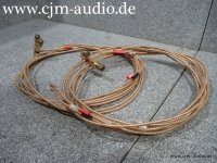
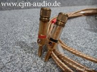
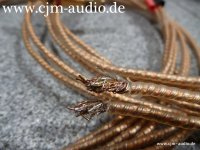
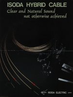
ISODA Speaker HB-55 HB55 Single Wire Cable - what other Option?

The cable from the attached images are already since a long time no longer available from currently manufacturing.
Sound quality very good in all respects.
What alternatives should one shortlist?

And a second question:
In what way is it best to make the connection to the plug
From my view image II seems to be a good approach but image VII not.

Thank you very much for advices.

P.S.: Here a description concerning ISODA cable (Audiophile n°36):
http://6bm8.lab.free.fr/Documentations/Revues/Audiophile/1977-1988/36/PARLE/PARLE.html

Attachments

  • ISODA HB-55-I.jpg
    ISODA HB-55-I.jpg
    117.8 KB · Views: 366
  • ISODA HB-55-II.jpg
    ISODA HB-55-II.jpg
    155.9 KB · Views: 359
  • ISODA HB-55-III.jpg
    ISODA HB-55-III.jpg
    133.7 KB · Views: 356
  • ISODA HB-55-IV.jpg
    ISODA HB-55-IV.jpg
    119.8 KB · Views: 351
  • ISODA HB-55-V.jpg
    ISODA HB-55-V.jpg
    109.7 KB · Views: 366
  • ISODA HB-55-VI.jpg
    ISODA HB-55-VI.jpg
    415.3 KB · Views: 333
  • ISODA HB-55-VII.jpg
    ISODA HB-55-VII.jpg
    315.6 KB · Views: 331
  • ISODA HB-55-VIII.jpg
    ISODA HB-55-VIII.jpg
    213.6 KB · Views: 387
  • ISODA HB-55 datasheet cover.jpg
    ISODA HB-55 datasheet cover.jpg
    339.9 KB · Views: 232

Please suggest the Crossover and Cabinet details for the combination of drivers Peerless HDS -P830990 & Vifa BC25TG15-08 for bookshelf

Dear All,

Can you share the cabin size and custom crossover details for the bookshelf with the following combination of tweeter (BC25TG15-08) and woofer (HDS -P830990 ) ?..

Attached datasheet of both drivers.

Please help me to find the best output.

Attachments

Hello from Barendrecht the Netherlands

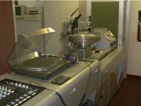
My name is John and I used to cut records during 2000-2003 in Rotterdam,I was trained for this In Miami by Aldo Busio and George Garcia.
Nowdays I'm a owner of self build JBL monitors and speakers and always in search for JBL 2225 speakers.
Hello to all members!

9-9-22 003.jpg

Attachments

  • johannes richter2.jpg
    johannes richter2.jpg
    156.5 KB · Views: 52
  • johannes richter3.jpg
    johannes richter3.jpg
    146.6 KB · Views: 50
  • soundstream 2003.jpg
    soundstream 2003.jpg
    186.8 KB · Views: 49
  • soundstream-2 2003.jpg
    soundstream-2 2003.jpg
    165.2 KB · Views: 53
  • apr18_01.jpg
    apr18_01.jpg
    249.2 KB · Views: 46
  • Apr18_06.JPG
    Apr18_06.JPG
    278 KB · Views: 46
  • Apr18_12.JPG
    Apr18_12.JPG
    277.8 KB · Views: 48
  • Apr18_19.JPG
    Apr18_19.JPG
    300.7 KB · Views: 55

HV Voltage ARC

My amp uses 2500 plate voltage. At start up I occasionally hear an arc, but cannot see it. Never blows a fuse. Once running no arcs. I have better than 1/4" in-between HV conductors except at each can capacitors that the aluminum case is not connected to anything and it has a plastic sleave with 1/8 clearance from ground. Caps have an 1/8" clearance from case with the 600 volt insulated wire on the negative leads only and each cap sees 325 volts. The can caps case is at least 1/8 inch from the grounded case. It uses a voltage doubler and eight 220uF 400 volt capacitors in series. Each doubler leg uses 3KV of diodes. The HV has a 1000pF 5KV capacitor to ground. PSDII shows less than 50 volts overshoot at start up. No chokes in HV circuit. I do not get it

The importance of Kms(X) and BL(x) for mid-ranges

edit: new discussion about issues related to drivers other than just only midranges;
https://www.diyaudio.com/community/...l-x-for-mid-ranges.376164/page-7#post-7703832

Hopefully this is the right subforum for this.

I have a question about the following,

So for loudspeakers there are basically three dominant factors creating distortion/non linear behavior.

  • The non-linearity of the compliance (1 / stiffness), Cms(x)
  • The non-linearity of the BL vs displacement curve, BL(x)
  • The non-linearity of the inductance. Le(x)

There are some other factors, like cone break-up, compression of air etc etc, but for now I am not going to consider those.

So the BL(x) and Cms are both dominant for the lower frequencies, around the Fs up to roughly 2 x Fs.
From that point on the inductance Le(x) is starting to be the more dominant factor.

So let's assume we have a mid-woofer with a Fs around 50Hz.
We are gonna cross this driver (actively) around 100-120Hz (2nd order highpass)

At this point, as far as I understand, it's not really important anymore how (non)linear the Cms and BL(x) is, since the Le(x) is dominant here?

As long as we keep the cone excursion to a minimum, which is most cases is fine since most speakers will run into there max power at this point with a cone excursion of just 1-3mm or so.
  • Thank You
Reactions: camplo

Hi from Australia

Hi all,
I came across this forum as I am trying to reproduce an amp that was found in an old arcade machine. Restoration of some of these old machines becomes difficult as parts like this just disappear into history. The work so far in getting the schematic together has been completed by others but it appears I am the first to attempt to actually build it. I thought it may be useful to have access to a resource like this forum in the attempt.
All of my electronics experience comes from arcade pcb repair so audio may be a bit of a mystery to me.

New to the group and in desperate need of Help

My name is Austin im new to the group and need some guidance im new to all of this so be easy on me, i had the bright idea of building a portable bluetooth speaker and just started ordering stuff on impulse with no plan or anything so i currently have 2 Grs 3” fullrange drivers 4ohm 20watts max and 2 6.5” polly cone midbass woofers from parts exspress there 40 watts rms i havent got an amp yet but question is can i use all of these speakers and make them sound decent if so what do i need to make thst happen cross over, filter or what ever id like to be able to just buy somthing pre assembled and throw it in cross overs just thinking about them gives me a headache or do I need to start from scratch and if so a good cheap combo of speakers that would make a decent bluetooth speaker with some decent bass thanks in advance.

Mark Levinson ML-9 recapping (1985)

Hello to all.

I've decided to recap my old ML-9 amplifier, which, I think, deserve it 😉

At the moment, I'm looking for 1) finding as much and well the same references than the original ones (which is a fancy yet uneasy job 😉 2) finding the right way (procedure) to replace the capacitors on the amplifier board (which seems uneasy too, considering the way it is built, as I'll explain).

I’m not a professional but I’ve got plenty of time, I already recapped several small amplifiers (like some Cyrus 1 and 2 and other electronic devices), and I’m equipped with all the necessary tools. But if it appears that it is impossible for someone like me to achieve the task, I’ll try to find a qualified professional to have the job done…

Then.

1. finding the same references than the original ones. Easy for certain items. Difficult or impossible for some others. Possible with a few references if you buy 10 or 300 of them (depending on the item). For instance, I’ve chosen to replace the original Sprague 36DX 36000uF/100V by new United Chemi E36D101HPN363UEM9N bought from M…r (same voltage/capacity/size) which, I believe, are widely used by Madrigal to recap old ML amplifiers. Those capacitors are not on the signal path and should do the job. Selecting Cornell or Vishay (Sprague) of the same type would have demanded that I take at least 9 of them, which is rather expensive.

I couldn’t find the 10/100V same polycarbonate caps (and as film caps I suspect they are not too bad even after 35 years of use), but I bought East German RFT NOS 10/100 polycarbonate caps, in case (they seem OK, cap 15uF and Vloss 2,5% - acceptable?). I could find NOS Sprague 39D series 520/100V caps, and I’ll check the Vloss and ESR when I got them. Hoping they are OK or that I could reform them if necessary. I could find NOS 10000/10 Frako (same question than previous). I could find new TE1105 250/6V at M…r.

Then I’m wondering what to do with the 672D Sprague 680/6.3V/105° which are used in the DCO suppressor circuit. If I’m not mistaking, they should be on the signal path. Impossible to buy less than 291 units… at 3,5/unit, I won’t do it. So I’m looking to find a substitute, but which? I found this: UPM0J681MPD6TD (UCC). Rippled current is at 825 mA which could match the particular position of these caps. But I’m fairly ignorant about this point (and many others…). A helpful advice will be happily considered 😉

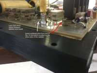
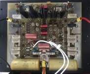
2. Assuming that I found all capacitors needed. The physical operation of replacing them has yet to be done. (!) Rather simple when access to the whole circuit board is open and clear. The power regulation board and the DCO board are in this case. BUT not the amplifier board, which is almost stuck to the large radiator, the transistors being on the outside of the radiator, their pins soldered on the inside of the board, where all the components are. A kind of sandwich, where to take out the board in order to have a full access to the soldering points of the components (the board seems to be a double sided board with different tracks on one side and on the other), you have to unsolder the 10 power transistors and un screw them. Which is a delicate job to do, especially when you see that some transistors pins are VERY close to some components. The pictures show this, I hope.

Then.
What to do? For the first part, advice is required for a suitable match for the two 672D Sprague 680/6.3V/105° in their particular location (DCO circuit).
For the second one, I haven’t taken everything apart yet, hesitating to do that at this point. Do I have to unsolder all transistors so I can have full access to both sides of the circuit board? Would it be necessary, would it be possible (even if not a proper job, I admit) to cut the leads of the existing caps and solder the new ones on them? (please don’t throw too many stones at me 😉. Or just unsoldering the defective (read old) parts and solder the new ones on place with enough welding to go through the hole (but not too much)?
I’m trying to understand how this was done by the manufacturer by observing carefully the board and it seems to me that at least the two 520uF Sprague Caps couldn’t be soldered before soldering the transistors… if this had been done, how could they have soldered the last transistor with so little space available? (but this is Mark Levinson and their techs are probably above the average humans about soldering).

Thanks for reading 😉 I'll be more than happy to read all of your comments and considerations!

please excuse my poor English and the quality of the pdf docs.

Attachments

  • ml-9 amplifier board and radiator.jpg
    ml-9 amplifier board and radiator.jpg
    615.3 KB · Views: 1,445
  • ml-9 amplifier board reduced.jpg
    ml-9 amplifier board reduced.jpg
    792.1 KB · Views: 1,955
  • ml-9 part DCO board.jpg
    ml-9 part DCO board.jpg
    807.6 KB · Views: 1,314
  • ml-9 regulation board.jpg
    ml-9 regulation board.jpg
    615.2 KB · Views: 1,372
  • ml-9 transistors_radiator.jpg
    ml-9 transistors_radiator.jpg
    808.8 KB · Views: 1,689
  • ML-9_schema-DCO Protector.jpg
    ML-9_schema-DCO Protector.jpg
    698 KB · Views: 1,323
  • ML-9_schema_amplifier board.pdf
    ML-9_schema_amplifier board.pdf
    136.9 KB · Views: 578

2SK240-Y

I was browsing an old electronic parts shop in my city when I accidentally spotted some 2sk240s with a grade I had never seen before. I was curious, so I picked up a few. I checked the Toshiba datasheet, but I couldn't find this grade listed. Do they really exist?

Thanks

Attachments

  • Screenshot_20230831-110341~2.png
    Screenshot_20230831-110341~2.png
    331.7 KB · Views: 232

Foster 100K03 PA speaker

Hi guys,

I'm only posting this as I thought these mildly interesting, hence I bought them.

These apparently came out of a church and I presume there were more as they have variable autotransformers to balance output and transformers for 100v line use. The hanging hooks suggest one was mounted horizontally and the other vertically.

The drivers appear like new. I can't tell whether the surrounds are stiffer than original, however, and have not yet measured Fs.

I haven't yet fired them up as the wiring has been played with.

Ignore my file name I know they hardly qualify as line arrays...

I'm not sure what to do with them, but one of the drivers may go to a table FM radio I'm making...not so thrilling I know! ...but after I've played with them with the autotransformer removed and wired in series/parallel to test them as is in the box.

Cheers

Stuey

Attachments

  • Foster Line Arrays.jpg
    Foster Line Arrays.jpg
    24.5 KB · Views: 114
  • Foster 100K03.jpg
    Foster 100K03.jpg
    23.8 KB · Views: 113

For Sale [ADL] Manzanita OB Air Core inductors

As above.
I have a set of air core inductors for the Manzanita OB outlined in the 'Fast, fun, Inexpensive OB project' thread.
Due to downsizing I no longer have the space I need for these speakers - so I shall move them on and pick a smaller project.

View the above thread, circa post 800-821 to see their origin. One of the larger inductors has extra turns 😉

A$150 for the set of 4. Would prefer local pickup as these guys are weighty, 2.3kg for the large, 0.6kg for the small, but will post at buyers expense within Australia if requested.

Attachments

  • IMG20240731103008[1].jpg
    IMG20240731103008[1].jpg
    411.5 KB · Views: 52
  • IMG20240731103017[1].jpg
    IMG20240731103017[1].jpg
    319.7 KB · Views: 52
  • IMG20240731103028[1].jpg
    IMG20240731103028[1].jpg
    374.9 KB · Views: 60
  • IMG20240731103136[1].jpg
    IMG20240731103136[1].jpg
    332.2 KB · Views: 60
  • IMG20240731103254[1].jpg
    IMG20240731103254[1].jpg
    323.2 KB · Views: 57

β22 Stereo Amplifier / Linestage Preamp/ HeadPhone Amp

A completed set of Beta22 amplifier and Sigma22 PSU that can be configured as a linestage preamp, a headphone amp and even a low power amp to drive sensitive speakers.
This amp is built as a 2 amps for stereo channels + 1 amp as active ground.

More information here:
https://www.amb.org/audio/beta22/

It is built on a backplane board :
https://www.amb.org/audio/epsilon22/
Hence the amp looks neat and sleek, will less wirings running all over the place.

Powering the amp is the Sigma22 regulated PSU:
https://www.amb.org/audio/sigma22/

Transistors, including the matched quad of 2SK170/2SJ74 per channel were bought from AMB LAB during those years when they were available at their online shop. Hence you can be assured that they are genuine. So there are a total of 3 matched quads of these precious FET in this amp.

This projected was built and tested, played without a chassis some time ago. I had the ambition of building a customised superb heavy steel chassis which did not materialise due to many distractions. Despite that it was commissioned to work, i do suggest that you read the information at AMB LAB, power up, test and monitor and trim the dc offset carefully.

A lot of effort and time has gone into putting this together using premium parts from legit /authorised sources.

I am asking for 420 USD (Shipping is covered).

150w or 200w PSU for Dayton KABD-430

Hi,

I want to assemble a small active 3 way speaker design and I will be using the Dayton Audio KABD-430 amp. which has an integrated ADAU1701 DSP.

https://www.parts-express.com/Dayton-Audio-KABD-430-4-x-30W-Bluetooth-Amp-Board-with-DSP-325-430

The idea is 2x 30W (tweeter and mids) + 1x 60W (woofer). I know it's not much, but these will be used in a small room with 4+ subwoofers.

The thing is that I need a power supply for the 120W of total power. Is it OK If I go with a 150W SMPS? Or it's recommended to go with 200W?
I am thinking in the LRS line from Meanwell.

Amp + DSP will be in a separate compartment from the SMPS.

Looking forward to your replies.

Arcade Amp power supply question

The background to this is that I am attempting to reproduce the amp in the schematic for an arcade machine restoration. These things are now quite rate and difficult to find.
You may note that in the power supply schematic there is a note that this schematic is for an amp running of a VAC toroid transformer but it was also built to run of 12VDC. Of course I need the 12VDC type. Given that I am guessing the coil referred to as replacing the bridge rectifier is an inductor or choke. My question is how do I work out the best value for this component. Power is comming in from a pretty basic switched PSU.

Attachments

  • CPB-001A.pdf
    CPB-001A.pdf
    95.6 KB · Views: 83
  • Screenshot_20240731_113703_Samsung Internet.jpg
    Screenshot_20240731_113703_Samsung Internet.jpg
    156.6 KB · Views: 75

Fractional Octave Filtering

One of the options in REW is for fractional octave filtering of the speaker response. Since the source code for REW is not available my question is does anyone know the formula or a link to the formula for fractional octave filtering of response data. I am trying to program it into code I am writing and cannot find an algorithm. For example is what is done is to apply a linear Gaussian filter using the log of the frequency data as an input? I can't think of any other way of defining a filter as a fraction of an octave. Also what is the most efficient way of implementing the Gaussian filter? I hope some of you have knowledge of these considerations.
Projects by fanatics, for fanatics
Get answers and advice for everyone wanting to learn the art of audio.
Join the Community
508,467
Members
7,920,913
Messages

Filter

Forum Statistics

Threads
407,832
Messages
7,920,913
Members
508,467
Latest member
AmcAmx