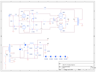
I still consider myself a newbie. I have put together a couple of amps, mostly monkey see monkey do. (no offense intended to the primates) I have put it together from scrap, used parts, and junk box parts. A PP 6L6 amp using a floating paraphase phase splitter, a 6SN7. Schematic attached. I'm a bit surprised that it starts to clip at just about 18 watts rms. I'm testing at 1 kHz, and yes, the output transformer was recovered from a 1940 RCA Victor floor standing phonograph/radio. But a "high end" one that had a PP 6F6 fixed bias amp, that claimed 19 watt. Any suggestions as to what I might have gotten wrong would be appreciated.
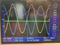
Amp is working sorta OK, especially given the low quality OPT. I am attaching a second image, which is a screen capture of my scope. Reminds me of when Polaroid Corp sold instant cameras specifically for Tek scopes. (Now you know how old I am). There are 3 scope traces: Blue and yellow are the output tube plates, violet is the output into an 8 ohm resistor load. I have fixed the imbalance in the magnitude of the two tubes, but I have not figured out what might be causing the "step" in the output waveforms, seen near the peak of the sin wave. Anyone seen anything like this before? Thx.
Amp is working sorta OK, especially given the low quality OPT. I am attaching a second image, which is a screen capture of my scope. Reminds me of when Polaroid Corp sold instant cameras specifically for Tek scopes. (Now you know how old I am). There are 3 scope traces: Blue and yellow are the output tube plates, violet is the output into an 8 ohm resistor load. I have fixed the imbalance in the magnitude of the two tubes, but I have not figured out what might be causing the "step" in the output waveforms, seen near the peak of the sin wave. Anyone seen anything like this before? Thx.
Attachments
Last edited:
I don't think that's all that bad for a cathode biased amp. with an undersized OPT.I'm a bit surprised that it starts to clip at just about 18 watts rms.
jeff
Last edited:

You're gonna need better outputs plus fixed bias (bias supply with adjustments) to get more output but you are doing good now....
The cathode bias for the 6L6s sits at 23 volts, no signal in. As I increase the drive from my signal generator, as the peak of the grid signal approaches 24 volts, the clipping starts. The current thru the 6L6s increases just a bit, driving the bias voltage up. I am watching with a scope and can see that the 2 grid inputs are tracking pretty well. How does one optimize the cathode resistor on the 6L6s? By my quick calculation the tubes are idling at 23/333 = 0.0691 /2 = 34.5 mA. Seems a bit low for a 6L6?
You did not say what the primary impedance of your 1940s output transformers are.
A push pull 6F6 with a 10k Output transformer puts out 11 Watts, GE tube book. Sorry I did not look up the old RCA book.
Suppose that your output transformer is 5000 Ohms plate to plate, and 8 Ohms secondary. That is a 25:1 turns ratio.
Example DCR for the primary of 250 Ohms.
Example DCR of an 8 Ohm secondary of 0.4 Ohms.
The insertion loss of my example transformer would be 1dB.
You got 18 Watts, Right?
1 dB more power at the primary, would be 1.25 times more power than the power at the output.
1.25 x 18 = 22.5 watts from the push pull 6L6; and then the insertion loss of the output transformer reduces it to 18 Watts.
Now, go and measure the primary impedance of your output transformers, then measure the primary DCR and the secondary DCR.
And refer the secondary DCR loss versus the load impedance on the secondary; I used 8 Ohms as an example.
It seems your amplifier is working well.
Have Fun!
The screen voltage is supplied through a 16K resistor. You got 10.75mA through it, and there is no reservoir cap, that's probably not enough for both grids at peak power, the screen voltage may sag. Can you check the screen voltage at max power?
jcalvarez,
Yes, check for any signal voltage on the screens.
But perhaps that has already been taken care of . . . 16k Ohms is sending current to the series string of Zeners, as well as to the screens.
Yes, check for any signal voltage on the screens.
But perhaps that has already been taken care of . . . 16k Ohms is sending current to the series string of Zeners, as well as to the screens.
That's my concern, looking at the datasheet example for a tetrode-connected push-pull. G2 current at max signal is 19mA. Not the same example as the schematic in #1, but I think close enough.But perhaps that has already been taken care of . . . 16k Ohms is sending current to the series string of Zeners, as well as to the screens.
CORRECTIONS: I do have a 40 MF capacitor to ground attached to the top of the Zener string, filtering the ~260 volt source. I also have 150 ohm series resistors connected to each G2 on the 6L6s. Lastly, I called it a 6L6 amp, they are actually 6BG6. It's noted on the schematic. They can be had for nearly pennies, they have, I believe a higher voltage rating, and at least for some manufacturers the innards are identical to the 6L6. I will fix the schematic and re-post.The screen voltage is supplied through a 16K resistor. You got 10.75mA through it, and there is no reservoir cap, that's probably not enough for both grids at peak power, the screen voltage may sag. Can you check the screen voltage at max power?
I took some measurements of the output transformer so I would better know what I am working with. At low levels, 1 kHz 21.6 volt p-p input yielded 0.648 volt p-p out. N, turns ratio then is about 33.33 : 1. If I remember correctly the impedance is ratio N^2, so about 1111. 8 Ohm load on the secondary "appears" as ~9000 (8888) Ohms, plate to plate. Seems about right? Also I measured the primary resistance is 576 ohms, 13.4 Henry, the secondary is ~0.5 ohms, 12 mH.You did not say what the primary impedance of your 1940s output transformers are.
A push pull 6F6 with a 10k Output transformer puts out 11 Watts, GE tube book. Sorry I did not look up the old RCA book.
Suppose that your output transformer is 5000 Ohms plate to plate, and 8 Ohms secondary. That is a 25:1 turns ratio.
Example DCR for the primary of 250 Ohms.
Example DCR of an 8 Ohm secondary of 0.4 Ohms.
The insertion loss of my example transformer would be 1dB.
You got 18 Watts, Right?
1 dB more power at the primary, would be 1.25 times more power than the power at the output.
1.25 x 18 = 22.5 watts from the push pull 6L6; and then the insertion loss of the output transformer reduces it to 18 Watts.
Now, go and measure the primary impedance of your output transformers, then measure the primary DCR and the secondary DCR.
And refer the secondary DCR loss versus the load impedance on the secondary; I used 8 Ohms as an example.
It seems your amplifier is working well.
Have Fun!
How did you calculate the insertion loss in your example above? I understand transformer efficiency, and might even be able to measure it. Google is my friend, so I have been told. (-;
wstein25,
Example:
Consider for the moment, where all the insertion loss is in the primary DCR.
If the design is 5000 Ohm to 8 Ohm, the turns ratio is 25:1. [Right? (Ratio of Turns) squared = impedance ratio].
The wire is too thin, so the DCR is 600 Ohms.
That gives us a voltage divider in the primary of 5000/(5000 + 600) = 0.893
0.893 of the applied voltage is "in the turns", the rest of the voltage is in the DCR.
That is just like a Lumped Value resistor of 600 Ohms in series with the turns.
Power is according to V squared: 0.893 x 0.893 = 0.797 of the power is "in the turns"
We have lost 0.203 of the power.
At 20 Log of 0.893 of the voltage, we get -0.983 dB, about -1 dB
Thicker wire:
If the DCR is 300 Ohms, we will have 1/2 of the loss of the 600 Ohm DCR.
300 Ohms, -0.5dB
In the same manner, if the 8 Ohm secondary has 0.48 Ohms DCR, we have another loss, -0.5dB
-0.5 dB in the primary, and -0.5 dB in the secondary, we have a -1 dB total loss.
-1dB is a power loss; 0.794 of the total power from the tubes.
10 Watts x 0.794 = 7.94 Watts
All the above has some error, because the primary is 5000 Ohms plus 300 Ohms is 5300 Ohms,
and the 8 Ohms plus 0.48 is now 8.48 Ohms.
The idea is to find the approximate minimum insertion loss of the transformer at midband frequencies.
Laminations loss, etc. are not included in the estimate, your loss may be larger; but you will be in the ballpark.
Look at the screen voltage - is it dropping in sync with the output? you have 10 mA available, data sheet says 19 mA average just short of clipping
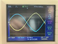
I put the scope on the screen, I get about 260 VDC, with a barely measurable ripple of about 20mV. Here is something to note. The tubes are unbalanced and the step seems to align with the opposite tubes peaks. See attached scope capture. Should I be trying to balance the tube's output, and what would be the best (or easiest) way to do that? I did trimming to adjust the phase inverter's output to be equal. Perhaps it would be better to trim the phase inverter output so that the output tubes are balanced?
Attachments
wstein25,
Either fix the unequal balance of the output stage,
OR,
Set the phase inverter balance to cancel the output stages un-balance,
Or
Live with the 2nd Harmonic distortion . . . you may, or may not, like the sound.
To fix the output stage poor balance:
Schematic in Post # 1 has both output tubes cathodes connected together, and they are connected to a single common self bias resistor & bypass cap.
Try using individual self bias circuits, separate the cathodes, and use two 680 Ohms and 100uF self bias networks, one for each cathode.
Measure the new individual bias voltages.
If the self bias voltages are not nearly equal, the tubes are poorly matched.
Unequal currents in the output transformer primary halves causes early saturation of the laminations.
Note: if the plate currents are unequal when you modify for individual self bias; then the plate currentsw were also unmatched with the original single self bias resistor and cap.
your output transformer did not like it, no matter which self bias, single or individual that you use.
For information about alternative circuits (do not do this if you do not have a signal source with XLR balanced outputs):
My latest mono-block amplifiers have balanced XLR inputs (The phase inverter is "in" the XLR CD player).
I use Very Well Matched 5881 output tubes, so well matched, that I can use a Single common self bias resistor without a bypass cap.
(many are fans of finding ways to get rid of that self bias bypass cap . . . I did . . . without using LEDs, Zeners, or CCS).
A CCS plus no bypass cap, limits the outputs to class A (less power out).
A common self bias resistor allows the outputs to transition to Class AB (more power out).
Last edited:
I separated the cathodes, each now has 500 ohm paralleled with 120 uF. On one of them I put a 50 ohm pot in series to allow for adjustment. They are now balanced to within about 0.1 volt across the 500 ohm cathode resistors. 21 volt/500 = 42 mA in each tube. This did not get rid of the step that happens near the peak. Just casual listening, with some types of music the distortion is noticeable. I may just have to pony up for a better OPT if I want to improve on this much more.
but I have not figured out what might be causing the "step" in the output waveforms, seen near the peak of the sin wave.
Hi @wstein25 you have done well!
As regards the step, it may not be the output tubes making this?
Its possible that it is getting in from somewhere, have you checked the input from your signal generator on the scope? Also have you had a look at the Grids (pin 5) of the two 6BG6 tubes?
It could also be some sort of high frequency oscillation that gets going for the 6BG6 tubes? (unlikely). High frequency not seen by your scope.
It could be a breakdown at high voltage?
I don't know the sense of which tube is which let's say the worst "kink" get's transformer coupled into the other tube so alternately tubes are producing the kink when Plate voltage gets high? Some sort of bias problem?
So the kink only occurs once per cycle per tube but it appears to be twice per cycle per tube but its not - its transformer coupling. So the kink is voltage dependent.
Find out if the full kink happens when the Plate is reaching maximum voltage or when the Plate is reaching minimum voltage. Maybe the Plate is getting too low and hitting Ground?
Have you checked what's happening on the 440 Volt and 268 Volt lines. Is the screen voltage stable? Try triggering the scope on a 6BG6 Plate and looking at the power supply lines with the other probe, look for that kink.
PS the HT B+ power supply is a voltage doubler and the capacitive decoupling is minimalist - wouldn't be surprised if you are getting 50Hz and 100Hz hum.
The 268 Volt line only as a 40uF capacitor to hold it up, the 16K resistor can only provide 10mA - its probably OK but worth a look.
Be careful stay safe with those high voltages.
Attachments
Last edited:
- Home
- Amplifiers
- Tubes / Valves
- Help with a 6L6 PP design