Peavey Triumph 120 Head Keeps Blowing F4

What could cause F4 to keep blowing? PT orange secondary seem okay with 2.8 ohms resistance end to end.

This circuit controls power lights and channel switching. Happens with or without footswitch connected.

Schematic attached. Woops, schematic is too large to upload. Available at https://www.thetubestore.com/lib/thetubestore/schematics/Peavey/Peavey-Triumph-Schematic.pdf

Thank you.

Attachments

  • 20240721_105549.jpg
    20240721_105549.jpg
    337.8 KB · Views: 69

Class AB Amplifier heatsinking size referenced to a pure class A amplifier

I`m wondering looking at a FEA simulation the heatsinking size of a Pure class A is accurately estimated by giving constant power dissipation and right thermal conductivity constants and we do get perfectly right with tolerance of +/-0.5 deg C when data is given properly.

Now consider a following example. I have a heatsink with which a constant power dissipation is made of 50W with mosfets on it. Then the heatsink temperature raises 15 degree above room temperature of consider 35 degree C to heatsink temp 50 deg.

Now consider the same heatsink how much it can dissipate when it comes to class AB where the idle current temp of heatsink rose by just 3deg C in AB mode. Now what I would like to know is that how much Class AB heat does the heatsink takes up for same AB.

SE 6SN7 & 7591S amplifier

I am building a valve amplifier, single ended, no feedback, triode-connected 7591S amplifier. For driver valve I am using one 6SN7. The schematic I am planning to use is based on Mikael Abdellah's KT88 amplifier and looks like this:
schematic 7591S.JPG

But I am unsure about the values on most components.

The things that are fixed: the tubes, output transformer and B+. Everything else is subject to change.

Thoughts? Tips? 🙂

Hey from WillBrettDesign

Hey everyone!

I’ve been lurking in these forums for a while as there is endless valuable knowledge, and I’ve finally gotten around to actually joining.

I’m a product designer by trade and I’ll be the first to admit not the most knowledgeable when it comes to science and engineering behind speakers but eager to learn more over time.

I’ve built quite a few projects around speakers and audio, some not so good others surprisingly great!

My latest project is a 3d printed transmission line 2 way speaker. I wasn’t expecting fantastic results but I must admit these do actually sound brilliant.

https://willbrettdesign.co.uk/transmission-line-speakers/

If you fancy taking a look and have any questions or feedback let me know. I’m currently working on improvements to the design of these.

Thanks

Will

hpbuilder introduction

Good evening to all! I join diyaudio to learn how to rebuild existing loudspeakers and share my knowledge about building loudspeakers from scratch. Currently rebuilding Infinity Kappa 9 loudspeakers and will require advice from members. So far I have built open baffle, h-frame and closed loudspeakers. I have also modified a 3-way loudspeaker to active crossover with satisfying results. My mother tongue is french and I may express myself in odd ways. Thanks for letting me in!

AI-Assisted DJ Monitor Design Concept: First Build. Seeking Some Guidance from the Experts

Hey everyone,

I'm new to the forum but have been diving quite deep into speaker design resources, including this awesome community! I've been soaking up knowledge from your posts, YouTube tutorials and to kickstart my first build, I've been experimenting with some AI help to develop a concept. I'm eager to get your expert feedback—always good to have a human reality check on those AI ideas! 🙂 This will be my first proper speaker project, though I did build some basic car speaker based boxes with my dad when I was a kid.

My Goal: A versatile DJ monitor system that can handle both home listening and small house parties with powerful bass, clear highs, and the flexibility to switch between sitting and standing listening heights.

Main Challenges:
  • Balancing relatively compact size with the ability to deliver impactful low-end for electronic music genres.
  • Being able to cover a wide listening area and fill a room of around 25m2 with sound.
  • Have a modular system where the top's can reach low enough to be used on their own.
The Solution:
  • System: 2 x 2-way closed top boxes + 2 x ported subwoofers
  • Amplification: Hypex FusionAmp FA253 with built-in DSP (easy plug & play DJ mixer)
  • DSP Presets: Flat, Warm (for tops only), and Subwoofer Integrated
  • Target Tuning Frequency: 45Hz (tops only), 25-30Hz (with subs)
  • Sound Signature: Primarily flat, with a warm DSP option for versatility
  • Aesthetics: Inspired by the clean and modern designs of Newfidelity J.J 8.1 and Ojas speakers. (see inspiration below)
Components Under Consideration (data sheets and vituixCAD models added below):
Cross-over points:
  • Subwoofer to Tops (80-100 Hz)
  • Mid/Bass to Tweeter (2-3 kHz)
Why Not just buy off-the-shelf PA or Studio Monitors?
  • PA Systems: Too bulky, aesthetically unappealing for home use, and often lacking in high-fidelity sound quality.
  • Studio Monitors: While sonically impressive, they typically lack the loudness, bass extension, and wide dispersion needed for the intended use.
Mounting Flexibility:
  • Direct stacking on the subs for seated listening. (Probably will use them in this position most of the time)
  • Distance rods for standing DJ monitor height.
  • Wall/ceiling mounting as a potential future option.
Questions I still have:
  • Does the driver selection seem well-suited to the goals?
  • Will this amplifier work well for this idea? (Is matching 4 ohm and 8 ohm drivers a problem?)
  • I've used subtle low shelf filters in the VituixCAD models to extend the low frequency range a bit. Is this similar to what is possible within the Hypex Filter Design software?
  • Any concerns about the waveguide choice? (if so, what would be better options?)
  • Any other suggestions or alternative components worth exploring?
Next steps
  • Check your feedback 🙂
  • Detailed design of cabinets in Sketch Up
  • Learn more about the Hypex Filter Design software
  • Build cabinets

I'd love to hear your thoughts on this concept. All insights are welcome!

Here are some first simple sketches of the system:


Seated

Sit.png


Standing
Stand.png


12" - Subwoofer model VituixCAD


12 inch Scan Speak Model.png


8" - Closed top model VituixCAD
8 inch Scan Speak Model.png


Inspiration

Inspiration.png

Technics SU-V550

Good day all,
I need some advice please. I have a Technics su-v550 and the record switch flexible flat cable that goes to the switch on the pcb is broken. I want to replace the switch and cable with a rotary switch. Will a 4 gang/ 6 contact per gang rotary switch do the job ?
Advice appreciated.
Regards
Jan
Guy's, here is a better layout of the original switch, which rotary switch will work, is a 4 gang up to the task ?
Thanks

Attachments

  • Screenshot 2024-07-24 120326.png
    Screenshot 2024-07-24 120326.png
    179.4 KB · Views: 76
  • Screenshot 2024-07-24 120658.png
    Screenshot 2024-07-24 120658.png
    46.2 KB · Views: 62
  • Screenshot 2024-07-24 123513.png
    Screenshot 2024-07-24 123513.png
    29.8 KB · Views: 58
  • Screenshot 2024-07-24 173024.png
    Screenshot 2024-07-24 173024.png
    62.2 KB · Views: 52

Ian Canada Fifopi Q3

I have a problem with my FifoPi Q3 Ultimate. i know it's an old version but that does not mather to me. The thing is when i connect the board every PSU that i connect gets's bloody hot, the reg and the rectifier bridge. And the wifi dongle will not start. And Ropieee wil not start also, no IP adress.

It looks looks like there is some kind of short inside the FiFoPi. And one of my RPI's looks dead because of it.

When i disconnect the FiFoPi and use the RPI alone, the dongle works again, IP and Ropieee are back and all works fine.

I think this is beyond repair, or not?

Beresford TC-7533 Hi-Fi DAC & Headphone Amplifier

Excellent condition.

Specs:
  • 4 Digital Inputs (S/P-DIF - 2 optical, 2 coaxial)
  • 1 Analogue Outputs (Cinch - fixed)
  • Headphone Amplifier (6,3-mm-Jack) with Volume Control: 12 to 600 Ohm, 700mW
  • Frequency Response: 20 Hz to 20 kHz
  • Signal-to-Noise Ratio: > 103 dB
  • Channel Separation: > 100 dB @ 1 kHz
  • Total Harmonic Distortion: < 0,0015 % @ 1kHz
  • Resolution: up to 24 bit
  • Sample Rate: 28 to 192 kHz
  • Burr-Brown Converters
  • LED Indicator for chosen Input
  • Colour LED for On-/Off-Switch
  • Direct Current Sink: Device can be used worldwide
  • Gold-plated Connectors
  • Solid, Black Metal Case
  • CE certified
  • Valuable Switching Power Supply (12 Volts DC) included
  • Dimensions: 180 mm × 140 mm × 50 mm


Price: 150 euro

========

Will be shipped securely.

Location: Sofia, Bulgaria
Contact me here or by email: veselin.karavelov@gmail.com

Vb > Vas vented box

Hi!

Maybe this is a simple question but I didn't find exact answers for it.

So what if the net volume of a vented box is greater than the Vas value of the driver? I know that such a box is generally recommended if Qts is over 0.4, but what if we have, say, 0.3 Qts? In the case of such low Qts, in most cases a smaller box than Vas is recommended. But why? Of course we can see the result on a simulation, which will show an early drop towards the bass and an emphasis at the vent tuning frequency.

So that's all (pretty much)? If we correct the frequency response (say with DSP), do we get a sound as if we had a box that gives such a frequency response in the first place? Of course, taking into account the tuning frequency. If so, where is the limits?
I ask because a larger box has certain advantages (over smaller ones) that could be used this way.

Add.:
I have read several times on this forum that the loudspeaker 'pioneers' established an (in their opinion) optimal Vb/Vas ratio for bass-reflex boxes, and this is Vb = Vas/1.44 if the damping of the driver is adequate (Qts at or below 0.4 if I remember correctly). What is it about this ratio that made the pioneers choose it?
What if we use Vas × 1.44 (and correct the frequency response with DSP) instead?

Tweeter Morel Supreme ST 1048 vs Mundorf AMT19CM1.1C

Hi,

Many years ago I have build a loudspeakers with these speakers:

//
Tweeter: Visaton KE25SC (8 ohm) in ceramic
Midrange Visaton DSM 50 FFL (8 ohm)
Woofer: Monacor SPH250KE (kevlar)
//

after some crossover update and many measurements, now I'am happy with the final result and I think will stay with me for several years (hopefully for life).

In the next years I I plan to design more speakers for another system but more expensive , and for this reason I should choose higher level speakers.

About the woofer and midrange I think to be in the right way with: Seas L26RFX/P (8 ohm) (woofer) and Scan-speak 12MU-8731T00 (8 ohm) (midrange).

Also I have never heard of them being fairly well-known brands I hope it is a good choice.

Instead, the most difficult choice seems to be the tweeter.

This is because I would like something better than the good Visaton KE25SC, and the choice does not seem easy, since few tweeters are 8 0hm.

So I was thinking of choosing either the Mundorf-AMT19CM1.1C or the Morel Supreme ST 1048, and I am wondering which one is the better choice.

Someone have has any experience with these tweeters ?

Which one do you recommend ?

Thank you !!

Mikael Abdellah's KT88 SE amp ... Changing input tube from 6n1/6n2 to ecc83/12ax7

Hi all

Newbie here.
Have picked up a Mikael Abdellah's KT88 SE amp build.
The builder made the speaker outputs with RCA plugs instead of binding posts so I am sending it off to a tech buddy to change these out.

My question is .. Shall I get him modify and change out the input tube to accommodate an ecc83/12ax7 tube?
I have a great selection of ecc83/12ax7's in my collection so would be better for experimentation without buying a bunch of other tubes.
Is the 6n1/6n2 sonically better and should I stick with it?

Cheers in advance.

Niz
New Zealand

Boston Acoustics HPS-10SE repair

Hello everyone,

Got a Boston Acoustics HPS-10SE I'm trying to repair. Got it all pulled apart and immediately noticed the nasty glue over everything, so have spent time removing that. The NP caps on the Class-D board were toasted, so replaced those. Also replaced the couple power transistors with equivalents (TTA004B, and TTC004B) on the main board, and the two caps on the +-15V outputs (C05 and C06), but, continues to not work. Sadly it was doing the same thing before both of these "throw parts at it" options. With the class-D attached to the amp board, I can physically hear the NP caps resonating =( and they get quite hot. With the Class D uninstalled from the board, but the pre-amp board hooked up, the positive 15V rail power transistor (Q01) gets quite toasty and seems to go into thermal shutdown (the positive rail craps out). With the pre-amp board unattached, all the power rails seem good and solid. So either the preamp board has a fault, or it doesn't like the class-d being unattached.

The service manual, which includes the schematics for all but the stupid "proprietary" Class-D board is attached (it's freely available from the BA website if you login). I'm not sure how to troubleshoot this tbh since it wants to fight me doing it piecemeal. Maybe hook external +-15V to preamp board and see what it does?

Attachments

Reliability of salvaged output transistors?

Hello,

I am trying to buy lateral mosfets for my next amp projects but since they are obsolote devices i was not succesful. I could probably buy a set of them if i visit enough shops around also with very inflated prices.

Other option is Exicon devices which i would normaly prefer but purchasing them from profusion is not appeling due to high shipping prices.

So the thing is, i came across a used PA amp in local ebay equivalent. It is a beefy amp with 12 pair of Hitachi 2sk135/j50 laterals, a toroid transformer probably 2KVA range and other stuff found in PA amps. Seller is claiming amp is working and in good condition other than cosmetic issues. With a price of approx. 150 usd it attract my attention. But the question is;

Do you trust 30 year old transistors which probably worked in harsh conditions?

For Sale PAIR of Dayton Audio 10" Professional Neodymium Woofers with Free Shipping to US & Canada

I have a PAIR of Dayton Audio 10" Apollo Neodymium Woofers for sale.

Almost brand new - Purchased in June 2023 form Parts Express

Features:
Model Dayton Audio 10MB250N-8
250Watt Power Handling capability
Powerful Neodymium motor - BL of 19.2 !
High Sensitivity of 96.5 dB / watt
Cast Frame
Copper inductance cap for low distortion
Paper cone and cloth m-roll surround
2.5" Inside/outside wound copper voice coil on fiberglass former
Under spider and rear periphery venting
8 ohm impedance

$149.00 USD each @ Parts Express

Selling the pair for $175.00 USD with Free Shipping with Tracking Number / Shipping Insurance

Attachments

  • 20230801_170438 (1).jpg
    20230801_170438 (1).jpg
    501 KB · Views: 139
  • 20230801_170449.jpg
    20230801_170449.jpg
    521.6 KB · Views: 138
  • 20230801_170500.jpg
    20230801_170500.jpg
    382.7 KB · Views: 137

Which bass characteristics do you prefer?

I’m talking about closed enclosure tuning. Assume we’re going to design the three-way speakers utilizing a 12” woofer per cabinet. And the purpose is to obtain emphasized bass frequency (heavy bass speakers based on closed box configuration). Which way would you go for?

A) using high Qtc enclosure design, above 0.8 up to 2, and no attenuations on mid/high drive units (0dB)
B) using low Qtc enclosure design, below 0.58 down to 0.5, and employing some attenuations on mid/high drive units (such as -3dB to -6dB)

What are pros and cons between A) and B)?

A simple and easy Dielectric-Absorption evaluator, the D.A.-Boy

Hi there,


Here is another cheap & cheerful (and useful!) project: a dielectric absorption test-set.

What is DA (dielectric absorption)?

In a nutshell, DA is a parasitic effect affecting dielectric materials, and the capacitors they are made of.
Any real capacitor can be modelled as an infinite series of RC circuits.
In "good" capacitors, the first RC's total a large capacitance, and similar series resistances, resulting in an ideal cap in series with the ESR being the // sum of elementary R's.
Higher order effects are essentially minimal, and all of the losses are concentrated in the ESR, or the Q, the tan delta, the parallel damping resistance, .... etc: all these parameters are perfectly equivalent, and can be mathematically converted into any other one.
DA is somewhat different: although it counts as losses as it is a dissipative process, its real impact is absolutely minimal.
For example, mica is infamously known as one of the worst dielectric regarding DA, yet its losses remain very low.
This is the reason why this particular loss process has received a special treatment.
Although the energetic impact is minimal, the effect on the signals is far from negligible.
In dielectrics affected by DA, the elementary RC's of the series decrease more slowly, meaning a significant part of the total capacitance is hidden behind large R's, and large RC time-constants.
In practice, this means that when you attempt to charge or discharge such a cap very quickly, the farthest caps remain unaffected, and change the voltage and current after the event.

This delayed response leads to a host of unwanted effects, sometimes difficult to identify or attribute.
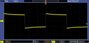
Some examples: the LF capacitance is larger than the HF one, sample-hold circuits show a small drop just after the sampling pulse, ramp generators have non-linearities, characterized by an excessive rise after the reset pulse, higher amplitude up to 50%, and lower amplitude afterwards.
It causes inaccuracies in the response of filters and equalization networks.
If you had the misguided idea of building a high-accuracy RIAA network from precision mica capacitors, the LF response would deviate from the ideal, even if you use 0.25% caps and 0.05% resistors.
In pulse circuits, it increases the settling time, in video signals, it causes streaking and lagging effects, and disrupts the black level, etc.

What causes DA?

The base dielectric material plays a major role, obviously, but many other factors also have an effect.
The presence of heterogeneities in the dielectric is an important one.
They can be discrete, like multi-sheet or multi-dielectrics caps, macroscopic as in layered materials like mica or granular materials like ceramics, or microscopic at the molecular level.
The presence of bubbles, voids, impurities, inclusions, wrinkles, fractures or other imperfections in the dielectric greatly increases the DA.
This means that composites, like PCB materials generally have a large DA.
The construction of the capacitor is extremely important: PP or PS are excellent dielectrics in theory, but a poor construction can totally ruin a capacitor based on these dielectrics.
Capacitors from the same production batch, in perfect condition, can display significant DA characteristics differences, even when all the rest is nominal.
DA is not systematically tested, but it is a good indicator of the quality and consistency of the production, as it is very sensitive to to the slightest contamination or deviation.

How is DA measured?

The universal method is to charge the CUT to a known voltage, keep it charged for a soaking time, discharge it briefly, let it recover completely disconnected, and finally measure the recovered voltage.
The ratio of the recovered voltage to the initial voltage is the DA value.
In this process, absolutely everything counts and influences the end result.
The only way to reproduce a result is to use strictly identical conditions.
Most accepted methods use time-scales of minutes or tens of minutes, and use mercury-wetted relays and similar devices.
Not very convenient for a fast, casual use.

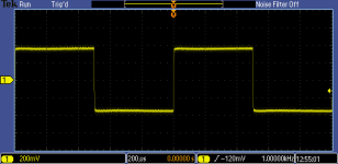
The evaluator I propose does things more simply, but more importantly, it does so at a (comparatively) blindingly fast speed: the total cycle time is 1 second, and although the reading needs a little longer to settle, it is still tens of times faster than any "official" alternative.

What is the value of such an accelerated measurement?

Basically, it indicates DA when it is present and the parameters of the circuit have been tweaked to mimic "standard" results (remembering that there are in fact no such standards, it just follows the mainstream trend).
If you build the tester, you will have your own, stable reference, and if you test a number of known samples, you will get a feeling of what a good DA is.
If other DIYers build the same instrument, you will be able to compare your results with others.

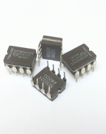
The circuit is simple and cheap, based mostly on commodities except for the opamp, which is not especially rare or expensive and can easily be substituted.

I propose two versions: one is adjustment-free and has no bells and whistles like a low-batt. indicator, the other has compensations and adjustments to improve the absolute accuracy.

The evaluator will work from 1nF to 10µF without needing to switch anything, and has two ranges: 1% full range, and 10% full range.
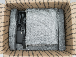
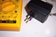
It is designed as a multimeter add-on, and plugs into the standard 3/4' spaced input ports of most digital multimeters: mains plugs and outlets use the same standard, meaning the tester is housed in the shell of an AC/DC wallwart.
The "luxury" version includes a small galvanometer, allowing a stand-alone operation.

The sensitivity is sufficient to distinguish between two slightly different flavors of PP caps.

The 10% range is sufficient for reasonably good caps: PP, PS, PET, PC, ceramic COG or X7R.
It is insufficient for high-k ceramics, Ecaps, bad paper caps, but you don't need a tester to be aware of that.
If you really need to know the details, you can add a range having a lower gain.

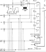
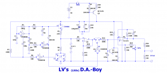
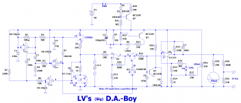
This is the "light" version:

attachment.php


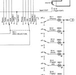
And this is the full one:

attachment.php


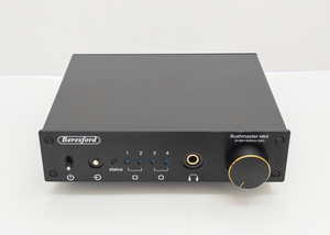
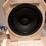
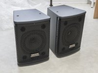
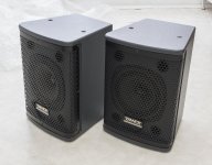
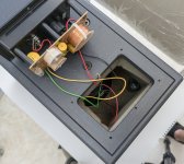
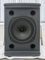
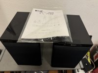
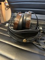
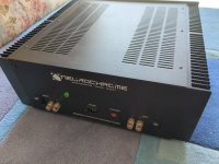
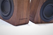
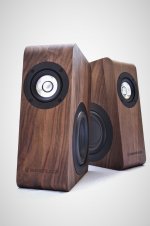
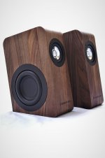
This is how my build looks:
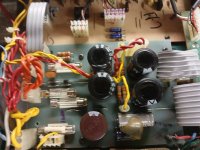
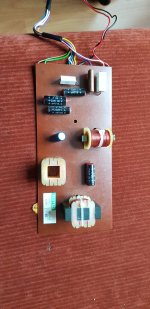
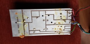
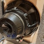
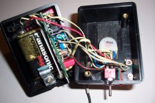
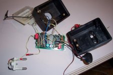
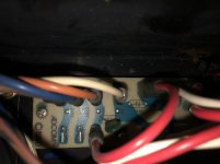
attachment.php


attachment.php


attachment.php


A look inside:

attachment.php


attachment.php

Attachments

  • DAlittleboy.png
    DAlittleboy.png
    56.2 KB · Views: 863
  • DAbigboy.png
    DAbigboy.png
    67.1 KB · Views: 858
  • DAboy1.jpg
    DAboy1.jpg
    223 KB · Views: 833
  • DAboy2.jpg
    DAboy2.jpg
    281.4 KB · Views: 802
  • DAboy3.jpg
    DAboy3.jpg
    253.2 KB · Views: 791
  • DAboy4.jpg
    DAboy4.jpg
    345.8 KB · Views: 784
  • DAboy5.jpg
    DAboy5.jpg
    274 KB · Views: 789

For Sale SSM2018P Obsolete ADI Voltage Controlled Amp Chip

I have some of these which I am not going to use. "Voltage Controlled Trimless Amplifier" 16 pin DIP.

$8 each. shipping varies by location. Limit of 4 pieces per customer. (This is a fraction of the price seen for parts from China on Ebay)

Datasheethttps://www.analog.com/media/en/technical-documentation/data-sheets/SSM2018.pdf

Attachments

  • SSM2018.jpg
    SSM2018.jpg
    95 KB · Views: 47

DBX 2231 EQ - Equalizer Op Amp Rolling

I have a dbx 2231 EQ that I use to tune a home HiFi system to a Harman curve at my listening position using REW. I bought this having seen the results of testing and a favorable review by ASR, and I’ve found that I presently prefer this to the DSP route that I used previously. Powered by a filtered conditioner and using balanced connections, this EQ is dead quiet in this system and I have noted no perceptible degradation in signal integrity, separation, or soundstage.

That being said, having observed audible improvements made by various discrete class A op amps (e.g. Sparkos, Burson, etc.) in the output stages of DACs, that makes me curious if op amp rolling may have an effect in this EQ. The architecture employs (4) NE 5532s on the input and output stages, and (32) NJM 4560s in the constant Q bandpass filters. One might speculate as to why these particular op amps were used, certainly cost was a factor, and I’m surprised the filters aren’t the 4560DD low noise versions although no noise is apparent, not audible noise anyway.

Having both newer Sparkos and Burson discrete op amps on hand, I felt this may make for an interesting exercise. I asked Andrew Sparks for his opinion, and he suggested trying the output and input parts first. Swapping the four NE5532s on the inputs and outputs involves just a bit of effort on my part to remove the four solder-through NE5532 ICs and replace with DIP8 sockets that I have on hand. On the other hand, swapping all those filter op amps for discretes would be prohibitively expensive even if the PS were up to it, and I'm not as optimistic that newer IC op amps would justify the hassle of swapping all those NJM 4560s, even for experimental purposes, although I found one person who did this about 10 years ago.

Any thoughts, intuition, hallucinations, etc., on this subject are appreciated.


dbx 2231 Face.jpg
dbx 2231 Internal.jpg
dbx 2231 Filter Op Amps.jpg
dbx 2231 IO Op Amps.jpg
  • Like
Reactions: geoturbo

Design errors in commercial equipment

Hi all,

While repairing equipment, I sometimes find design errors in commercial equipment. (That is, a cynic might say the circuits are designed to fail after the warranty expires, but I take the optimistic view that they are errors.) Please add your own known design errors to the thread.

Philips FR675:
Each channel has a 2SC2240 transistor that is used as a current source of about 9 mA to 10 mA having almost 50 V across it. That gives a power dissipation of some 400 mW to 500 mW, while the 2SC2240 datasheet states an absolute maximum power of 300 mW at 25 degrees C. The 2SA970 that is used as a degenerated common-emitter stage has the exact same problem: 400 mW to 500 mW in a 300 mW transistor.

Technics SU-VZ320:
The freewheeling diode across the 24 V relay coil is a Panasonic MA165, which is rated for 35 V. The relay coil is supplied from an unregulated -42 V supply via resistors that form a voltage divider with the relay coil's resistance. Due to the relay coil's inductance, the poor old 35 V diode is subjected to the full 42 V for a few milliseconds during turn on.

Early versions of the DATEQ BCS200 mixing console:
The gates of the P-channel JFETs that select the audio for the monitors are pulled up via indicator lamps. When a lamp burns out or loses contact, the JFETs can turn on and off randomly depending on PCB leakage current. It has been fixed in later models by connecting resistors in parallel with the lamps.
The resistors in the second-order 20 Hz/80 Hz Sallen and Key high-pass filters in early versions of the DATEQ BCS200 mixing console are swapped, resulting in a very low Q and very gradual roll-off. It is corrected in later models.

Sony TA1150:
As shown in this thread: https://www.diyaudio.com/community/...am-unsure-how-to-proceed.412059/#post-7667649 , the bias trimming potmeters are connected such that the quiescent current goes through the roof instead of to zero when the wiper loses contact.

Regards,
Marcel

DIY from the remains of Tandberg 3026A

Well,

This was one of the best solid state amplifiers from that time which was 30 years ago. TOTL from Tandberg, who's folks went on to work in and or found Electrocompaniet, Dynamic Precision, Hegel.

I have finally given up hope on it. The mistake was that I somewhat accidentally connected the high level positive outputs because I was "bi-amping" a two way speaker with each channel (was experimenting with DSP filters and direct connection to the amp), but didn't remove the positive jumper/bridge as I should have, but instead removed only the negative which makes no sense in retrospect. That's how I burned the right channel. It played, but only for a couple of minutes. Left is still functional. I tried replacing the resistors that burned, but the problem persisted. I replaced all the shorted transistors, but the resistors are still heating up and somewhere there is too much current where there shouldn't be. But I'm out of ideas.

That's why I want to salvage what I have which is the power supply, the heatsink and the box, the Elna power supply capacitors (two 80V 15k uF each) and make a DIY amp perhaps reusing these components. Hopefully you guys can recommend me something that's worth making. I could talk about the sound that I like, but I just want anything that's worth exploring. Energetic, kicky, clear, dizzyingly enjoyable, extraordinary... Low noise floor would be also pretty awesome. I would like to use Renesas TO-3p MOSFETs from one of the members here. Four per channel perhaps as in the original amp.

Either integrated or purely power amplifier projects would be of interest. Is there something extraordinary that wouldn't break one's Bank? What are the most expensive pieces in the puzzle?
And I'm just very interested in what projects you guys consider the most bang for the buck. I understand that people's tastes differ, but if there is some kind of Hall of Fame or top 5 of lateral MOSFET amps, I'm sure at least one of them would be what I'm looking for.

CamillaDSP Question: Loudness filter ramp_time

Hi Henrik,

Wondering why the loudness filter doesn't include the ramp_time parameter (and if it could)? I'm thinking it should behave just like a volume filter with the addition of fader controlled low and/or high frequency boost and associated parameters. For instance, with high_boost and low_boost set to 0 the loudness filter should be functionally equivalent to the volume filter (if perhaps in a less efficient manner) - yes?


I'm also confused about some of the language in the readme - not sure what you mean?:

"By setting fader to one of the Aux faders it can instead work with a Volume filter reacting to the same fader. When used like this, there should only be a single Volume filter assigned to the chosed fader."

Most confused about "work with" and why "the single Volume filter" in the second sentence.

Cheers, Louis

For Sale Unused Hammond transformers and inductors in their original boxes

I am selling unused Hammond transformers and inductors in their original boxes.

273BX $80 1 available
273BX.jpg

273BX_top.jpg

273BX_padding.jpg

273BX_boxed.jpg

272DX $70 each, 2 available
272DX.jpg
272DX_top.jpg

272DX_padding.jpg

272DX_boxed.jpg


159P $22 each, 2 available
159P.jpg

159P_top.jpg

159P_boxed.jpg

159ZL $25 each, 4 available
159ZL.jpg

159ZL_top.jpg

159ZL_boxed.jpg

Specifications are available at the manufacturer’s web site.

Transformers

Inductors

Due to weight, I don’t think it would make sense to ship any item outside the USA. USPS Priority Mail makes shipping within the USA reasonable. Based on their boxes’ dimensions the items require a medium flat rate box, currently $18.40.

USPS domestic flat rates

Payment through Zelle.
  • Like
Reactions: SCD and invaderzim

How to test SMPS as 15-0-15

How can I test with a multimeter if two identical 2.5Ampere 15 Volt wall wart Smps can be connected like this? In order to replace a classic transformer?
Do I have to remove the rectifier or rewire the power supply input on a existing amplifier board?

+ 15

- + 0

- 15

That's the amp board

https://www.diyaudio.com/community/...fication-to-current-drive.389985/post-7267663

Restoring an awful DIY speaker

Hello everybody, I am a long time lurker and a first time poster (more like second, but nevermind...)

Back in 2019 I built a pair of two ways, with Dayton DSA135 and DC28 drivers and an 8’’ passive radiator. I thought I could get away with a pre-assembled xover (as many beginners do), and I throw one in. The resulting sound was anticlimactic to say the least…

WhatsApp Image 2024-05-18 at 19.31.03.jpeg
WhatsApp Image 2024-05-18 at 19.37.19.jpeg


These boxes have been sitting in my bedroom mainly for playing white noise throughout the night, and ocassionally some music (with little to no joy). Recently, I have decided to use them in the living room in a 2.1 configuration, and possibly as my fronts in a 5.1 setup in the near future. So, I thought I’d better take some measurements and see what’s really wrong with them, and boy, was I horrified…(viewer discretion advised)


Screenshot 2024-05-18 at 19.42.38.png


tweeter alone:

Screenshot 2024-05-18 at 19.48.57.png


Apart from the very low quality, pre-assembled xover (which is not worth talking about), the main problem appeared to be the recess I made for the tweeters. My brilliant thinking was ‘let’s align these little guys with the woofers’ but I had no idea that it was gonna cause all kinds of phase issues, as they are clearly evident with these dramatic nulls.

Instead of building new cabinets, I felt I'd much rather save these ones, but something clearly had to be done about those cavities. I figured if I can fit a waveguide in there, the problem would be solved. So I ordered a couple of Visaton wg148’s and while I am at it, I purchased a pair of SB15nrx’s, because why not? I also had a pair of Morel MDT29 tweeters from another half baked project, and I decided to use them with the waveguides. Again, why not? After a nerve racking operation, with virtually zero margin for error, I was able to fit both drivers.

WhatsApp Image 2024-05-18 at 20.07.35.jpeg
WhatsApp Image 2024-05-18 at 20.07.35 (1).jpeg
WhatsApp Image 2024-05-18 at 20.07.35 (2).jpeg
WhatsApp Image 2024-05-18 at 20.06.52.jpeg


And here are the new measurements (red being the tweeter and orange the woofer)

Screenshot 2024-05-18 at 20.16.46.png


I have been fiddling with some xover designs in Xsim and I am slowly getting there, but that baffle loss I am getting around 600hz is giving me headaches. The baffle is quite narrow at around 165mm (6.5 inches) and as you can see in the graph, between 1.1k and 500hz, almost 10db is lost. Is this normal behavior or should I be worried? If I am to flatten it out, I am guessing the sensitivity of the speaker is gonna suffer a lot, am I right? (Mind you the cabinet is not properly sealed right now, there are some air leakages here and there because of all the cables and what not. But I am assuming it shouldn’t be a problem at these frequencies.)

I will be updating my progress along the way but as a beginner, I'd love to hear what you people have to say about this project and the baffle loss particularly.

Many thanks, peace.

Attachments

  • Screenshot 2024-05-18 at 20.10.38.png
    Screenshot 2024-05-18 at 20.10.38.png
    79.1 KB · Views: 172

For Sale TANNOY I8 - 8" Dual Concentric Speakers with the 2062 Coaxial Drivers

A pair of professional passive studio monitors (or great home stereo speakers 🙂) with one of the most regarded 20 cm (8") coaxial drivers (Tannoy 2062).
They are known for the very light paper cone and the tulip high-frequency driver concentrically mounted onto them - time aligned.
Excellent condition with minor signs of wear on the boxes.

Basic specifications:
  • Frequency response: +/- 3dB 85Hz - 22kHz
  • Recommended Amplifier Power: 150 - 260 watt / 8 ohm
  • Power Handling Average: Programme Peak (10ms) 130 watt 260 watt 520 watt
  • Sensitivity: 95 dB (half space) / 92 dB - 2.83 volt @ 1m
  • Impedance: Nominal: 8.0 ohm / Minimum: 6.4 ohm
  • Dimensions: 388mm(H) x 280mm(W) x 280mm(D)
  • Weight: 8.2 Kg
Price: €699

========

Will be shipped securely.

Location: Sofia, Bulgaria
Contact me here or by email: veselin.karavelov@gmail.com

Attachments

  • IMG_20210710_121242.jpg
    IMG_20210710_121242.jpg
    409.8 KB · Views: 982
  • IMG_20210710_121753.jpg
    IMG_20210710_121753.jpg
    371.8 KB · Views: 1,069
  • IMG_20210710_121923.jpg
    IMG_20210710_121923.jpg
    355.8 KB · Views: 962
  • IMG_20210710_122006.jpg
    IMG_20210710_122006.jpg
    382.4 KB · Views: 942
  • IMG_20210710_122442.jpg
    IMG_20210710_122442.jpg
    438.7 KB · Views: 1,041
  • IMG_20210710_124535_.jpg
    IMG_20210710_124535_.jpg
    871 KB · Views: 1,069
  • IMG_20210710_125102_.jpg
    IMG_20210710_125102_.jpg
    1 MB · Views: 1,019
  • IMG_20210710_125307_.jpg
    IMG_20210710_125307_.jpg
    884.1 KB · Views: 802
  • IMG_20210710_125435_.jpg
    IMG_20210710_125435_.jpg
    521.3 KB · Views: 805
  • IMG_20210710_125827.jpg
    IMG_20210710_125827.jpg
    345.9 KB · Views: 933
  • IMG_20210710_125911.jpg
    IMG_20210710_125911.jpg
    387.8 KB · Views: 760
  • IMG_20210710_130241.jpg
    IMG_20210710_130241.jpg
    251.8 KB · Views: 790
  • IMG_20210710_130427.jpg
    IMG_20210710_130427.jpg
    456.7 KB · Views: 847
  • IMG_20210710_130924.jpg
    IMG_20210710_130924.jpg
    185 KB · Views: 988
  • IMG_20210710_131356.jpg
    IMG_20210710_131356.jpg
    195.1 KB · Views: 752
  • IMG_20210710_131436.jpg
    IMG_20210710_131436.jpg
    267.5 KB · Views: 811

For Sale RCF 15" Vintage Hi-Fi Custom Drivers

A matched pair of 38cm RCF drivers custom made with similar properties as TAD TL-1602.
Suitable for two-way or three-way projects or replacement of old JBL / PIONEER TAD speakers, for example.
They were lastly used in an open baffle two-way horn system. Before that, they were a vital part of award-winning speakers from the Bulgarian Hi-Fi Expo. 🙂

Some specs:
  • Magnet type: AlNiCo
  • Cone material: Paper
  • SPL: 96 dB / W
  • Fs: 23Hz
  • Qts: 0.23
  • BL: 20.5 Tm
  • Mms: 117g
  • Vas: 240L
Price: €750

========

Will be shipped securely.

Location: Sofia, Bulgaria
Contact me here or by email: veselin.karavelov@gmail.com

Attachments

  • e8b89e1161070634.jpg
    e8b89e1161070634.jpg
    596.6 KB · Views: 789
  • 3113561161070714.jpg
    3113561161070714.jpg
    578.8 KB · Views: 693
  • e0557f1342082806.jpg
    e0557f1342082806.jpg
    668.2 KB · Views: 655
  • 5a62871161070864.jpg
    5a62871161070864.jpg
    660.7 KB · Views: 756
  • 3bda031342082737.jpg
    3bda031342082737.jpg
    880.5 KB · Views: 843

Free Direct Drive Electrostatic Speakers

With a covering, they could have a marginal spouse approval factor. Allegedly they sound great. I have no time to mess with these.

A good friend knows their history and how to properly drive them. He can provide an amp design.

These were the final iteration of the design by a deceased gentleman who was determined to build them out of common building materials. I heard an earlier, smaller version of the speakers (we even displayed them one year at The Capital Audiofest). They are incredibly detailed, but no deep bass.

They are ENORMOUS! 48" wide and 54" tall.

Located in Maryland, near DC, they MUST go. I may be able to help transport them, to a point. I hate the notion of putting them in a dumpster, but they have to go.

Stuart

Attachments

  • 20240723_123806.jpg
    20240723_123806.jpg
    474.8 KB · Views: 105
  • 20240723_123813.jpg
    20240723_123813.jpg
    903.8 KB · Views: 102
  • 20240723_123824.jpg
    20240723_123824.jpg
    333.5 KB · Views: 105

3 way XO help

A few of us have been discussing this 3 way XO in another thread. I am having a lot of trouble with the phase alignment between the woofer and the mid. I will post up what I have so far, all the files, and pertinent information.

The tweeter and woofer measurements were taken at the same y hieght of 675mm and the woofer was taken at its y height of 380mm

If anyone wants to take whack it, feel free to do so. This is my first proper 3 way crossover that has off axis design taken into consideration.

The z offset should be taken care of in the measurements.
The woofer is ported and the port and woofer have already been summated, merged nearfield with the far field, and diffraction applied to the near field.
The same goes for the mid.
The tweeter measurements are raw far field so the diffraction is built in.

I very much appreciate the help. I think it is very helpful to see other's crossover designs compared to mine to see what others do.
Thanks to SONCE, CABIRIO, A4E, and MARKBAKK for all they help they have given me so far.

Attachments

For Sale WO24P-4, KEF R100, SB17CAC35-4, Textronix 2235 100MHz Oscilloscope, Peerless 12" XXLS 830845

Selling some unused components and device from my dipole speaker project.

1. a pair of SB Acoustics WO24P-4
Condition: very good

I buy those for using as lower mid (100-500Hz) in my dipole speaker since 2023. Now I have better driver for this task (26W/4867), so those two must go
status: sold

2. a pair of SB Acoustics SB17CAC35-4
Condition: very good
Status: Sold

3. a pair of Peerless 12" XXLS 830845 subwoofer
Condition: good
Status: Sold

4. KEF R100
Condition: Like new
I use it only as surround speaker, and have plan to build a cardioid speaker with coax driver from this speaker. But after Munich Highend, I decide to design an horn speaker instead, so these speaker need to go to fund for this project.
Status: sold


5. Textronix 2235 100Mhz Analog Oscilloscope with accessories
Condition: Very good. I use it for checking solid state amplifier, but now I have a nice Siglent DSO.
Status: Sold

Attachments

  • 2235.jpg
    2235.jpg
    381.4 KB · Views: 138
  • KEFR100-2.jpg
    KEFR100-2.jpg
    177.9 KB · Views: 129
  • WO24P-3.jpg
    WO24P-3.jpg
    243.2 KB · Views: 94
  • WO24P-2.jpg
    WO24P-2.jpg
    370.9 KB · Views: 96
  • WO24P-1.jpg
    WO24P-1.jpg
    497.6 KB · Views: 101
  • kefr100.jpg
    kefr100.jpg
    317.6 KB · Views: 133

Sub tuning, you favorite house curve

I think something that is not often written about, is how to best tune sub. What I mean is not in room response, but the actual curve of the sub. Or in plain words how the sub rolls of.

With active filtering and Linkwitz Transform and sealed cabinet, we can pretty much do what we like. In reality no, if you don’t have a lot of watts on tap. And boosting to much we might run into digital clipping.

In the extreme we have flat line to 20 hz then gradual roll of from there. I guess with typical corner placement, and only one sub in the chain, that will in room give too big of a hump.

In the other spectrum we could have Qtc of 0.5 with gradual roll off from 100 hz and below.


In your experience what works best. Do you have a preference?

DIY optical cartridge preamp

DS Audio recently decided to open up their optical phono stage details for the world to use in order to help optical cartridges become more widely used and compatible with more preamps, etc., rather than only being compatible with DS Audio phono stages.

My first thought was that this could open up the possibility of a DS Audio cartridge + DIY optical phono preamp 🙂

Some info is published here: https://www.ds-audio-w.biz/wp-content/uploads/2021/03/EQ-infover1.02.pdf

According to this article, DS Audio is open to technical enquiries about their technology, though this may apply to manufacturers only: DS Audio is sharing its optical phono cartridge secrets for free | What Hi-Fi?


Who wants to go first? 😀

For Sale Verum 1 MKII Headphones Zebrano Brown + silver

Hi,

For sale is a brand new pair of Verum 1 MKII Headphones, the Zebrano (Brown + silver) version. Only a few hours of use, only to find out I'm not a planar magnetic type fan. I personally prefer the old driver style such as Senn 650.

Bought them on a wait list at GR Research and got them recently
Verum 1 MKII Headphones

If you're interested, I still have the original box it was shipped in, will just need to find a shipping box to put that one in.

Retail price is Sold but out of stock. I would let them go for Sold + shipping OBO

Thanks
Do

Attachments

  • 2024-06-09 10.51.29.jpg
    2024-06-09 10.51.29.jpg
    250 KB · Views: 126
  • 2024-06-09 10.51.37.jpg
    2024-06-09 10.51.37.jpg
    199.6 KB · Views: 130
  • 2024-06-09 10.51.56.jpg
    2024-06-09 10.51.56.jpg
    250.1 KB · Views: 133
  • 2024-06-09 10.52.07.jpg
    2024-06-09 10.52.07.jpg
    195 KB · Views: 123
  • 2024-06-09 10.52.13.jpg
    2024-06-09 10.52.13.jpg
    202.9 KB · Views: 119
  • 2024-06-09 10.52.32.jpg
    2024-06-09 10.52.32.jpg
    255.8 KB · Views: 122
  • Like
Reactions: poseidonsvoice

For Sale UK - Neurochrome 686 - all boards - fully assembled and working

Neurochrome 686 fully assembled

All working as it should, no power on/off thumps just the quiet clicks from the relays

Case Dimensions in mm (approx)
450 wide v 410 deep x 190 high
Note: the sockets and switch add depth so allowing for cables etc front to rear depth in use is about 490mm

The Amplifier Includes:

2 x Neurochrome Modulus 686 boards
2 x Neurochrome Power supply boards – one for each channel, 88000uf per channel
1 x Neurochrome Intelligent Soft Start
2 x Neurochrome Guardian speaker protection – one for each channel
Green Ground/Earth Socket on rear
XLR inputs
4mm Speaker terminals

1 x Mains Transformer 800 watt with separate windings for each channel.

  • 2 x 400 watts windings @ 25vac
  • One winding for each channel
IMG_20240718_120756.jpgPXL_20240718_110644971.jpgIMG_20240718_120717.jpgIMG_20240718_122422.jpgIMG_20240718_122417.jpgIMG_20240718_122436.jpgIMG_20240718_122432.jpg

£2000 firm

Attachments

  • IMG_20240718_120709.jpg
    IMG_20240718_120709.jpg
    409.1 KB · Views: 110
  • IMG_20240718_122428.jpg
    IMG_20240718_122428.jpg
    503.8 KB · Views: 107

For Sale London UK: 2A3 SE amplifier, premium parts

For sale - my 2a3 SE amplifier with state of the art power supply - big Hammond transformer and choke, GZ34 rectifier, Black Gate bypass caps on the 2a3.

Input section is a 6N1P with teflon coupling caps, Kemet DC Link bypasses and Holco resistors. All premium parts.

Configured right now as just an amplifier but I can add a selector and volume control as needed to make it integrated.

Asking £485 excluding 2a3 valves. REDUCED to £460 including nearly new Sovtek 2a3s.

Situated Kensington, London. Auditions welcome. PM me with any questions.

jimsamp1.jpgjimsamp2.jpg

BrianGT 3886 kit documents

A 3886 kit I built about a decade ago smoked a 3886 chip. I set it aside and moved on to others, but recently was re-inspired to play with high currents and audio. I would like to re-build the amp with a replaced 3886 chip, but I cannot find the schematic, parts list, or build instructions for the BrianGT 3886 kit.

Does anyone here (or anywhere else?) have those documents as .pdfs they could send me?

JBL 2360 horn - Shape of entry

Hi all,

I have two JBL 2360 horns, and in the (near) future I want to purchase 2 CD's for them. What strikes me is the shape of the 2" horn entry, see the image below. It is certainly not circular (top to bottom: ~51mm, left to right ~47mm). Both of them look the same. Seeing this got me thinking: is it worth to invest in 600 euro drivers like the BMS or B&C coaxials for this horn? It feels a bit like using a highly advanced tight toleranced driver attached to a horn of the 'olden day's'. (Don't know what I get myself into by saying this) 🙂

Hopefully some of you can share their experience with this horn and/or give some insight of the effect of coupling a perfect circular 2" CD to this horn entry.

Thanks!

IMG_1190.JPG

Build STK8050 equivalent

Hi,

A friend got me his two Technics SU-V4 amps, both have failed STK modules. I've been reading a lot of bad stuff about those and even worse about the modern counterfeit ones you can buy of a lot of sites.
He really wants to save his amps and I was wondering if it wouldn't be possible to build an equivalent to the modules circuit with discrete components. It seems to have been done for other references (stk-0050 is one of them I believe).
Is it possible to just copy the schematic of the internal circuitry of the stk by using discrete components that can handle a lot more to prevent getting the same problems all over again ?

Best Subwoofer Driver to hit below 20Hz(Sealed) under $500

I am looking for Subwoofer Driver 15" or 18" that could hit below 20Hz in sealed GSG BTS Sealed enclosure(4.75cuft). What would be some good and reliable options under $500. I was considering drivers from Dayton Audio but heard that lately they been having a lot of QC and reliability issues over time. What other options are there. That could go below 20hz. Will be used for theater setup.

Vintage NAD 3020 amplifier history and simulation in LTSpice with possible simple improvements

NAD 3020

The NAD 3020 amplifier, introduced in 1978 by New Acoustic Dimension (NAD), is a landmark in hi-fi audio history. Designed by Bjørn Erik Edvardsen, the NAD 3020 was a game-changer, challenging the notion that high-quality sound required a significant financial investment. At the time, the audio market was dominated by expensive, high-powered amplifiers. The NAD 3020, with its modest price and minimalist design, revolutionized the landscape by offering exceptional sound quality to a broader audience.

The NAD 3020 quickly gained a reputation for its remarkable performance. Despite its modest power rating of 20 watts per channel, it delivered much higher dynamic headroom, allowing it to handle musical peaks with impressive clarity and power. This capability enabled the amplifier to compete with higher-powered models, providing an audio experience that defied its wattage. Another key feature was its high current capability, crucial for driving difficult speaker loads and controlling speaker cones with precision. This resulted in detailed and accurate sound reproduction, making the NAD 3020 suitable for a wide range of speakers and musical genres.

A significant draw for vinyl enthusiasts was the integrated high-quality phono stage, which allowed turntables to be connected directly to the amplifier, offering a warm and rich analog sound without the need for an external phono preamp. The design simplicity of the NAD 3020, both externally and internally, contributed to its superior performance. By keeping the signal path clean and using high-quality components where it mattered most, NAD ensured the amplifier could deliver pure and uncolored sound, enhancing its reliability and longevity.

The most celebrated aspect of the NAD 3020's sound was its musicality and warmth. Renowned for its ability to reproduce music with a sense of rhythm and timing, it made listening enjoyable and engaging. Its warm sound signature added richness to the audio, making it a favorite among audiophiles and casual listeners alike. The NAD 3020 remains an iconic piece of audio equipment, revered for its groundbreaking approach to sound quality and affordability. Its unique blend of power, high current capability, and musical warmth set it apart from other amplifiers of its time, contributing to its legendary status. Decades after its introduction, the NAD 3020 continues to inspire and influence modern amplifier design, cementing its place in the annals of hi-fi history.

NAD 2150

The NAD 2150 amplifier, introduced in the early 1980s, is part of NAD's legacy of producing high-quality, affordable audio equipment. It employs the same foundational design concepts that made the NAD 3020 a legend in the audio world. Both amplifiers feature a singleton input stage with a constant current source, which ensures stable and low-noise operation. Next stage - VAS (voltage amplification stage) is using complimentary feedback transistor pair, which enhances linearity and reduces distortion, allowing for a more accurate and musical sound reproduction. And finally, both models utilize an emitter follower class AB output stage, providing a balanced mix of efficiency and sound quality.

nad2150amp-sch.PNG

However, a significant enhancement in the NAD 2150 is its use of higher current capability output transistors. These transistors enable the 2150 to drive more demanding speaker loads with greater control and robustness, resulting in improved performance, especially with contemporary, power-hungry speakers.

Another notable difference between the NAD 2150 and its predecessor is the absence of the preamp section in the 2150. While the NAD 3020 included a preamp, making it a versatile all-in-one solution, the 2150's omission of this section makes it particularly well-suited for modern audio setups. This design choice allows users to feed the signal directly from modern DACs and other high-quality sources without the additional signal path introduced by an integrated preamp. As a result, the NAD 2150 can offer a purer and more direct signal, aligning perfectly with the preferences of today's audiophiles who often favor streamlined, minimalistic systems for the highest fidelity audio reproduction.

Singelton input stage

The singleton input stage, as utilized in amplifiers like the NAD 3020, offers distinct advantages that contribute to its enduring appeal in audio design. Unlike the differential pair, which typically involves two transistors, the singleton input stage simplifies the circuitry. This simplicity often results in lower overall noise and distortion levels, crucial for preserving the fidelity of audio signals. Additionally, the singleton configuration can offer better phase accuracy and transient response, allowing for a more accurate portrayal of the original audio waveform. These characteristics make the singleton input stage particularly well-suited for applications where high-fidelity reproduction and transparency are paramount.

However, it's essential to acknowledge that the singleton input stage has drawbacks compared to the differential pair. One notable limitation is its typically lower common-mode rejection ratio (CMRR) compared to differential configurations. This means it may be more susceptible to common-mode noise and interference, potentially impacting signal quality in environments with electrical noise. Additionally, the thermal stability and matching characteristics of the singleton input stage may not be as robust as those of differential pairs, which can affect performance consistency over varying operating conditions.

Despite these considerations, the NAD 3020 amplifier's historical success and revered sound quality stand as testament to the effectiveness of the singleton input stage when implemented with careful design considerations. The 3020's ability to deliver clean, natural sound with minimal coloration has solidified its place in audio history and continues to influence modern amplifier designs. Its enduring popularity underscores the viability and effectiveness of the singleton input stage in achieving high-quality audio reproduction, showcasing its strengths in the context of critical listening environments and audiophile preferences.

My story

After immersing myself in the rich history and technical details of vintage hi-fi equipment, particularly the NAD 3020 and its successor, the NAD 2150, I decided to delve deeper into this world by acquiring a NAD 2150 amplifier.

nad2150-front.PNG

Intrigued by its renowned design principles I sought to explore its inner workings further. I obtained the service manual, complete with schematics, and delved into understanding how these components interact to produce the amplifier's distinctive sound.

Driven by curiosity and a passion for electronics, I took my exploration a step further by simulating the NAD 2150's circuit layout using LTSpice, a circuit simulation software. This exercise not only deepened my understanding of amplifier design but also allowed me to visualize how different components contribute to its overall performance. Sketching the circuit in LTSpice was both educational and enjoyable, providing insights into the amplifier's behavior under various conditions.

nad2150amp-sch-sim.PNG

For those brave enough to open the amp and solder a few capacitors a significant improvement can be made by swapping input filter capacitors to 22uF + 22uF and DC coupling capacitor to 4700uF resulting in 0.002% THD@1kHz.

Attachments

Hello!

Hello everyone!

I've always been passionate about music (just listening) and recently I began to be more interested in the equipment aspect to enjoy it more and better.
I started by making my own speakers, a version of the 'Overnight Sensations' by Paul Carmody. I tried them only with a class D amplifier and the first listening experience was incredible. From there I acquired an old Kendwood KA-300 amplifier in very good condition and again, the experience was better than the previous one and the loudness function helped a lot to better balance the sound of the speakers since I usually listen to them in a very small environment.

I'm really enjoying this journey of baby steps improvements😅 so I hope to continue improving my equipment and creating new ones.

Thanks for reading!

IMG_1980.JPEG

Technics SL-Q303: Unstable speed above 33.3 RPM

Hi All,

Looking for help troubleshooting the following issue that occurred after I replaced the electrolytic capacitors. Another reminder of the adage if it aint broken, don't fix it🙂
I am afraid I may have damaged IC201 or IC202. The only tool I have is a DMM.

After replacing the electrolytic capacitors on the driver board:

33.3RPM is working fine. If I spin the platter little bit faster than 33.3RPM the speed control becomes unstable and seems to oscillate a steady frequency. The issue clears after stopping the platter.
Switching to 45 RPM causes the same issue of course, and switching back to 33.3RPM will not clear the issue. I verified 3.4V/4.0V on the speed switch 33/45rpm per service manual which is attached. I figure there's something wrong with the rotation sensor circuit. Thanks for reading and any help is appreciated.

Attachments

Audio (Lateral) MOSFET's for Class AB - Overview, P-Spice URL's

Audio (Lateral) MOSFET's for Class AB - Overview concerning Types and some URL's (also for various P-Spice Parameter)

Not listed here are the IRF/IRFP/IRL and IRF related types, because this types actually appropriate only for class-D and pure class-A, but not for class AB push pull with 100-200 mA idle current.

1) Hitachi/Renesas vintage versions
2SK133/2SJ48 (TO3)
2SK134/2SJ49 (TO3)
2SK135/2SJ50 (TO3)
2SK226/2SJ81 (H-PAK identical to 2SK133/2SJ48)
2SK227/2SJ82 (H-PAK identical to 2SK134/2SJ49)
2SK228/2SJ83 (H-PAK identical to 2SK135/2SJ50)
2SK175/2SJ55
2SK176/2SJ56
2SK343/2SJ99 (H-PAK)
2SK344/2SJ100 (H-PAK)
2SK345/2SJ101 (TO-220)
2SK346/2SJ102 (TO-220)
Datasheets
2SK134 pdf, 2SK134 description, 2SK134 datasheets, 2SK134 view ::: ALLDATASHEET :::
2SK134 Datasheet pdf - LOW FREQUENCY POWER AMPLIFIER - Hitachi Semiconductor
2SJ48 Datasheet pdf - LOW FREQUENCY POWER AMPLIFIER - Hitachi Semiconductor
2SK226 datasheet pdf datenblatt - Hitachi Semiconductor - SILICON N-CHANNEL ENHANCEMENT MOSFET ::: ALLDATASHEET :::
2SK176 datasheet and Application Note, Data Sheet, Circuit, PDF, Pinout | Datasheet Archive
2SJ56 2SJ55
2SK343 datasheet and Application Note, Data Sheet, Circuit, PDF, Pinout | Datasheet Archive
2SK345 datasheet and Application Note, Data Sheet, Circuit, PDF, Pinout | Datasheet Archive
Replacement/Substitude advices
ECX10P20 / ECX10N20 EXICON �iƒ‚�[ƒ‹ƒhƒ^ƒCƒv�j| ƒnƒCƒGƒ“ƒhƒI�[ƒfƒBƒI
http://www.diyaudio.com/forums/solid-state/40439-new-member-replacing-2sk133-135-2sj48-50-a.html
http://www.diyaudio.com/forums/solid-state/58719-sub-2sj50-2sk135.html
http://www.diyaudio.com/forums/swap-meet/8531-i-need-2sk135-2sj50.html
http://www.diyaudio.com/forums/solid-state/47475-substitute-2sj55-2sk175-vmos-fet-s.html (Swiss Physics Model 6)
http://www.diyaudio.com/forums/swap-meet/55180-wanted-2sk176-2sj56.html
http://www.diyaudio.com/forums/solid-state/147700-substitute-2sk134-2sj49-2sk176-2sj56.html
http://www.diyaudio.com/forums/solid-state/108565-musical-fidelity-p170-blown-transistors.html
http://www.diyaudio.com/forums/solid-state/81654-vintage-mosfets.html (MF, A370)
http://www.diyaudio.com/forums/solid-state/45715-myst-tma3-transistors-hitachi-2sk226-2sj82.html (Myst TMA3)
http://www.diyaudio.com/forums/parts/121984-need-2sk225-2sj81-fets-sugden-amp-help.html
http://www.diyaudio.com/forums/parts/43030-2sj81-2sk255-help-identify.html
http://www.diyaudio.com/forums/solid-state/4094-lateral-mosfet-replacements-2sk1058-hitachi.html
http://www.diyaudio.com/forums/solid-state/37813-lateral-structure-mosfet.html (2SK1058/BUZ900)
http://www.diyaudio.com/forums/parts/99732-looking-find-2sk343-2sj99-mosfet.html
http://www.diyaudio.com/forums/solid-state/1449-mosfet-replacement.html (2SK/2SJ - ECX cross ref - post #4)
Offers (for sale)
http://www.diyaudio.com/forums/swap-meet/91344-fs-2sk133.html
http://www.diyaudio.com/forums/swap...orsetrade-my-hitachi-laterals-your-irfps.html
http://www.diyaudio.com/forums/swap-meet/158227-original-2sk343-2sj99-mosfets-140v-8a-sale.html
http://www.diyaudio.com/forums/swap-meet/100410-opa549t-2sk343-2sj99-kef.html
http://www.diyaudio.com/forums/parts/147078-2sk343-2sj99-audio-mosfets-140v-8a.html
‰�”N‚Ì‚c‚bƒAƒ“ƒvƒp�[ƒc�iƒpƒ��[�E‚e‚d‚s�j
http://www.diyaudio.com/forums/solid-state/166647-where-find-those-mosfets.html
Hitachi HMA Series, Schematics
http://www.diyaudio.com/forums/solid-state/162763-hitach-lateral-mosfets-back-march-1978-a.html
Various Schematics and replacement hints
http://www.diyaudio.com/forums/solid-state/1188-2sj49-2sk134.html
6922 driving
http://www.diyaudio.com/forums/solid-state/35848-when-6922-married-2sj49-2sk134.html
2SK135 Serial Regulator schema
http://www.diyaudio.com/forums/parts/139615-fet-help-please-2sk135.html
Hafler MOSFET checker
http://www.diyaudio.com/forums/swap-meet/58888-mosfets-xl-280-p-230-etc-natched.html#post660932
Idle current values
http://www.diyaudio.com/forums/parts/13094-2sk135-2sj50.html
Albs DacMos and schema example
http://www.diyaudio.com/forums/solid-state/19448-amp-2sj56-2sk176.html
Ampslab IM60-LM60
http://www.diyaudio.com/forums/solid-state/127297-hitachi-mosfet-power-amplifier.html
How long it survived
http://www.diyaudio.com/forums/solid-state/111116-lateral-mosfet-torture.html (2SJ50/2SJ83)

2) Hitachi/Renesas newer versions
2SK1056/2SJ160 (TOP-3)
2SK1057/2SJ161 (TOP-3)
2SK1058/2SJ162 (TOP-3, most popular)
2SK2220/2SJ351 (TOP-3)
2SK2221/2SJ352 (TOP-3)
Datasheet
http://documentation.renesas.com/eng/products/transistor/rej03g0906_2sk1056ds.pdf
http://documentation.renesas.com/eng/products/transistor/rej03g1004_2sk2220ds.pdf
http://www.datasheetcatalog.org/datasheet/HitachiSemiconductor/mXwuzrz.pdf
Power MOSFETs for General Amplifier
Power MOSFETs for General Amplifier | Renesas Electronics America
Plantefeve MOS-FET 2 x 30 W
http://www.diyaudio.com/forums/solid-state/74080-30w-mosfet-plantefeve.html
Ideal quiescent current
http://www.diyaudio.com/forums/solid-state/31420-what-quiescent-current-hitachi-2sk1058-2sj162.html
Replacement/Substitude advices
http://www.diyaudio.com/forums/solid-state/4094-lateral-mosfet-replacements-2sk1058-hitachi.html
Difference between a lateral MOSFETS and vertical MOSFETS
http://www.diyaudio.com/forums/solid-state/162453-renesas-hitachi-2sk1058-2sj162-lateral-mosfet.html
Amp Project 2SK1058
http://www.diyaudio.com/forums/solid-state/170502-2sk1058-mosfet-amp.html
http://www.diyaudio.com/forums/solid-state/65789-poweramp-2sk1058-2sj162.html
http://www.diyaudio.com/forums/solid-state/28083-holtons-lateral-amp.html (2SK1058/2SJ62)
Aussie Amplifiers
LM4702 Driving a MOSFET Output Stage /LM49830TB Ultra High Fidelity Ref Design AN1645-AN1850
http://www.diyaudio.com/forums/solid-state/140715-lateral-mosfet-thermal-vs-others.html (2SK1058)

3) Toshiba
2SK405/2SJ415 (TOP-3)
2SK1529/2SJ200
2SK1530/2SJ201 (TO-3P(L)/2-21F1B)
2SK3497/2SJ618 (2-16C1B, new type, datasheet from 2009)
Datasheets
2SK405 pdf, 2SK405 description, 2SK405 datasheets, 2SK405 view ::: ALLDATASHEET :::
http://www.audiolabga.com/pdf/2SK1529.pdf
????????????????????????????????
http://www.schuro.de/Daten/Japanhalbleiter/2SK1530.pdf
????????????????????????????????
http://www.toshiba.com/taec/components2/Datasheet_Sync//74/2868.pdf
Replacement/Substitude advices
http://www.diyaudio.com/forums/solid-state/80455-2sk405-3sk1529-2sk1530.html
http://www.diyaudio.com/forums/parts/166715-2sk1530-2sj201.html
Offers
http://www.diyaudio.com/forums/parts/134239-wanted-2sk405-2sj115.html
http://www.diyaudio.com/forums/solid-state/131646-matched-2sk1530-2sj201.html
Alaskan Audio 1R1 schematic/PCB
http://www.diyaudio.com/forums/soli...sk1530-pair-mosfet-suitable-output-stage.html
Elektuur Crescendo
http://www.diyaudio.com/forums/solid-state/23116-whats-wrong-those-mosfets.html (2SK1530/2SJ201)
http://www.diyaudio.com/forums/solid-state/73460-crescendo-amp.html
http://www.diyaudio.com/forums/solid-state/58661-help-crescendo-me.html
Reporting about sonic quality
http://www.diyaudio.com/forums/solid-state/165116-best-audio-power-mosfet.html (2SK3911)
Testing (THD curves)
http://www.diyaudio.com/forums/soli...er-mosfets-2sk3497-2sj618-little-testing.html

4) Magnatec/Semelab
BUZ901/BUZ906 (vintage type)
BUZ900/BUZ905 (vintage type)
ALF08N16V/ALF08P16V (new)
ALF08N20V/ALF08P20V (new)
Datasheets
http://www.bonavolta.ch/hobby/files/BUZ900.pdf
Magnatec. ALFET Lateral MOSFETs
http://web.archive.org/web/20030205164841/http://www.magnatec-uk.co.uk/mosdata.shtml
http://www.semelab.com/pdf/acc.pdf
http://www.semelab.com/pdf/magnatec/ALF08N16V ALF08N20V.pdf
http://www.semelab.com/pdf/magnatec/ALF08P16V ALF08P20V.pdf
Inductance Value
http://www.diyaudio.com/forums/solid-state/82122-inductance-required-buz900-23k135.html
Basic Character discuss
http://www.diyaudio.com/forums/pass-labs/24658-buz900-series-mosfets.html
Tube driving amp
http://www.diyaudio.com/forums/solid-state/154795-hybrid-buz900.html
Best Audio MOSFET
http://www.diyaudio.com/forums/solid-state/165116-best-audio-power-mosfet.html
New Magnatec Line
http://www.diyaudio.com/forums/solid-state/154482-magnatecs-new-line-alfet.html
Offers
http://www.diyaudio.com/forums/swap-meet/162884-buz900-buz905-mosfets.html
http://www.diyaudio.com/forums/swap-meet/165661-i-look-buz901-buz906.html
http://www.diyaudio.com/forums/swap-meet/86556-fs-16-pieces-buz901-buz905.html
http://www.diyaudio.com/forums/swap-meet/70452-wanted-buz901-906p-mosfets.html
http://www.diyaudio.com/forums/solid-state/70383-us-source-buz901-906-a.html
http://www.diyaudio.com/forums/swap-meet/148182-buz901dp-lateral-mosfet-wanted.html
V-GS spread
http://www.diyaudio.com/forums/solid-state/148213-genuine-buz901-906-not.html
Experiences
http://www.diyaudio.com/forums/solid-state/18796-audio-mosfet-transistor.html (BUZ900DP BUZ901DP)
Comparsion
http://www.diyaudio.com/forums/solid-state/109183-exicon-10n16-10p16-vs-magnatec-buz900-905-a.html
Replacements
http://www.diyaudio.com/forums/parts/103278-possible-replacement-buz901p-buz905-6p.html

5) Exicon vintage versions
ECX10N16/ECX10P16
ECX10N20/ECX10P20
Datasheet
ECX10N20
ECX10P20
Replacements
ECX10P20 / ECX10N20 EXICON �iƒ‚�[ƒ‹ƒhƒ^ƒCƒv�j| ƒnƒCƒGƒ“ƒhƒI�[ƒfƒBƒI
2SK/2SJ - ECX cross ref - post #4
http://www.diyaudio.com/forums/solid-state/1449-mosfet-replacement.html
Various
http://www.diyaudio.com/forums/solid-state/133560-my-exicon-amp-project.html
http://www.diyaudio.com/forums/solid-state/137674-2a-classa-using-exicon-lateral.html
http://www.diyaudio.com/forums/solid-state/476-exicon-mosfet-eval-amps.html
http://www.diyaudio.com/forums/solid-state/1238-exicon-mosfets.html

6) First Generation Power MOSFET's (V-FET's)
http://www.diyaudio.com/forums/chip-amps/157618-vfet-hitachi-2sk77-2sk76-2sj26.html
http://www.diyaudio.com/forums/solid-state/74774-2sk77.html
http://www.diyaudio.com/forums/soli...to3-like-yamaha-2sk77-nec-2d363-overview.html
http://www.diyaudio.com/forums/soli...kin-2sj28-2sj18-2sk60-2sj26-2sk76-2sk180.html
http://www.diyaudio.com/forums/swap-meet/109664-wtb-2sk60-2sj18.html

7) URL's about P-Spice Parameter
if you have good models for the 2SK1058/2SJ162, then you have good models for the 2SK135/2SJ50
http://www.diyaudio.com/forums/solid-state/31131-hafler-dh-200-220-mods-22.html ( post #217)
http://www.diyaudio.com/forums/solid-state/162763-hitach-lateral-mosfets-back-march-1978-a.html
http://www.diyaudio.com/forums/parts/3230-p-spice-models-4-2sk1058-2sj162.html#post998418 (2SK1058 and 2SJ162)
http://www.diyaudio.com/forums/solid-state/4094-lateral-mosfet-replacements-2sk1058-hitachi-2.html
‚o‚r‚�‚‰‚ƒ‚…�i•]‰¿”Å�j‚Å“d’rޮЮ‘S‘Î�ÌŒ^ƒpƒ��[ƒAƒ“ƒv‚ðƒVƒ~ƒ…ƒŒ�[ƒg‚·‚é�@‚»‚Ì‚Q (Curves)
http://www.diyaudio.com/forums/solid-state/2969-spice-models-2.html#post26926 (post #16 2SK1058 and 2SJ162)
http://www.diyaudio.com/forums/solid-state/31338-exicon-10p20-10n20-pspice-model.html (post #1)
http://www.diyaudio.com/forums/parts/68163-spice-model-2sk1529.html#post2254795 (2SK1529/2SK1530
Models for Multisim Stuff you won (interactice design tools)
http://www.diyaudio.com/forums/soli...0-471-472-vs-mje340-350-better.html#post34113
http://www.diyaudio.com/forums/solid-state/28633-single-ended-mosfet-amp.html#post331880 (2SK1058 and 2SJ162)
http://www.diyaudio.com/forums/solid-state/74089-spice-models-exicon-mosfets.html
http://www.diyaudio.com/forums/solid-state/22756-looking-lateral-mosfet-spice-models.html
BUZ Spice models and data
http://www.diyaudio.com/forums/solid-state/2969-spice-models-2.html#post27088

8) Various URL's
http://www.diyaudio.com/forums/solid-state/70968-replace-irf-lateral-mosfet.html
http://www.diyaudio.com/forums/pass-labs/51643-lateral-vs-vertical-p-vs-n.html
http://www.diyaudio.com/forums/solid-state/17184-lateral-mosfets-why.html
http://www.diyaudio.com/forums/solid-state/28853-sound-vmosfet.html?perpage=10&pagenumber=1

Who knows more currently produced lateral MOSFET's for replace vintage types?

Adcom GFA545 II service manual

Hi ,
Anyone got a copy of GFA545 II amp service manual?
I am planning to take the amp to Europe and like to require the transformer primary if possible.
The power distribution board inside shows 220V and pins and primary has two sets of wires , so I am pretty sure it could be rewired.
Thanks.

Attachments

  • BDA68A6E-BBF6-4F6E-A76B-DDACE5670F09.jpeg
    BDA68A6E-BBF6-4F6E-A76B-DDACE5670F09.jpeg
    188.6 KB · Views: 152

2017 VFET kit - 2ea 2SK82/2SJ28 - SOLD

I'm selling the kit I purchased back in 2017 with matched VFETs and circuit board. I REALLY want to build the amp but I just don't see it happening any time soon and would like to pass it on to someone who will actually put them to good use. Purchased direct from diyaudiostore. Thanks for looking!

Edit: forgot the price: $250 including shipping. It was the 'essentials' kit that has the matched VFETS, PCB's and some screws
IMG_5593.jpg
  • Like
Reactions: OtisCampbell

Stumped on PMA-500v circuit

Hello,

I'm working on a Denon PMA-500 (~30yo?) integrated amp as a project piece, and trying to walk back the trail of destruction that happened when I shorted TR211's G-C, which somehow caused zener D202 to short. I replaced the zener, but now there's an overvoltage situation on the negative side causing all the input selection lights to glow (the selected one glows a little more).

The voltage drops across R201 and R202 (coordinates 5G on the schematic) are almost double what they should be, and they are spicy (>100C). Why is there so much current? The DBT glows only faintly.

Pin 12 of IC3 is at -23.2v rather than -14.6v, the other pins seem within spitting distance of nominal. I hope nothing is fried in the IC. It's soldered in, so difficult to test out of circuit.

Checked TR208-212 for shorts, they seem ok.

I am a stumped newb hoping that some internet stranger might be able to point me in some direction. I've spared no effort in annotating the service manual schematic, certainly my greatest masterpiece in this discipline so far.

Any pointers to help me troubleshoot this circuit more effectively?

Best regards!

Denon PMA-500v service manual

Attachments

Nakamichi EC-200 - opamp rolling the RC4560 with OPA2828

The Nakamichi ec-200 series of graphic Equalisers are recognized as one of the best sounding of the analog era.

One of the reasons for this is the use of the RC4560 dual op amp (2005), while many other manufacturers were and are still using the old TL074 (1978) op amps.
Its possible that the RC4560 circuit could be improved further and rolled with the newer and better opa2828 (2018) op amps.
Looking into the circuitry at the moment.

I am not a fan of DSP's with there low price ADC/DAC combinations limiting the sound quality in my chain.

NAKAMICHI ec-200 EC-200H SERVICE MANUAL AND SCHEMATIC.

Attachments

Cinemag SUT CM-14401

Hello,

I am planning to purchase a pair of Cinemag CM-14401. This a version recommended to me by Peter Geren for my particular project. It has the high quality at the CM-1254 but the windings are 1:5, 1:10 and 1:20 and priced the same as the CM-1254. I am willing to do a small group buy to save money if anyone else is interested. At the first qty break the cost will be around $250/pair. I will limit delivery to continental US only.

If there is interest post here or send me a PM.

Magnetic cartridge preamp

Is there a good quality small magnetic cartridge phono preamp board that can run on up to 12Vdc?

The B+ to the 45 player is +12Vdc as I needed to replace the stock motor with a DC brushless motor due to it inducing hum in the cartridge. I can use a LM-317 to derive any voltage under +12Vdc.

I've got an RCA 45 player I converted to a stereo magnetic cartridge and wanted a built in preamp so that I can plug it into any line level input.

The board needs to be relatively small as there's only a small place for it to fit.

Pictured is where the board has to go and also a previous attempt from a few years ago that didn't work so good. The existing board is 3" X 2 1/4", but there's enough space to where it can be 3" X 2 1/2".


20240301_163745.jpg

Boenicke W5 clone

Last year at the Munich Fair I was impressed with boenicke w5, but unfortunately price is bigger than my limit , especially SE version
Since we have design studio and 2 CNC machine (for other purpose) I tried to do it something similar, but way is more than complicate since need to make holes on 3 different side s
No meter, if not counting our time, material, drivers, crossover and rest is almost 20 percent of price of W5SE
After I test it, sound is more than awesome
Here is couple pict from production process
BTW my workmates is also make pair for him, and we order material for one pair for our office 🙂

Attachments

  • D1.jpg
    D1.jpg
    444.3 KB · Views: 6,438
  • D2.jpg
    D2.jpg
    653.2 KB · Views: 6,537
  • D3.jpg
    D3.jpg
    358.4 KB · Views: 7,668
  • D4.jpg
    D4.jpg
    945.7 KB · Views: 7,071
  • VSP11.jpg
    VSP11.jpg
    229 KB · Views: 6,239
  • VSP12.jpg
    VSP12.jpg
    257.1 KB · Views: 3,178
  • VSP14.jpg
    VSP14.jpg
    275.8 KB · Views: 2,734
  • VSP15.jpg
    VSP15.jpg
    229.1 KB · Views: 2,836
  • VSP16.jpg
    VSP16.jpg
    256.6 KB · Views: 2,927

Center Channel Speaker: How Best to Drive It?

Please help me find my way out of this conundrum:

I want to drive a ~ 90db SPL/w/m center channel speaker either of four ways:

1.) A ~ 10 watt mono tube amp. Budget ~ $2.7K

From the DAC output feeding a LOW power tube amp. Driving the center speaker even with any of these lesser 300B SET mono blocks?

https://www.google.com/search?q=300...sCDkQ268JKAJ6BAgQEB8&biw=1066&bih=438&dpr=1.2

2.) The other idea was a 45 tube amp, which I’ve heard can rival the sound of 300B SETs, but I can’t find any around. Any suggested 45 mono amp under $2.5K? But do they run much hotter and/or have higher power draw than a cheap 300B mono block?

3.) My stock First Watt F4 amp in balanced mono mode. https://www.firstwatt.com/product/f4/
https://www.firstwatt.com/wp-content/uploads/2023/08/prod_f4_man.pdf

As the F4 as a mono block does 100 watts, my room's only ~ 2800 cu ft and I'd be only 13 ft away how much input signal voltage could the F4 really need, even to sound it's best under these conditions? That's why I wanted to know if someone has ever put a balanced passive line stage between the F4 and a balanced output source-like a multichannel DAC, which will have a ~ 4.6V output.
https://static1.squarespace.com/sta...fd5daf5/1590418329103/convert-8-chop-shop.pdf

or this DAC card for the Merging Hapi DAC offering much higher output voltage?
https://www.bhphotovideo.com/c/prod...g_technologies_700341_da8_output_card_up.html

Would there any loss in sound quality using a passive line stage like these, assuming their balanced stereo passive outputs could be bridged to feed the F4 in balanced mono mode? https://khozmo.com/product-category/preamplifiers/

4.) However, as many F4 users have said, as it’s quite the chameleon and will essentially sound much like whatever’s feeding it. Thus, the F4 in balanced mono mode fed from a fully balanced tube line stage?

Budget ~ $2500. I would think this last option might be best as I would just need the best sounding tube line stage I can afford. But which for awesome sound stage size, spot on imaging, holographic mids and airy highs?

Going kind of nuts with this. Please share ideas.

Mod/fix a vintage two way kit

20240719_100752.jpg

About 30 years ago I've built a pair of bookshelf speakers based on Audax drivers. Recently, I got back to diyaudio during Covid. I felt It was dull so I bypass R1 but it is too hot. I've used it like that for few years, now the tweeter is dead on one channel.

The original Audax tweeter is hard to find now but there are similar design from local manufacturers with 4ohms impedance. I'm thinking of just put an attenuating resistor in series with new tweeter. Maybe a 2 ohm resistor so about -3.5dB at 6 ohm instead of -6dB at 8 ohms in original design.

Would that work? Do I need to think about phases?

NAD C 720BEE - worked great initially and then entered protected mode...solution included

Hi!

Just wanted to share my experience from a few days ago when I found myself a rather nice (IMHO) looking NAD C 720BEE together with a C 525BEE CD player.
The amp was acquired as a replacement for the NAD 302 which I'm now a bit hesitant to leave running for longer periods due to it's lack of any protection circuit.
(More on that later).
PXL_20240723_180546529~2.jpg

The C 720BEE was cleaned and then tested without any issues whatsoever. However, a few days later when starting the 720BEE it remained in red (protected mode) regardless of speakers connected or not and I thought, bummer, time for a re-cap then.
(The SM only guided me to check the protection circuit to proceed though, not very helpful here).
However, before starting with the re-cap I really wanted to find the actual cause for this sudden regression - and soon found that the -18V supply was only at -1.16V when ON.
Ok, then tried to trace all possible caps involved in with the -18V supply without any success. Also, there was no obvious indication of abnormal current draw from the -37V either...
Strange I thought and then my wife suddenly appeared in the doorway and I quickly explained what I was doing and trying to find and then she out of the blue (she's very intuitive and smart) told me that I might be searching in the wrong place(s) and asked me about the circuit board and suggested that I should take a look at that instead:
PXL_20240723_180529645.jpg

...and she was right, the circuit board was to blame for this regression and the reason for the missing -18V was due to
that R414 didn't have any connection with the +18V side as the schematics below indicates:
broken c720bee.JPG

The fix was a rather crude one with a link soldered to remedy the above and then it was back to the living!
(The soldering on this board didn't look too nice to start with, this unit could have been a lemon 😉)
fixed c720bee.JPG

Now I'm just awaiting new 2x15000uF caps for the power supply to arrive to finish the re-cap.
(Horrible that these 15000uF caps are live even when the AMP is in standby mode, it's really time since one of them has a small bulge...)

More to follow when AMP has been fixed up to specs!

Thanks for reading,
Per
  • Like
Reactions: stv

Hello!

Hi everyone, I'm new here and excited to dive into the world of DIY audio! I've been using AI to help design a versatile DJ monitor system for home and small parties, and I'd love to get your expert feedback on the concept. Looking forward to learning from this incredible community!

Kind regards from The Netherlands,

Tijmen

VTL IT-85 Schematic Needed

I'm in search of schematic for IT-85.

Peculiar problem between V101 and V102, intermittent loss of signal, V101 has a signal on pin 1, but it's not making it to V102. I see there are a couple of relays in there.

In addition, the other channel does not mute when the amplifier is warming up or after shutdown.

I've been over the solder joints that are accessible, but the next step is major disassembly to get that PCB out for inspection/repair.

A schematic would at least tell me what's in the signal path between those two tubes.

Problem suspected to be somewhere under the mass of wires and switch on the right hand side of this photo:

1721586707253.png
Projects by fanatics, for fanatics
Get answers and advice for everyone wanting to learn the art of audio.
Join the Community
507,608
Members
7,879,339
Messages

Filter

Forum Statistics

Threads
405,832
Messages
7,879,339
Members
507,608
Latest member
HazBuildz4ya