Linear Power Supply Design

I have the Arcam rDac, which has a 6V 600mA power requirement.
I have been running the DAC with the supplied SMPS wall wart, as well as a second wall wart. Both power supplies give off a reasonably loud high frequency noise, and I'd like to build a dedicated Linear Power Supply. Similar to something like this but within a reasonable price range.
I've got a bit of electronics experience, having built/tweaked elekit amplifiers, but would like to get input/advice on the circuit I've planned for the power supply.

Are there any further improvements that could be made to the design (such as a low-noise regulator), which would be worthwhile?

export.png


Appreciating any and all feedback!

What does this calculator mean?

I found an online calculator of box resonances. It’s easy to use, simply fill the speaker cabinet dimension and it will return results.

Picture is the result of my speaker’s dimension inputted.

IMG_8793.jpeg


Unfortunately, I don’t understand what they mean. Could anyone please explain the results for me?

Also, according to the results, which frequencies could cause the mid-bass boom phenomenon?

Link to the calculator: https://web.archive.org/web/20230603010703/http://www.mh-audio.nl/Calculators/standingwaveinbox.html

Best Enclosure Design for Faital Pro 18FH500

I'm going to build loudspeaker like Dynamikks Monitor 12.18.
There are two Faital Pro 18FH500 in the boxes waiting 🙂
Crossover about 100Hz (passive).
First idea was bass-reflex (200dm3/8ft3) with bigger ports but maybe it is better enclosure for 18FH500? I want quick low bass. Loudspeaker must be placement near the wall.
I don't know if 18FH500 are compatible with Onken (can't find any easy to use calculator).

Android Apps for measurements of loudspeakers

Are there any android apps for measuring loudspeakers?

Be it for free or for money?

I can use a smartfone as source and another one for measuring frequency response and waterfalls.

Distortion is not necessary.

Implemented microphones should be enough linear in the mids where it is most important.

Highs and lows are always adjusted to taste.

The most important region is 200hz to 8khz.

Even if integrated mic deviates outside of this band I will find that easily out measuring well known responses from existing drivers.

I can tell that "Spectroid" is a good tool for getting an impression for frequency response but it is not ideal.

Also you can download white and pink noise signals from YouTube and extract the audio. If you look for "YouTube to mp3 converter" you find the tools online.

Who knows more?

Which apps will do?

Newform Research R630 ribbon project

SOLD

For more info see the build thread here https://www.diyaudio.com/community/threads/abandoned-project-2-newform-r630-ribbon-system.415847/

2 ea Newform Research R30 ribbon drivers $475/pr 46 lb (still available new for $1042/pr https://www.newformresearch.com/index.php/products/our-models/bare-ribbons/r30 ) Shipped in original packaging

2 ea ScanSpeak 18W/8545K (open coils) $30/pr 9.2 lb

2 ea Newform XO’s for above free + shipping 1.5 lb

2 ea Cabinets free + shipping 18 lb

Free pickup in Mountain View, CA 94043

All offers considered

Packaging materials will add to weight & shipping cost

Full-resolution photos: https://photos.app.goo.gl/3HCg7vEm13SYJuWv5

If you google reviews for Newform Ribbons I believe you'll find that the consensus is that these are high end drivers; IIRC the odd less-than-glowing response is likely due to the woofer paired with it.

https://www.google.com/search?q=newform+research+ribbon+reviews&newwindow=1&sca_esv=08a7c6c574dce941&sca_upv=1&sxsrf=ADLYWIKxVt-Dsize8UPuzYIlgV-aFvKfvw:1722629125517&ei=BTytZtmeH5fMkPIP4NTUyAY&ved=0ahUKEwiZtezIjdeHAxUXJkQIHWAqFWkQ4dUDCBA&uact=5&oq=newform+research+ribbon+reviews&gs_lp=Egxnd3Mtd2l6LXNlcnAiH25ld2Zvcm0gcmVzZWFyY2ggcmliYm9uIHJldmlld3MyCBAAGIAEGKIEMggQABiABBiiBDIIEAAYgAQYogQyCBAAGIAEGKIESONKULEJWLUkcAF4AJABAJgBe6ABtQSqAQMwLjW4AQPIAQD4AQGYAgWgArwEwgIIECEYoAEYwwTCAggQABiiBBiJBcICChAhGKABGMMEGAqYAwCIBgGSBwMwLjWgB80M&sclient=gws-wiz-serp

R30ad-1.jpg
R30ad-2.jpg
R30ad-3.jpg
R30ad-4.jpg
R30ad-5.jpg
R30ad-6.jpg
  • Like
Reactions: taloyd

Abandoned project #2 - Newform R630 ribbon system

Full story below, but to cut to the chase these are now up for sale in the classifieds https://www.diyaudio.com/community/threads/newform-research-r630-ribbon-project.415849/

Originally, I built these using Newform Research R630 components: R30 ribbons and ScanSpeak 18W/8545K woofers, and Newform-built crossovers and put them in solid maple sealed boxes I made [I was having trouble inserting pictures within the text, so the rest is screen captures]

R30-1.jpg
R30-2.jpg
R30-3.jpg
R30-4.jpg

Abandoned project #1 - Full HT system w/Linaeum, Focal, and Morel

This is the first of three build threads on speaker projects which I’m bailing out on; it’s now listed in the classifieds https://www.diyaudio.com/community/...l-rs-radio-shack-linaeum.415846/#post-7752390

The backstory in case you’re wondering:

I ran out of motivation to finish these after putting in way more time than I had anticipated.

And in the meantime my hearing has degraded to where I can only hear up to 8 kHz, so the pristine treble is wasted on me.

I haven’t worked on this writeup up since last November and at this point it’s too much like homework, so the flow and organization may not be that great.

This project is/was line array fronts, bipolar side surrounds, monopole back surrounds, and a pair of subs (left side shown).

I was having trouble inserting pictures within the text, so the rest is screen captures.

surr-01.jpg
surr-02.jpg
surr-03.jpg
surr-04.jpg
surr-05.jpg
surr-06.jpg
surr-07.jpg
surr-08.jpg
surr-09.jpg
surr-10.jpg
surr-11.jpg
surr-12.jpg
surr-13.jpg

DSP to replace subwoofer servo control?

Is there an existing way to use a mic to measure a woofer's performance and then develop some DSP filters to correct for under/over-shoot of the cone at various volume levels?

I've been thinking about the servo feedback for subwoofers and it seems like with a mic we can build a model of each woofer's performance across the FR and at different volumes and adjust the signal preemptively to compensate for its issues. No need for a live feedback loop. Could apply to mids as well.

By amplifying the signal in the right way at the right times there would be much less need to carefully choose the right Qms, Qes, Qts, Mms of woofers. Any reasonable speaker could get pretty close to perfect cone control, all without a live feedback loop.

Suggest a Tube HiFi to build

Hi all, I have a made handful of tube guitar amps and now have my sights on a tube stereo project.

Are there schematics available online and where does one find them?
I don't need a kit, I can source just about everything.

Do you have suggestions for something excellent I could look into for DIY?
I realize there are differences in Class A vs A/B and tube types, etc. 300B or KT88 maybe? Those seem to be in high regard for power anyway.

Thanks for your help!

Bass amp built in to guitar case

I was a bass player ages ago (lol, 25ish years?) and just recently ordered one for Father’s Day.

I’ve been a tinkerer forever and have been eyeballing all the lovely and inexpensive new gear out there now… class D amps, and inexpensive subs and DML speakers and all this fun stuff I never knew I needed. ;-p

I want to shove a 10-12” sub (or maybe a 4 8” ones?) into a slightly beefed up bass guitar case, along with a few hundred watts of Class D amp and with some of the Dayton audio exciters to use one of the panels as a flat panel speaker. Ideally it would also have an AC and DC option. It also hopefully holds the guitar when it’s not being used. ;-p The intent is to jam with friends, maybe getting a little rowdy but not bringing down the house.

Not asking for much? lol. Anyway, I’m still in the ideas stage and have a few guidance questions.

Which is likely to work best, a single larger sub or several smaller ones? The “Enclosure” volume is likely to be 1.75-2 cubic feet. But some at least will be padded/felt lined which will eat some space. 16x48x5 or 6-ish inches.

Layout wise I’m debating between smaller subs and/or full range speakers on either side of the neck firing to the “back” or bottom, or a larger shallow mount sub with the neck literally sitting on foam padding on the speaker magnet when the bass is stored. The mids I’m not as worried about space wise, but I’m planning to at least try a DML flat panel soloution and see how far I get.

There’s obviously a lot of challenges, not the least of which is designing for a poor “enclosure” and just physically figuring out where and what to fit in there. It also can’t be toooo heavy, and still needs to protect the guitar in travel. Let me know if I’m missing something obvious as to why it’s a total no-go.

So… TLDR if you were thinking of making a bass amp that is also a bass case would you pick multiple smaller drivers or one as big as you can manage? (Ignore mids for now.)

Fuse rating?

Hi!

Trying to build an amplifier around 70W@8 ohm, and 520W@1 ohm, with as many output MOSFET as the Aleph 1.2, or more if I have to, so that it can cope with speakers with low impedance. My current speakers are 6 ohm nominal and drop to less than 1.5 Ohm. I am an old man in a small apartment and do not usually listen to music at moderate level.

The rail voltage will be +-38V, transformers are 2500VA for each channel, may be overkilled but I like to be able to reuse it should I decide to build a larger amplifier.

It will have the usual thermistor to limit inrush current etc.

For Fuse 1, I will use a 10A slow blown fuse, pretty straight forward.

For Fuse 2 and 3,

At 1.5 Ohm, the speakers will draw max. 25A, but being the low efficiency SE Class A, the amplifier may draw 4-5 times as much so perhaps 100~125A.

Q1) should the fuses be located between the capacitors and the amplifier? Or between the transformer and rectifier? Each capacitor has a ripple current of 70A.

Q2) what value should they be? For rail voltage of +-38V, should it be

a) 2500VA/38dc=68A; or
b) 2500VA/28ac=88A; or
c) 2500VA/(38+38)=34A; or
d) 2500VA/(28+28)=44A

Q3) should they be fast blown or slow blown fuses?

Thank you.

Attachments

  • IMG_3088.jpeg
    IMG_3088.jpeg
    155.6 KB · Views: 55

New Tracer is coming

1652597812925.png


-----------------------2022/12/27 Update:-------------------------------------
All options no more available.

-----------------------2022/5/15 Update:-------------------------------------

2 Pre-Release Full-Assembled iTracer & 8X Expansion, Ready for USE!
PM me for details.


---------------------------------------------------------------------------------

Hi,

There is a new tracer developed by my friend, coming around.
iTracer will be her name.

"There are 5 free sample of programed MCU for evaluating, if you are able to make your on iteration of PCB, you can ask for MCU module for free.
Otherwise, you can wait for my PCB iteration which I am working with, yet it may take some time."


The iTracer is an intergrated curve tracing system consist of dedicated software program and proprietary hardware.
iTracer provides curves tracing, DUT matching, distortion analyzing, database managing of transistors.

More specifically, the iTacer is developed and intended for DIYers and Hobbyists,
to enhance their ability to make matched transistor pairs, manage them by database.

The new iTracer has the following features and specs:
//

Current-Voltage (I-V) plotting capability by Graphical UI program (Bundled, free for buyers)

Compatible with V-FET(SIT), BJT, J-FET, MOS-FET, Diode, SCR, Resistor, Thyristor, Regulators (ex.LM7815)
3 channels for DUT: B=G C=D E=S

Vc/Vd: up to +-40V
Ic/Id: up to 3A (updated on March.2022)

*8x Expansion Module, Auto measure a batch up to 8 pcs at ONCE!
*Aruduino Nano as MCU, pre-programmed before shipping.
*Dedicated Graphical Tracer Program with powerful math processing, enhancing transistor matching accuracy/efficiency.

*Quick FFT/Working point Analysis/Simulation based on measured data/curve at Realtime!
1650962142383.png


2SK79 Analysis:
1652597133521.png

//


*2022/5/15
Fully-Assembled iTracer + 8X EXPANSION, Ready for Use!

1652597301469.png


1652597236722.png


//
What features makes iTracer Unique?
Scenario happens usually:

For sure we can use curve tracers and plot traces of these 100 transistors, then compare the curves one by one.
If the plotted curves are close or overlapping, one may think: oh! These 2 transistors are the matched pair! Job done!


However, what we are thinking about is how close is enough to say they are matched?
Two derivative question raised:
1. Can we quantify "close"?
2. Is there better way for quicker, automatic measuring?


Hence, mathematical models and algorithms are developped for this tracer project:

1. The iTracer can measure a batch of DUTs up 8 pcs at once, automatically(by swithing relays).
2. After measurement and proccessed, every DUTs can be quantified based on their own curves.
3.With quantified DUTs, the software can rapidly and accurately choose and select matched pairs, and tell you how similar/close they are by numbers!
Ex.
Matched Pair No.20, Similarity=96%
Matched Pair No.5, Similarity=94%


1651386882551.png


-----------------------2022/4/26 Update-------------------------------------

The iTracer ultilizes pos/neg rails of power in design, instead of positive rail only.

The itracer was supplied by switching PSU, minizing cost and volume/weight.

What I can say is that this is a really good stuff for amateur use; I think you guys will be amazed by its "Distortion Analyzing" function.

I am now translating the UI and giving feedbacks to the author, just wait a moment and you will be surprised.


-----------------------2022/4/20 Update:-------------------------------------


iTracer ALL Schematic released.
Altium Schdoc Files released, you can use it to make your own PCB.

There are 5 free sample of programed MCU for evaluating, if you are able to make your on iteration of PCB, you can ask for MCU module for free.
Otherwise, you can wait for my PCB iteration which I am working with, yet it may take some time.


-----------------------2022/5/15 Update:-------------------------------------

2 Pre-Release Full-Assembled iTracer & 8X Expansion, Ready for USE!
PM me for details.


Regards,
J

Attachments

  • Tracer.png
    Tracer.png
    67.9 KB · Views: 806
  • Tracer 2.jpg
    Tracer 2.jpg
    111.4 KB · Views: 803
  • Tracer 3.png
    Tracer 3.png
    245 KB · Views: 792
  • Tracer 4.png
    Tracer 4.png
    286.2 KB · Views: 837
  • iTracer_Sch_ALL.png
    iTracer_Sch_ALL.png
    704.3 KB · Views: 355
  • iTracer_AltiumSch.zip
    iTracer_AltiumSch.zip
    191.4 KB · Views: 166
  • Like
Reactions: tubekiddo

It's not a jock

Moin@All,
as I pointed out beforehand, but in rather suboptimal forum, namely the welcome one, so I'm going to make a better job here.
I'm looking for good advice fixing the old diaphragm of my Celestion ditton 66, but combining new MD500 dia with old MF500 magnet/diffusor. But I don't have secure data whether if there a difference according the old and new midrange speakers, or not. So anybody may confirm this, or not, if you please! The main thing is centering the new dia after dissolving the old dia out of it's chassis. The cardboard spacers are destroyed obligatory in order to remove all adhesives from factory application. Now you expieriencing many parts, with no fittingsby their own, whether in the Steel chassis, or with the brown chassis made of bakelit, I presume. Shortly: the dia is surrounding the diffusor like a satelite it's star. How can I manage this? Any idea is welcome!
Furthermore I'm looking forward buying a complete MD500, in working condition, with a fair price. I'm not about dumping any offer, but I'm far from paying moon-claims.
Ah, important to announce: I'm out of any professional measure devices! There is a multimeter measuring impedance, and finish.
Tschüüß, Peter

How calculate the Rmu resistor in an hybrid Mu follower

Hi,

I am going to try an hybrid Mu follower (aka Moglia Gyrator)for an ECC88. And I need some help, please.

I read on Ale's site the formula is 1/Gm. Is Gm the Mu of the tube? So here 33 which gives 1/33=0.0303,equal to 303 ohms or something else ?

About the littler J-Fet I saw the use of the J310 (I go diy and use To90 for factor, not soic) and the choice what about the mA you need, is it about the anode curent limit of the tube anode for the Jfet choice ? How to choose this J-fet please ? (J310, BFA245A, J113... I have few on hands)

How about the last flavor of the big Mosfet today and how much volts the circuit has to drop to work fine - anode will go with around 75V-.

For Sale Denon DL-103SL + head shell

DENON DL-103SL Special Ceramic Moving Coil Turntable AT-MS11 Head Shell $400 inc shipping CONUS


This is a special cartridge. It was produced in 1989 with a white ceramic body for a more rigid body and faster response. It takes the already great sound of the legendary DL-103SL and takes it to the extreme. It also uses a 99.9999% high purity copper wire to reduce distortion.

EXC Condition

Cartridge SpecificationsModel: MC type
Output voltage: 0.25mV
Playback frequency: 20Hz to 45,000Hz
Electrical impedance: 14Ω
Proper stylus pressure: 2.5±0.3g
Dynamic compliance: 5×10⁻⁶cm/dyne (100Hz)
Weight: 9.7g
Needle tip: 6.5 micron round needle (0.2 mm square solid diamond)
Left and right separation: 25dB or more
Left and right sensitivity difference: within 1.5dB
Load resistance: 100Ω or more

1722382375933.png


12” midrange?

I created a post about selling 12” JBL subwoofers. A customer asked me for more information. And he said my 12” JBLs are not subwoofers but midrange drivers. We also talked about other speakers and he told me that my ADS L1590’s woofers are actually midrange drivers as well—yes, the dual 10” midrange drivers per cabinet.

I wonder if there’re any 10”-12” midrange drivers exist. And how to categorize the midranges, woofers, and subwoofers? Also, if the 10”-12” midranges exist, what is the advantage over the conventional smaller midrange drive units such as 6”-8” midranges?

Using a Japanese SET amplifier in the USA (Ground , Voltage, and Hz)

Hi,

I am not sure this is the best place to ask for your help with a couple of questions. So, please let me know if I should post this in a different sub forum.

it is about how ground is managed in Japan, because I have a SET amplifier from Japan.

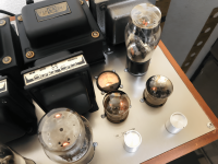
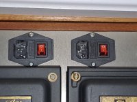
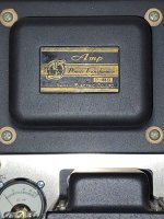
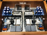
I bought a 100V DIY Japanese dual mono SET amplifier that has a couple of 717As per channel driving either a 300B, 2A3, or a 45. The amplifier has fixed bias, hum pots, and a knob to select the operating point for either a 300B, 2A3 or 45 tube. The amplifier has two IECs in the back, one for each channel and each IEC has 3 prongs.

You can see all that in the pictures attached. Unfortunately, I do not have the schematics of the amplifier.

I am going to use the amplifier in the United States. Surely, the amplifier, being made in Japan, works with 100V and either 50hz or 60hz. The power transformers are Sansui P- 44B which I believe can work either with 50hz or 60hz. So, HZ should not be an issue.

These are my questions:

1. For the voltage and ground issue, I am planning to use this step down transformer, which has 2 outlets for 100V, in 1600 Watts, which should be more than enough even with the 300Bs in place. But, I am a bit confused with the ground issue. Clearly the IECs in the amplifier have 3 prongs, and the IEC outlet in the step down transformer linked above, has also 3 prongs. So, I was planning to simply use a common USA power cord from the IEC in the amplifier to the step down transformer outlet, is that OK to safely handle the ground or am I missing something? I am not sure how the ground is handle in the amplifier, but maybe someone can understand that by looking at one of the pictures attached that shows the wiring.

2. The amplifier also has 2 hum pots. Regarding the hum pots, I was planning to do what I usually do which is: Let the amp warm up for at least 30 sec without music, turn the hum pots clockwise until I hear the hum increase. Then turn counter-clockwise until the hum decreases and then increases again to about the level
where I stopped the clockwise rotation. And then, set the pot to the middle of these two positions. Is that OK or am I missing something?

Any help is greatly welcome.

Thanks in advance!

Alan

Attachments

  • Japanese Dual Mono SET- 717A to 2A3-45-300B - 1 copy.jpg
    Japanese Dual Mono SET- 717A to 2A3-45-300B - 1 copy.jpg
    549.4 KB · Views: 199
  • Japanese Dual Mono SET- 717A to 2A3-45-300B - 7.png
    Japanese Dual Mono SET- 717A to 2A3-45-300B - 7.png
    1.2 MB · Views: 178
  • Japanese Dual Mono SET- 717A to 2A3-45-300B - 3.png
    Japanese Dual Mono SET- 717A to 2A3-45-300B - 3.png
    1.2 MB · Views: 159
  • WhatsApp Image 2024-07-26 at 10.05.54.jpeg
    WhatsApp Image 2024-07-26 at 10.05.54.jpeg
    515.9 KB · Views: 156
  • WhatsApp Image 2024-07-26 at 10.06.08.jpeg
    WhatsApp Image 2024-07-26 at 10.06.08.jpeg
    363.9 KB · Views: 169

Preamp PSU

Dear All.

I'm working around the power supply of a tube preamp i build.

I started using one transformer i had un my hands,with a 0-125 secondary...so everything was calculated considering it.
The PSU had a CLCLC filter.

So far i realized that the transformer was undersized...after some hours became very hot.

So i'm using now a 185 0 185 transformer.

To avoid to change the working point of the tubes i was obliged to add an RC cell.

What's the best configuration in your opinion?

CRC L C L C..

Or..

CLC RC LC

Many thanks in advance.

Maurizio

NAP250 clone

I'm looking at building a NAP250 clone. Since this will mostly be a nostalgia project, I'm trying to be fairly faithful to the original.

However, I won't have the volumes Naim did (for parts matching), and some parts production has since been moved to China (so I'm probably looking at greater variability to start with). The knife-edge stability of the original therefore has me a bit worried.

Here's something pretty dang faithful, but with the standard Miller compensation replaced by transitional Miller compensation (which seems appropriate as it was first proposed by Baxandall, who also has his diode in the quasi-complementary circuit):

attachment.php


It serves its primary purpose of improving the stability without sacrificing the slew rate, although I couldn't get the stability up much without introducing a lot of distortion. So the phase margin is still, well, marginal. On the other hand, the slew rate has doubled, and the frequency response has improved considerably.

Any thoughts on this, including what it might do to the sound signature?

Thanks,
Jeff.

Attachments

  • nostalgiaNAP.jpg
    nostalgiaNAP.jpg
    116.6 KB · Views: 15,970

XLR ground pin on the Neutrik NCJ6FA

1721908220785.png
1721908238054.png


I'm building a mic. preamp and will use Neutrik NCJ6FA type socket.

Pin 1 is the shield, electromagnetically it's an extension of the chassis, so this must connect to the metal chassis
Pin 2 and 3 are a balanced pair.

Any ideas what G pin signifies in the above?

I seems to align with the bottom right screw hole, so I am guess that it is helpful way being able to connect the shield of the incoming cable to the chassis at the point of entry by connecting if pin 1 and pin G on the PCB. Or alternatively, the connection between pin 1 and pin G could be controlled by a switch for a ground lift feature.

Given this is already a topic that causes a huge amount of confusion, it would have been good if Neutrik published an App. note.

1721908802809.png

Need Help for MTX TA2300

Hello,

The left channel outputs a strange sound at high volume (only when a subwoofer is connected to it, see the oscilloscope photos), like popping noises. The right side doesn't have this problem.

I tested the small transistors with a multimeter, and they seem to be functional. I replaced all 8 MOSFETs on the left side with new ones (4 were burnt out).

Thank you for helping me solve this problem.

20240801_153458.jpg
20240801_153352.jpg
20240801_153223.jpg

1w or 2.83v? Fs and response?

Trying to get my head around driver datasheets

This one lists at 2.83v
https://www.wagneronline.com.au/attachments/Audio-Speakers-PA/sbacoustics/SB34SWPL76-3-DV.pdf

This one at 1w
https://ds18.com/collections/n-12-s...ohm-dvc-quad-stacked-magnets?view=sl-76453B29

How to line the efficiency up to even power to compare?

Also Fs and response, I see some that list frequency response starts around Fs and some that are a lot lower as in the second link with 16Hz on the lower side of response and 31Hz Fs

Markaudio 11ms gen 2 water buffalo enclosure

Hello all.


I’m in the process of building the Water Buffalo enclosure for the Markaudio 11MS gen. 2.
I’ve reviewed the plans available on this site as well as those on Markaudio’s site (Identical). I have some questions regarding the plans which apparently call for doubling up the ply for a total thickness of 1-1/2 in. Is this really necessary? -seems like overkill to me as I plan on using 3/4 in. Ply with MDF core instead of traditional veneer ply core. Additionally the plan shows double thickness ply on the left side of the enclosure but not the right as seen from the front. I assume this is an oversight on the part of the person who did the CAD, or they expect us to deduce that the material is doubled on all interior surfaces (Or is this some kind of acoustic wizardry to leave one side of the enclosure at 3/4 in.?) I hate to appear daft but If I’m going to purchase $600 in ply, drivers and other materials to make this, I want to do it right. Full disclosure.. I’m trained in fine carpentry, not acoustic engineering so when I’m finished with these they’ll be of the quality that one could expect to find from a high end seller but I’ll have less control over determining the sound quality unless I get specifics in design.

Thanks in advance,
Craig
  • Like
Reactions: LeifB60

Flared BR ports with Hornresp?

Hello Hornresp modellers

When it comes to port flares, can this be modelled using HR? I have set the flare rate just for illustration purpose. In HR a segment can be set as conical, parabolic and such. Which one is most suitable for the slot port segment? Is it still conical if the port is rectangular and flare rate is like an angled board with a lip radius?

I would like to learn how to correctly enter the data for a box like this to build a Hornresp model. I think I can do the two parts of the port ok and assume the radius will be ignored by the port frequencies and just there for looks and flow. Interested in learning to correctly model such angled flare on just the exit section and both sections

Is the driver volume done as a segment too? Really struggling to understand the workflow in this situation

The illustration is similar to what I want to model acoustically. I would build such a cab with plywood outers and use CNC'ed MDF for the ports and fillets

Can Hornresp model this better, or is this best done as a BR in WinISD and somehow using the port flare function?


1719984945987.png


1719985035675.png


1719985106166.png


This will be edge treatment under assumption that these radii are invisible to the bass frequencies and for structural and aesthetic reasons

1719985672547.png

JL Audio MC-800/8v2

Hi All,

I have a JL Audio MC-800/8v2 on the bench and have a couple questions.
  1. Do we have a source for the cross over switches (SK-23D04-G 12)? I cannot find a supplier, even using Octopart.
  2. Are the power supply terminal clips available anywhere? I need one for the B+ terminal.
  3. Does anyone know what the value of the capacitors are in the RC filter on the power supply primary side? One in the amp I am repairing was corroded and the other was damaged as well. Have a 100nF fitted, but that value seems too large since the 10ohm resistors are heating up allot.
Thanks as always!
IMG_0719_H.JPGIMG_0720_H.JPGIMG_E0711.JPGIMG_E0714.JPG

Finding and fixing cabinet resonance

I have a chance to hear two versions of my speakers: real wood vs. MDF enclosures. I could detect the emphasis on male’s voice on the real wood cabinet version—there’s Umm sound along with male’s voice. So, I suspect the emphasized men’s vocal I heard was the cabinet talks.

How to find the cabinet talk frequencies?

In fact, to find it, I know there’s using accelerometer method but is there any easier method?

Also, to fix it, I think of crossover design that help fix the issue. Can I break the theory by designing the crossover in custom way, i.e., underlapping crossover points, instead of employing some sophisticated specific circuits such as notch filters?

For Sale EU- Dayton Rss265hf-4

Hi,

I don't use this Dayton audio Rss265hf-4 for a while so I sell it.
In good condition.
Buy in 2021 and use in apartment.

Ship in Europe
Price 125€ SOLD
+ shipping and PayPal fee

Attachments

  • IMG_20240715_161023.jpg
    IMG_20240715_161023.jpg
    182.5 KB · Views: 55
  • IMG_20240715_161035.jpg
    IMG_20240715_161035.jpg
    188.2 KB · Views: 55
  • IMG_20240715_161041.jpg
    IMG_20240715_161041.jpg
    181.5 KB · Views: 60
  • IMG_20240715_160937_edit_640347667890830.jpg
    IMG_20240715_160937_edit_640347667890830.jpg
    403 KB · Views: 48

Totem Model One potential cabinet repair

I have a pair of Totem Model One which was made in the 90 as far as I can tell. The cabinet is in bad condition. I was trying to sell it through usaudiomart.com at https://www.usaudiomart.com/details/650099021-totem-model-one-bookshelf-speaker/

However, when the buyer received it, he claimed that one of the woofer was making cracking sound. It was working perfectly fine before I shipped it. Anyway, I offered the buyer to ship it back to me for refund. Once I received the speaker, I found that when I shake both speaker, I can heard something inside is moving. I therefore concluded that the crossover was loose and not mount firmly onto the speaker cabinet. And during shipping, the connection got loose. When I tested the speaker, I found one woofer has cracking sound and then maybe half minutes later, it has completely no sound.

Anyway, since I am not able to sell it. I am thinking of fixing the cabinet. Is there any good options for fixing it? I have disassembled everything already.

If I remove the veneer and do wood paint and oil it like some other Totem speaker such as in Mahogany. How is that procedure work.

By the way, the internal wire are just so thin. My cheap RCA cable is even thicker. Also, this is the first time I see the so called specially modified SEAS tweeter.
Anyone know what is the small capacitors on top of the big capacitor for? They are only 0.1uf.

Attachments

  • IMG_2698.jpg
    IMG_2698.jpg
    346.6 KB · Views: 89
  • IMG_2697.jpg
    IMG_2697.jpg
    448.1 KB · Views: 86
  • IMG_2696.jpg
    IMG_2696.jpg
    567.8 KB · Views: 81
  • IMG_2695.jpg
    IMG_2695.jpg
    597.7 KB · Views: 89
  • IMG_2694.jpg
    IMG_2694.jpg
    412.7 KB · Views: 91
  • IMG_2693.jpg
    IMG_2693.jpg
    585.7 KB · Views: 93
  • IMG_2688.jpg
    IMG_2688.jpg
    313.6 KB · Views: 95

For Sale New Altec 604 8H-III Speakers & N604-8C Crossovers

Continuing to purge my inventory as I physically diminish.
Speakers and crossovers are new and have never been removed from the factory packaging.
Great Plains Acoustics, the recent successor to Great Plains Audio (successor to the Altec Lansing Corp.), has a this package on sale from $4,078 to $3,465. It is out of stock.
$3000 plus shipping.

M

Active 3/4 way HiFi

Hello all, I am new to this form and DIY audio in general although I have long had a passion for audio. I currently own a pair of revel M106 and my father owns some Salon 2s. I am interested in making the "Best" Horn loaded "party" speaker. I am a big fan of music festivals and want to recreate that chest thumping bass and levels where I need to put my musicians earplugs in but as high fidelity as possible. I have been taking some inspiration from the likes such as funktion-one, hennessey sound https://www.hennesseysounddesign.com/point-source/ , and KV2 VHD2 https://www.kv2audio.com/products/vhd-series/vhd20.html . This sound system will eventually be placed in a "great room" likely a flown array to get even front to back coverage. I am currently thinking of 4" 1.4" exit beryllium compression tweeter such as https://radianaudio.com/collections...s/951-4-diaphragm-1-4-exit-compression-driver and possibly paired with one of these horns https://www.parts-express.com/B-C-M...ctivity-Horn-70x55-4-Bolt-294-6184?quantity=1 . Hennessey makes mid bass and subwoofer boxes that do 75-300 and 25-100hz respectively that I would like to emulate or possibly just purchase.

My biggest question still is how to complete the midrange likely 275/300-1???hz I want to have as high fidelity as possible but it also needs to be comfortable at 120 and reach up into that 130+db peak levels.
maybe https://www.madisoundspeakerstore.c...nx-003-e0073-08-6-graphene-cone-woofer-8-ohm/
or Purifi Ushindi 6.5" PTT6.5M08-NAA-08

I plan to do this all on active dsp crossovers with 7 separate amplifiers to get the timing, crossovers, and frequency response perfect.

Any and all advise is welcome!

Preventing resonances, should I add foam or something?

Hi

Further to my previous thread, this sub design has been cut and partially glued. It's a Focal 8 inch flax cone 4 ohm driver, tuned to around 30Hz. I've added an extra panel to the front to double up thickness and recess the driver. It will sit behind a wine rack in my kitchen music system. WinIsd models it flat to 30Hz at 105dB/1m. I've bought a mini Dayton LF dsp to provide a steep high pass filter below tuning as the enclosure is twice the Focal recommended size at around 1.5 cubic feet including port space. If anyone has a cheaper or better value idea for a high pass DSP, I'll be interested in that too as I'll be able to return it easily via Amazon.

https://subbox.pro/en/b/Dma3w9kjt

I will put it all together tomorrow, and just wondered if anyone had any advice, or comments.

Specifically, regarding resonances, should I add some foam or material to soak up any higher frequencies, e.g. on the inside left panel? Or is that just a waste of time and space?
Also if someone can point me to a guide on how to crimp the speaker terminals on the inside that would be very helpful.

Thanks.
PS. Here is the thread re the room if you're interested. https://www.diyaudio.com/community/threads/new-kitchen-setup.415463/

Diesis Mini Bookshelf 1979 refurb

Hello Chaps, been a while since I was on here and even had to reregister as my email has changed.
I just recently pulled my old Diesis MinI bookshelf speakers from the loft. I bought them new in 1979. They were made by Brian O’Rourke and marketed as Diesis. Brian went on to create Ruark Speakers with his son Alan. They are only down the road from me too. These speakers were very solid and fitted with SEAS tweeter and Woofer/mid, and a SEAS supplied crossover. i bought them after a blind test in the shop and they mistakenly played some Spendors and I went Oh yes. They said oops mistake as they are well put of your price , but these Diesis have a similar sound signature and he was right, they cost a bit more than my limit… But they are very smooth but with no colouration.
Ive been through some Dutton 33’s and 332‘s and more recently Rega RS5s but the little Diesis kept calling, especially as they are small enough for the missus to accept in the lounge.
Anyway, back to the present day:
Hooked them up and realized one speaker was quieter than the other. So did the usual and ascertained its the speaker not amp or anything else. Took them apart and saw to my dismay that the 2 woofers are covered in oxidation so that needs doing. Then noticed that the crossover looked a bit cooked on the one that was quieter. So I set out to try to ascertain all the values. Not so easy , so I hooked out the other crossover only to find it has different make caps etc. A bit odd as I bought them new so no one has fiddled with them.
So, I’m struggling to see what size the Inductors are. I can read the Caps on one crossover ok so that good. Also the resistors on that board , not so easy on the other board. Both the air cooled Inductors look ok and I’m to understand they rarely have a problem.
So here is the information I can see. Hoping someone on here can work out what I need to buy …

Crossover 1 :Has a sticker which reads : D 093 P 8ohm, 2-way 3120176, fc: 2000Hz.
Inductor; 6F8 5%
Caps 1; CEO 2SP 50V 12mF (K) The m is actually the symbol for micro but can’t find it on my keyboard.
Caps 2; CEO 2SP 50V 8mF (K)
Resistors 1; RGB5 10 Ohms J Noble62
Resistors 2; 5W 7 Ohms J Micron86
Crossover 2:
Inductor; can’t read at all
Caps 1 ; 12mF 50V
Caps 2 ; Can’t read till I remove it.
Resistors 1; D(ohms symbol) C. 811 4R7 5% 5W
Resistors 2; can’t read at all.

I will upload a photo of the crossovers. I have more photos if anyone needs extra.

Appreciate any help to get these up and running as to be honest id forgotten how nice they sound, even with one speaker a bit quieter… ( I have Attacama Stands for them.)

I know these are not or even were not state of the art speakers but do you guys think standard Alcap Caps and equivalent Resistors and inductors will be ok or should I go a bit more upmarket? I will likely use Falcon Accoustics or Wilmslow Audio as im in the UK.

Thank you guys, appreciate any help at all.

Cheers
Phil
IMG_5242.jpeg
IMG_5239.jpeg
IMG_5237.jpeg
IMG_5244.jpeg

Help with a 6L6 PP design

I still consider myself a newbie. I have put together a couple of amps, mostly monkey see monkey do. (no offense intended to the primates) I have put it together from scrap, used parts, and junk box parts. A PP 6L6 amp using a floating paraphase phase splitter, a 6SN7. Schematic attached. I'm a bit surprised that it starts to clip at just about 18 watts rms. I'm testing at 1 kHz, and yes, the output transformer was recovered from a 1940 RCA Victor floor standing phonograph/radio. But a "high end" one that had a PP 6F6 fixed bias amp, that claimed 19 watt. Any suggestions as to what I might have gotten wrong would be appreciated.

Amp is working sorta OK, especially given the low quality OPT. I am attaching a second image, which is a screen capture of my scope. Reminds me of when Polaroid Corp sold instant cameras specifically for Tek scopes. (Now you know how old I am). There are 3 scope traces: Blue and yellow are the output tube plates, violet is the output into an 8 ohm resistor load. I have fixed the imbalance in the magnitude of the two tubes, but I have not figured out what might be causing the "step" in the output waveforms, seen near the peak of the sin wave. Anyone seen anything like this before? Thx.

Attachments

  • Corrected 6L6 PP amp.png
    Corrected 6L6 PP amp.png
    12.2 KB · Views: 270
  • IMG_7938.JPG
    IMG_7938.JPG
    526.1 KB · Views: 212

A new pair of peachy-keen tweeter hookup wires, being sold at a loss.

Up for grabs is a pair of Cardas Litz Wire twisted-pair 15-ga. internal hookup wires, 9 inches long each.

IMG_0942.JPG


Factory-terminated with silver solder. (Note, you can't just cut and strip Litz wire; you have to burn off the varnish that makes it Litz wire.)

There was a miscommunication re: quantity, and I ended up with an extra pair of twisted pairs. They cost me about $65 all told, but I can let them go for $25, with free shipping to US destinations.

PayPal payment, please.

john

Which type are Erie metallised cap for crossover Ditton 25

I have a question about a vintage speaker's crossover. I would like to recap the crossover of my Celestion Ditton 25. I would like to know if wise and with caps to choose from.

The crossover has 4 inductors and 4 groups of capacitors.

-First, a black Elap 50v 25uf, and

-three, with the same shap, red ''Erie'' metalised 150v 2uf A308, ''Erie'' ''metalised'' 150v 3.5uf A316 and ''Erie'' ''metalised'' 150v A316 3uf.

So there is one for each of the 4 drivers, the two turbine type tweeters have different one.

For the Elcap, it seems clear that is an electrolytic cap, but for the second it is less clear,

I gave a look online and the metallised cap is described as a fast cap. There seems not easy to find 150v electrolytic cap. So it is not an electrolytic cap, which is its type? Film?

The second mystery why there are two different model numbers.


A mate told me that the film cap could give a strident high. I listen to classical and early music so I won't experiment in this field.


In the past, I recapped my Leak 2060 with 3 blue electrolytic cap 50v brought from Falcon Acoustic in England. It was simple, I got ones with the same spec. It was a huge improvement.

For Sale Loudspeaker drivers and horns

After several decades of speaker building, I’m liquidating some of my inventory of speaker drivers, horns, and miscellaneous components. To wit:

(2) Faital 12FH520 12” neo woofers, used in excellent condition - $400

(2) Fane Sovereign Pro 8-225 woofers, NIB - $100

(2) Faital HF10AK compression drivers, used good condition - $300

(2) Dayton D250P-8 comp drivers, excellent - $100

(2) PRV D250Ph-S comp drivers, unused - $50

(2) Auto-Tech E-JMLC600 elliptical horns with 1” throat, used/excellent - $600

(2) Faital LTH142 1.4” horns unused - $150

As stated, all are in good-to-unused condition. All prices are for the pair, shipping not included, and everything is negotiable. I’d prefer CONUS only, but will consider international, and welcome local pickup. I’m in Tewksbury, just north of Boston. Payment accepted: Paypal F&F, Venmo, Zelle, Postal Money Order and cash.

Teflon Coupling Capacitors 0.1 0.2uF for tube Amps

Hi, I am looking to start a new thread, on 0.1 uf and 0.22 uf Teflon Coupling Capacitors and any other 0.1-0.2uf suggestions for tube amplifiers under $60 USD each

The Russian FT1 FT3 K72 and now Solen SQ3 series all fit this category.
I am sure their are others and wonder what results people have had with these .
Their are Blogs comparing the FT1 FT3 and K72 to Vcaps but wonder how others have found them in coupling positions between say a driver tube and out put tube ie 6SN7 > 2A3 /300 single ended , or E280F > 2A3 /300B , Ra, CCS or Choke loaded

Max performance lag compensated amp

I've been enjoying the modified Parasound HCA-800 mkII. It's a simple lag-compensated amplifier, with a lead-lag network at the IPS to add some 2nd order loopgain roll off. No fancy modern TPC or TMC, just a classic topology that dates back to the JBL SA-600. It sounds live, with solid bass, it's a super detailed yet easy listener.

So what's the best we can do with lag compensation?

Here's an evolution of it with generous stability margins, and distortion products around -125dB, and that's with TO-3 outputs! Haven't built it yet but this might be the next project to be put to board.

Attachments

  • lag_stab.png
    lag_stab.png
    32.7 KB · Views: 342
  • lag_imd.png
    lag_imd.png
    23.5 KB · Views: 345
  • lag_schem.png
    lag_schem.png
    47.2 KB · Views: 355

Purpose of Focus Offset trimpot on CDM-1

Just out of curiosity: what is the purpose of the variable resistor 3132 (FOCUS OFFSET, 47k) on the Philips C.D.M-1 mechanism? Neither the service manual of the mechanism, nor the service manual of the CD player (Marantz CD-94 in my case) does mention anything about this adjustment.
The only focus related adjustment is just setting the height of the turntable with a Torxx screw until the voltage on the focus motor is 0V +/-100mV.
This variable resistor apparently balances the input offset of the Focus Error amplifier uA741. Would it make sense to disconnect the flex cable from the photodiodes going to the NE5514 preamplifier, adjust 0V on the output of the uA741, reconnect the photodiodes, and then do the turntable height adjustment? In other words, do electrical offset zeroing first (open loop) and then do the mechanical zeroing (closed loop).
  • Like
Reactions: weissi

How small box can an Faital Pro 18XL1600 work good in?

Have 4 big Faithal 18XL1600 that I buy 5 years ago that i never uses,
They was/are mounted in 4 big PA-boxes, but im thinking if I can build some "nicer" cabinettes for them and also a "potent" MTM or a MM/TM.

Maby use two 18XL1600 per side?
They are 8 ohm drivers!

My biggest "worry" is that I think they will need BIG boxes to "work good".
So I ask you guy´s, how many liters does it need "as a minimum", to play desent?

regards John

Attachments

Second opinions needed on a system design

I have restaurant and we need to replace our sound system with a new one that can produce clear sound with ample headroom in case we need to play things loud (which we do occasionally). Over the last two weeks, I worked with our DJ and one of our in-house technicians to design a replacement system and I'd like to get much needed second opinions from you guys on what you think of our plan. Harsh criticism is welcome whenever warranted. Below are the details and in the bottom you should see the layout of our venue.
  1. Budget: $20,000 with all the equipment will be purchased from the US. We still need to pay for shipping, customs, and installation which'll be another $20k.
  2. Venue Design:We have three areas. A restaurant, a sushi bar, and a lounge. The restaurant is the biggest in size and music start to get loud at 11p until we close at 3a. The sushi bar has a couple big tables and a bar seating area where we keep the music volume on the low end just as background. The lounge seats around 30 people and we play background music a little louder than the sushi bar area but not close to the restaurant area.
    1. The restaurant: We have a seating capacity of 150 guests plus the floor staff (around 40 on average). The area is oddly shaped with the following dimensions: Length: 21.5m in the shorter lower edge and 23.1m in the upper longer edge. Width: 14.8m, and ceiling height: 6m. There are two beams in the middle area which we can use to mount speakers. Other than that, we only have the upper wall and the walls on the right and bottom sides of the restaurant. The wall on the left side is a floor-to-ceiling glass wall except for the three beams shown in dark grey in the layout. The DJ booth is almost centered horizontally (shown in the upper side of the restaurant area in the layout).
    2. The sushi bar: The dimensions of this area are: Length: 10m, width: 8.4m, and the ceiling height is 6m. It is open to the entrance area and the entrance area is visually blocked from the sushi bar area by some artificial greeneries.
    3. The lounge: The dimensions of this area are: Length: 14.5m, width: 7.7m and the ceiling is 3.75m. It's open to the sushi bar area and visually blocked from the sushi bar area by decorative greeneries as well. So there is no hard barriers of any kind.
  3. The plan: Our thinking was that we have to incorporate pendant speakers that have a wide enough dispersion angle as the backbone of our system, supplemented by wall-mounted speakers to provide a fuller sound coverage without being overpowering. So here it goes:
    1. The restaurant: In the restaurant area, our plan is as follows:
      1. eight JBL Control 68HP pendant speakers (passive) in a two-row configuration with 4 speakers mounted along each of the two longer sides with the two on the edges of each row being 2.5m away from the two side walls, and the remaining two are placed 5.5m away from each other in this rough placement for one row example: 2.5m X 5.5m X 5.5m X 5.5m X 2.5m (the X represents the speaker). The two rows will be about 5m from each other. We plan to place them 1.5m from the ceiling (4.5m from the floor).
      2. two JBL Professional Control 28-1L speakers (active) mounted on the wall behind the DJ booth to its left and right sides angled downward. These two are meant to provide enough sound to the area in front of the DJ booth which is usually preferred by customers who love loud music.
      3. ten JBL SLP14/T wall mounted speakers distributed across the restaurant area to provide just enough sound for a fuller experience without being overly powerful. The basic thinking behind it is a budget-friendly option that can eliminate dead spots without being too powerful.
      4. two JBL Professional PRX918XLF subwoofers (active) which will be placed on the floor in front of the DJ booth slightly angled toward the sides of the restaurant.
    2. The sushi bar: In this area, our plan is as follows:
      1. one JBL Control 68HP mounted in the ceiling at 4.5m from the floor between the two tables (the tables placement in the layout is not accurate. They are closer to each other). It should provide enough background music to the two tables and the bar seating area.
      2. two JBL SLP14/T wall mounted speakers on the wall of the bar facing the bar seating area and two tables.
    3. The lounge: In this area, our plan is as follows:
      1. six JBL Control 68HP pendant speakers placed in a two-row configuration with the first one being 2.5m away from the two side walls (left & right) and 3.9m away from each other. The two rows will be about 2.9m away from each other. They'll be 3.75m from the floor (the actual floor height is 6m but there's a secondary decorative steel ceiling at 3.75m from the floor which has many openings where we can drop the speakers through these openings).
      2. two JBL Control 60PS/T subwoofers (passive) which will be centered vertically and horizontally will be evenly placed across the seating area.
    4. Amplifiers: As per our calculation, we need 5,350w of power to power our 27 passive speakers and 2 passive subs. We looked at Crown (XLi, XLs, CDi), QSC GX7, and Behringer NX4-6000. We ran different budget and performance simulation scenarios. I immediately excluded the Behringer fearing its reliability (or lack thereof). The Crown XLs was slightly out of budget but can be manageable. The Crown CDi was way out of budget. The QSC was similar to the XLs in terms of budget. However, what we couldn't figure out is what we'd be gaining and losing in terms of performance under each scenario. Here is what we came up with which'll provide us with 5,800w of power:
      1. two Crown XLi3500 Amplifiers
      2. two Crown XLi2500 Amplifiers
      3. one Crown XLi800 Amplifier
    5. Processors and other equipment: Currently, we have one dbx Venue 360 processor. In our calculation, we will need another dbx Venue 360 and an ART S8 Signal Splitter to be able to process the sound as per our needs. The farthest speaker from the rack is ~37m. We will use 12 AWG cables throughout. Please check the layout for the location of the equipment rack (red rectangle to right).
This configuration will cost us $16,000 (without shipping, customs, and installation), so it's within our budget.

What have we missed? What other alternatives should we consider?

Source Options for TV & Music into Hypex Amps

Hi all,

Really wasn't sure what to call the topic or the correct place to put it so hopefully this is ok.

I'm looking to setup a room for mainly listening to music, but tv will occasionally be played also.
My current gear will be a new set of speakers i have just finished, 3 way active with Hypex amps.

My main questions relates to how I ideally get my audio sources to the speakers.
Eg. I was originally going to put these speakers in a different room and use the preouts of my Denon X3800h, but i've changed that plan and
only have an older AVR in this room with no preouts.

Ideally I'd like a digital source to feed the hypex amps for music. I don't mind how i get the tv audio to the speakers.
The main thing i want is a volume control so i dont have to modify volume on the hypex amps.

I really havent had much to do with amps/media streamers etc, aside from AVRs, so if you can point me in the right direction here it would be much appreciated.

Hopefully this isn't too vague. Thanks in advance!

Break In

The role of dominant poles and component quality in high-power electronics and audio systems is crucial. Defective or substandard semiconductors can act as unintended oscillators, generating structural noise and high sound pressure levels (SPL) with minimal energy input. This chapter explores the historical context, the evolution of semiconductor technology, the concept of break-in, and strategies to manage dominant poles and improve component quality.

In the early days, solid-state amplifiers and Class D amplifiers faced significant challenges due to low-grade semiconductors. These components often exhibited high noise levels, distortion, and reliability issues, which affected the overall performance of audio systems. Vacuum tube technology, with its linear amplification characteristics and higher tolerance to imperfections, initially maintained a competitive edge.

Early semiconductors had inconsistent material quality and manufacturing defects, leading to unpredictable performance and higher noise levels. Circuit designs did not fully leverage the potential of solid-state devices, resulting in suboptimal performance. The limitations of early semiconductors exacerbated switching noise and "Class D glare" in amplifiers. Ineffective filtering techniques further increased these issues, making it challenging to achieve clean audio output.

Advancements in semiconductor manufacturing and design have addressed many of these early challenges. Today, high-quality semiconductors are characterized by superior material properties, precise manufacturing, and optimized performance. Modern semiconductors are produced with high material consistency and manufacturing precision, reducing noise and enhancing performance. Circuit designs now fully exploit the strengths of semiconductors, incorporating advanced feedback control, better thermal management, and optimized signal paths.

High-quality low-pass filters and other advanced filtering techniques effectively suppress high-frequency switching noise in Class D amplifiers and digital power supplies. The use of inductors and capacitors with appropriate values and high-quality materials ensures effective noise reduction. Digital signal processing (DSP) techniques manage noise and improve signal integrity in digital power supplies and Class D amplifiers. Real-time correction and enhancements through DSP help mitigate imperfections and enhance audio quality.

Break-in refers to the period during which electronic components stabilize after initial use, affecting their performance. Both semiconductors and capacitors benefit from a break-in period, which can lead to improved performance over time. Semiconductors may exhibit changes in their electrical characteristics during initial use, leading to performance improvements as they stabilize. Long-term changes due to heat and electrical stress can further enhance performance. Electrolytic capacitors benefit from a break-in period during which the dielectric material stabilizes, improving performance. Film and ceramic capacitors can also experience improvements with brief electrical conditioning.

Dominant poles are frequencies where minimal energy input can significantly excite a device, leading to potential performance issues. These poles are critical in both semiconductor and speaker systems. The resonance frequency (Fs) of a speaker is a dominant pole where the speaker cone naturally vibrates with minimal energy input, potentially causing unwanted resonances and distortions. Management strategies include using damping materials, notch filters, and structural reinforcement to mitigate the effects of Fs. For semiconductors, the transition frequency (ft) is a dominant pole where the gain starts to decrease significantly, potentially causing instability and oscillations. Operating below the dominant pole, using high ft design, and effective filtering can help manage the effects of ft.

Defective or substandard semiconductors can act like unintended oscillators, generating structural noise and high SPL with minimal energy input. This is due to the crystal-like structural oscillation inherent in low-quality semiconductors. Defective semiconductors can resonate at their dominant pole with very little energy input, similar to how a crystal oscillator works. This efficient energy conversion leads to significant excitation with minimal power. When excited at their dominant pole, these semiconductors can produce high SPL, creating structural noise that is perceptible and often uncomfortable to the human ear.

High-end manufacturers implement stringent quality control measures to ensure component reliability and performance. Grading components based on performance metrics and structural noise is crucial for maintaining product quality. Components are subjected to current passing tests to measure structural noise and performance, and are then graded from Grade 1 (highest performance) to Grade N. Only Grade 1 components are used in premium products to ensure the best performance. For high-end products, replacement parts should be sourced directly from the manufacturer or the product should be returned for factory servicing. DIY repairs or local servicing with ungraded components can degrade performance and lead to dissatisfaction. Directly contacting semiconductor and capacitor manufacturers to request high-grade components ensures stringent quality standards. Purchasing components in bulk from reputable suppliers like DigiKey or Mouser and grading them yourself is an option for ensuring quality, though it requires specialized equipment and expertise.

Dominant poles and component quality are critical factors influencing the performance and reliability of high-power electronics and audio systems. Early challenges with low-grade semiconductors underscored the need for high-quality materials, precise manufacturing, and advanced design techniques. Modern advancements, combined with rigorous quality control and grading, enable the creation of high-performance, reliable electronic products. Understanding and managing dominant poles, structural noise, and the break-in process are essential for professionals striving to achieve optimal performance in their designs.

This chapter provides a comprehensive overview of the critical factors influencing the performance and reliability of high-power semiconductor applications. By incorporating proven facts and modern practices, it serves as a valuable resource for professionals in the electronics industry.
Acoustic 450 Repair

Hi, I'm trying to repair an old Acoustic 450 amplifier.
I got it after someone plugged the amplifier to 230V mains with the power transformer was set to 115V and someone in the past bypassed the 7A fuse so many components went faulty. The bridge rectifier and the main filter caps was faulty as well as the original drivers and two original output caps. I replaced all the output transistors with 2N3773G and the drivers with 2N5320 and 2N5322 as well as all the electrolytic caps and diodes on the power amp circuit.
With a variac supplying a low operating voltage and a bulb limiter with the output transistors and a 8 Ohms speaker load connected both drivers are getting extremely hot and after 20 seconds or so both getting burnt.
I've already tested all the small transistors out of circuit with a Chinese LCR TC1 and all tested well.
As far as the PSU, the bridge rectifier and the main filter caps were faulty and were replaced with new ones.
With new drivers and with a 100ACV from the variac (power transformer wired for 230V) and without the power transistors the DC voltage at the speaker output is varying from 7.5V on startup to 5V after 1 minute.
How can I make this amplifier to work without blowing the driver transistors?

Attachments

eBay mono LM1875 kit

(Mod note... thread split from here:
Beginner's Gainclone, HiFi LM1875, The Amplifier Board)

-----------------------------------------------------------------------------------------------

Hmmm Been looking at this as well.
Couple of points;
I located the 'Original'.. and quite good actually..design (haodiy.net) of the currently widely available on ebay, as the 'cloned' 2$ lm1875 'kit'.
PCB layouts..Amp and PS are downloadable at haodiy.net..for DIY PCBs.

Ebay Vultures have shrunken the pcb tho (cheaper to make).. but it's still a good usable layout .. absolutely so for the price 😉
Their Odd low quality parts / value substitutions are definitely for the trash bin though. Just use the pcb.

Daniels' final circuit, seems as oddly complex.. IMO .. with 24 parts.
Certainly seems so as compared to the often described as 'excellent' ESP layout which uses Far fewer parts (15).
Note though that Both the Hao design author And Rod Elliot (esp)both state that the 1875 approaches High end audioweenie sound.. but does not quite achieve it.. all claims aside

Your choice... Suggest trying either the Haodiy OR the ESP circuit as experiment, then comparte Could be interesting and worth reporting back on it?

Tuning / Tweaking of BP 115 A

Hello,

I bought some nice two way Bluetooth loudspeaker with accumulator (battery).
Its a Thomann cheapo named Fun Generation BP115A with 15 inch bass and big tweeter. It has 93db efficiency (I found the repair driver PDF spec), stiff paper bass diaphragm and I guess - as far as I could see - a tweeter with a decent sounding mylar diaphragm. Only the tweeter seems to have a 12 db filter with 4 Ohm resistor. Bass seems to be directly driven by the amp.

In original condition it sounds as most PA loudspeakers o.k.. But in my ears - like in most PA systems - some typical hifi faults are built in. In order to bring efficiency up with a trade off in sound quality.

It is easy to open the plastic loudspeaker enclosure. The box is pretty undamped (only just a little little bit black BAF wadding and a highly tuned bass reflex. I want to turn this speaker in a good sounding hifi speaker capable of deeper bass than the 60 Hertz lower cut off frequency.

So tuning - tweaking of the FunGeneration BP 115 A loudspeaker was done:

1. putting some damping on all surfaces and fixing it
2. a method I prefer to get good sound is covering the bass diaphragm on the front side with aluminium foil.
3. Tuning the bass reflex to 30 Hertz as I want to hear the lowest octave - even if it is surely sloping.


You can see some fotos of the loudspeaker which are self explaining.
The aluminium foil is just simple foil used in the household. Glue is simple glue which fits for paper and metals.
You cut the foil into pieces (form of cake pieces) put thinly the glue on the backside of the foil an then fix it with the use of your fingers to the diaphragm beginning from the outer edge. I am used to do this since the year 2000. I had for ten years a website online exactly describing how this is done with thinner foil from the gold smith but it seems to be too much work for the most Do it yourselfers to try this tweak out. As I (nearly) never found anyone reproducing this method.

From theory it is known that the combination of metals and paper can bring a lot more stiffness to the diaphragm (known since the 60ies, but history of loudspeaker building describes this in patents since the 30ies of the last century - it means right from the beginning of loudspeaker production of the dynamic type). For germany it was Dr. Emil Podzus (aluminium foil and hard foam), later it was english speaking D.A. Barlow in the 60ies with duraluminium sheets and expanded polystyrene of thick quality. In germany these aluminium foiled loudspeakers are known as Podzus-Görlich loudspeaker drivers. Mr. Görlich was helping out as a young man at the factory of Mr. Podzus. He later produced these diaphragms with aluminium foil and hard foam. He does it until today.

I measured the loudspeaker diaphragms paper + aluminium very often. One sided and both sided (last means it is a sandwich-cone). Coating of the driver on just one side brings resonances down - makes the speaker sometimes more linear - but always the loudspeaker driver becomes much more stiff and has therefore a significant better impulse reproduction.

Best is this checked by ear while covering one driver with aluminium foil and leaving the second stereo speaker undoped. You can then use your balance knob on your amplifier for an A / B listening test.


Here about the theory:

D.A. Barlow: The Development of a Sandwich-Construction Loudspeaker System. Page 159-171. From the AES anthology of articles on loudspeakers, article written 1970.

Citation begin (page 160):
"As paper cones are thin, these resonances are bending modes. The stiffness of a material in bending, for any given geometry and edge condition, is proportional to Young`s modulus and the cube of the thickness, ignoring variations in Poisson`s ratio. ... On this basis, paper is much stiffer than metals (except beryllium) in spite of its much lower modulus, and lower density materials such as expanded plastics are even stiffer, as may be seen in Table. A method of obtaining still greater stiffness is sandwich construction. ... In bending, the maximum stress and strain occur at the outer fibers, the material at the neutral axis being unstressed. Better use of material can thus be made by concentrating it at the outer fibers. A familiar example is the tube. In the case of large areas, the same effect is obtained by using a thin high-modulus material for the outer surfaces, and a light-weight material or form of construction for the core. ... This sandwich will of course be much stiffer than the same total weight of either material used separately. The skin material should have the maximum ratio of modulus/density. Beryllium, the best material, is impractical due to difficulty of rolling and possible toxicity, so aluminium is the obvious choice. The core should be as stiff as possible in the thickness direction and have minimum density. Honeycomb aluminium or impregnated paper are frequently used in aircraft construction and could be used for flat diaphragms."
Citation end.


The Thomann bp115 a becomes after this tuning much more listenable and precise. I use it with the loudspeaker put on the side as the tweeter and the bass seem to be better time aligned than with the tweeter upside. (Listening position loudspeaker on the floor and listener standig upright).

The mylar tweeter sounds quite good, I like it.

Dragan from Germany

Attachments

  • IMG_20210806_115859.jpg
    IMG_20210806_115859.jpg
    388.2 KB · Views: 552
  • IMG_20210806_172715.jpg
    IMG_20210806_172715.jpg
    589.3 KB · Views: 547
  • IMG_20210806_120233.jpg
    IMG_20210806_120233.jpg
    420.8 KB · Views: 545
  • IMG_20210806_120244.jpg
    IMG_20210806_120244.jpg
    506.2 KB · Views: 521
  • IMG_20210806_120321.jpg
    IMG_20210806_120321.jpg
    360.4 KB · Views: 533
  • IMG_20210806_120525.jpg
    IMG_20210806_120525.jpg
    516.2 KB · Views: 400
  • IMG_20210806_121805.jpg
    IMG_20210806_121805.jpg
    457.2 KB · Views: 387
  • IMG_20210806_123022.jpg
    IMG_20210806_123022.jpg
    562 KB · Views: 366
  • IMG_20210806_132448.jpg
    IMG_20210806_132448.jpg
    412.8 KB · Views: 404
  • IMG_20210806_133042.jpg
    IMG_20210806_133042.jpg
    664.9 KB · Views: 412

Redo?

I've had a 70s Pioneer PL 560 for several years, and after making crackling noises at start up and finish for the past 4 years or more, the left channel needs a recap I think, as it's quit completely.
My favourite turntable is an Acoustic Research AR XA, and if I need a shop to do a recap anyways, I'm wondering if anyone has made this into a stripped down fully manual turntable.

My AR XA is comparatively shocking underneath- electronic parts wise, apart from the motor, it looks like it has a run motor cap, and a thump suppressor cap at the motor switch. That's it.
The AR has gotten me used to a fully manual turntable.
I love the Pioneer tonearm compatability with so many of my cartridges, easy availability and affordability of extra headshells, and stylus profiles I've already collected.
Has anyone modified one to have the simplicity of an AR XA? One thing I'm considering is rca socket output, to facilitate using leads I already have of several differing capacitances.

High SPL 3 Way

This is what I have came up with so far:

Schiit Bifrost DAC > MiniDsp DDRC-88A > DIY Hypex Ncore based amplification > active 2/3 way.

I want to use the Beyma CD10ND or their neo 1.4” for my HF, paired with an SEOS 12/15 I've done countless hours of research on them, and they appear to be exactly what I'm after. At 111db/w and 70w RMS they should be able to hit 129db. Their minimum crossover is 1,200hz, but I’d like to cross them around 2,000hz if I use a mid.

I haven’t modeled anything, or done a lot of research on my mid at this point. I know that I will definitely have to horn load it to get close to the output of the CD and woofer without multiple mids. I’d like to avoid multiple mids to avoid comb filtering if possible. Horns seem extremely hard to find for a 6-8” midrange. I’m open to all suggestions for a mid/horn combo that’ll reach into the 125+ spl area with pretty low distortion.

For my woofer, I'd like to go with the Beyma 15P80ND, or Faital Pro 15FX600. I've dome some modeling on both, and while I'm no wizard on WinISD yet, they appear to model very nicely. With the efficiency and power handling of both options, it should be able to match output nicely with the CD. I'll be measuring with a Umik and adjusting levels accordingly once built.


The LF will be handled with several high efficiency 18's or 21's on Inuke power (preferably two 28hz tuned Devs loaded with San21's on an NX6,000), and 2-4 cheaper pro 18's on a NX3,000/6,000 to even out the nulls but I'm still working on that aspect as well. Whatever combination I go with will be crossed anywhere from 120hz-80hz to them.

With the 4 presets, I'll make one outdoor event setup, use 2 others for the 2 main venues and leave one open for special shows. The largest venue they will play in is 5,000sq/ft and the largest outdoor gathering they'll provide sound for is 250 or so people.


Let me know what you all think! Again, I’m open to any and all suggestions. This is just what I have came up with so far. Thanks for any input, or experiences. I appreciate it all!
  • Like
Reactions: DblAA

Unbalanced source > balanced load and vice-verse

In 2010 or 11 Bruno Putzeys posted how proud he was of the quality of the differential input on his NC400 amp. Bruno sternly cautioned builders to never install an RCA input for unbalanced sources, instead preferring:
Unbalanced source RCA output > RCA to XLR adapter at the source > balanced IC > NC400 XLR input. He said such application approached the performance of a balanced source.

I "tried it both ways" as Deputy Barney Fife would say and IMO Bruno gave good advice (shocked, not.)

If using a simple XLR to RCA adapter, is this the best method to connect a balanced source > unbalanced load?

Balanced source XLR output > balanced XLR IC > XLR to RCA adapter at the load > unbalanced load. Does this approach the performance of a balanced load?

Dayton-Wright ESL

I just acquired a pair of DW ES speakers w/o any ID on them as to model. I am a total rookie when it comes to the ES world. They have 10 panels and 2 tweeters. The bias supply is an ST-300A. I’m reasonably sure there is no gas left in the bag. The person I got these from tried to power them up. One side crackled and the other was dead. The story I got was they were in a damp basement for decades. I took the grills off due to mold and wiped down cabinets. It looks like one speaker has a corroded connector in need of replacement. Any info on these dudes would be helpful. Did some on-line info gathering but haven’t found any links to manual or model #
Dan

Preamp recommendations

Hi guys..at present I am using a DEQX HDP Express ii preamp/DSP controller/crossover/etc to feed XLR output from an Ian Canada DAC stack to DIY KT120 tube monoblocks which drive DIY open baffle mains. The DEQX unit also has 2 subwoofer outputs, both connected to active subs with line-level and LFE inputs only.
I would like to build a preamp to replace the DEQX unit - I would lose the DSP speaker and room correction capabilities of the DEQX, but I have a MiniDSP 2x4HD which I could use for subwoofer crossover/alignment, and JRiver convolution for room and speaker refinement (most of my listening is computer-based digital files).
I would want a remote-controlled preamp, possibly with tone controls (bypassable), with at least 1 balanced input, 3 RCA inputs, budget up to $1000 (US). I have had a reasonable amount of DIY experience, building 3 lots of speakers, 2 tube monoblocks and a tube phono preamp.
Any recommendations gratefully received 😉

For Sale Amp Camp Amp Redux - Complete kits

Edit 2024/04/18: New kits are now available on my website: reduxkits.com


I designed an easy to build, reduced cost version of the ACA to encourage more people to get into building amplifiers. In October of last year, I put together a batch of kits and we built 30 of them at Burning Amp 2022. I'm offering the remainder of the kits for sale here.

Each kit has all the parts required to build two monoblock amplifiers. Switching power supplies from Jameco are included.
All passive components were sourced from reputable US suppliers. The active devices came out of Nelson Pass' not-so-secret stash .

Read more about the design in the main discussion thread: ACA Redux
Check out the build guide written by 6L6: ACA Redux Build Guide

Happy building!

ACA Redux Front 1600x1200.JPG


Bottom - standoff.jpg


PCB Front.jpg


Parts bags.jpg


Power Supplies.jpg

JBL - like waveguide for line arrays?

I hope you all don't mind if I post something that's purely theoretical. I'm afraid I love line arrays but may never actually get to build one. I've been thinking about the subject of line sources for a while and recently stumbled upon a new (to me) waveguide from JBL that has me thinking about them all over again.

The ideal line source is a single long and skinny array which also goes down to at least 200 Hz or lower. The problem we are faced with is often getting enough bass vs. getting acceptable horizontal dispersion. Long ago I ran into flat ESL speakers which were about 8" wide which sounded great in exactly 1 location in the room. I then often wondered if there was any way of putting a "spoiler" of sorts in front of them to widen the dispersion. Same kind of issue applies to line arrays made from 4" circular drivers. They get deep enough but eventually beam around 4-5 kHz.

Then I saw these JBL speakers with a waveguide that improved the off-axis performance of an otherwise too wide a woofer and I wondered: Is it possible to build a line source out of 4" drivers with a similar idea? If so, is it something that would even apply to a flat ESL design?

1722186575770.jpeg

For Sale [ADL] PEERLESS by Tymphany 830669 12"paper cone SLS subwoofer x 2

I have 2 of the above Tympany 12" subwoofers for sale. BNIB. Surplus to requirements after a project change.
Only 1 of the drivers has been out of the packaging to check fitment on the speaker baffle - clean and as new.

A$100/ea. Would prefer local pickup. Can post (Australia only) at buyers cost if required.

Attachments

  • IMG20240731103655[1].jpg
    IMG20240731103655[1].jpg
    407.2 KB · Views: 63
  • IMG20240731103738[1].jpg
    IMG20240731103738[1].jpg
    383.8 KB · Views: 66
  • IMG20240731103818[1].jpg
    IMG20240731103818[1].jpg
    290.2 KB · Views: 64

Hello from France

Hello, I’m from Versailles, France and I’m interested in analog electronics, not necessarily linked to audio (sorry 😉

I’m from the generation that saw the apparition of fantastic components like the LT1028, from a time when HP was really something, from a time when everything that Bob Pease or Jim Williams would write was a gem that needed to be studied extensively. I still vividly remember the day my company gave me a 2465B, the Rolls-Royce of oscilloscopes of the time... But like so many, priority changed, and I switched my job to digital electronics and then software.

35 years later, maybe it’s time to go back to my first love, as an amateur.
Projects by fanatics, for fanatics
Get answers and advice for everyone wanting to learn the art of audio.
Join the Community
507,598
Members
7,878,958
Messages

Filter

Forum Statistics

Threads
405,813
Messages
7,878,958
Members
507,598
Latest member
ppt1956