D&B V8 line array clone high power passive crossover design

Hi guys, I need some help in designing a crossover for this line array speaker, we bought 8pcs of these speakers from Alibaba, and it turned out they do know how to copy drivers but the crossover was a joke. Ok all together for someone who doesnt know nothing about audio it probably would be okay, but not for us.

So the setup is:
2*10 inch (4ohm each)
B&C Speakers

1*8 inch(16ohm)
B&C Speakers

2*3inch hf drivers (8ohm each)
B&C Speakers

Keep in mind our speakers are not the original bc speakers these are quite good clones as you will be able to see from the impedance measurements.

Also it is a speculation, I am by no means sure that these would be in the orginal v8s. Based on coil size throat size, and the looks of the drivers we were able to sort of identify them.

We had a friend come over to measure the drivers with dats V3, unfortunately he really had no ideea how to use the dats and I certainly never used it so these measurements could be a little off. I think at the time he shorted the terminals of the dats to compensate for its resistance but i am not sure about other fine tuneing procedures we should have done before measurements. These were my first ever impedance measurements of any sort 😎

So based on the impedance curve, the 10 inch and the 8 icnh drivers are at least similar to the bc speakers ones but the hf drivers impedance curve has an extra peak compared to the impedance curve found on the bcspeakers website.

My original problem is that i know these speakers could sound a lot lot better, but my problem is that pretty much over 10khz the hf drivers wont really sound, i disconnected the passive crossover network and used my xilica DSP(at the time i did not have the impedance measurements yet) to try and make a crossover based on Mr. AllenB s passive xover tutorial.

The conclusion was that i have got to a point where the speaker really had a clean crystal clear tone which was appealing to my ears it really did sound AMAZING. I will upload the pic of the xilica xover i made. The real problem afterall is that i needed to add an eq of +9dB pretty much over 7khz to get the drivers to sound good. When making this crossover on the xilica I had Smaart to wiev the phase and the magnitude of the speaker. I think i used ECM8000 mic for these tests. In the effort of making the response of the speaker as close to flat as possible also keeping the drivers in their optimal operating range.

After this i thought of making that exact same xover i made on the xilica but making it a passive xover, sadly i soon realised higher order filters wont really work for me bacause of many factors(first problem is size, after that comes price and power handling,etc). I soon realised this is not gonna work.

My next approach was to design a filter that wont cost a fortune, that will handle power (afterall we have been pushing these speakers around 2-3kw at the end of the day) and will make the drivers operate at optimal conditions, reusing as many parts off the original passive network as possible. My final choice became 2nd order bw for the 10s, and 3rd order for the bandpass drivers upper cutoff, as well as the hf drivers(to eliminate all the peaks and dips i had measured with smaart.

At this moment i quickly drew a schematic off the xover that came with the drivers and my judgement told me it was horrible, so i decided i wont simply play with the existing xover (since clearly it was a 2 way xover and it was made in to a 3way xover later on) but i will let decide everyone about this circuit(pic uploaded). In the original setup the speakers had their 10s in series for a total impedance of 8 ohms, the mid is 16 ohm, and the hf driveres were put in paralell for a total impedance of 4 ohms.

So after countless hours of reading i designed the actual xover with impedance flattening and all, and based on the impedance measurements and the graphs of the bc speakers i came to a conclusion that the ideal frequencies to cross at would be 500hz and 2100hz(i used a simple 2 way xover calculator but tried to estimate impedances as best as i could, calculating in the hf drivers impedance flattening resistor, wireing the two 10s in series for 8ohm, also the hf driveres are in series to achieve 16ohm, the midrange driver is 16ohm aswell) but when making the actual prototype i realised i needed a lot of help with the inductors.

There are a couple of values i cannot really achieve without a laminated or other type of core, but i do not know how to make sure i do not get around the saturation point of the core. I mean i have an lcr and i have a laminated core, i could get down and make my inductor with magnat wire, but then again how do i know what gauge of wire to use to handle these currents. Ballparking it isnt gonna cut it for me because i cant afford to disassemble these speakers every day to see if it works, could anyone point me in the right direction please? What is the procedure for sizing the GA of the inductors magnatwire?


In the meantime i did a quick google search to see if there are any other xovers readily available for the V8 since a lot of companies copy these speakers in china with minor differences between eachother, i can sort of imagine some dudes copying the cabinet, other dudes copying the speakers and other dudes copying xovers etc other stuff, and finally another dude buys the pieces and pieces it together. At the end of the day the company that sells these speakers actually has no clue what they do to the point they couldnt show a graph off the speakers output when we asked. Not a single graph, nothing.

After some googling i have found an xover that is claimingly being made for the v8, and it has the crossover frequencies of 450hz/2100hz
so i took the time and reverse engineered it based on the pics i have found at the sellers page(not knowing the values of the components), but i was curious to see the order of the filters etc. to compare it to my circuit. Keep in mind i did not draw the ptc in this scematic diagram.

So the big question is should i go first and second order or should i go second and third order? Also how do i take in consideration the power handling of the speakers when designing the xover? I found out with the capacitors i can calculate their max voltage easily but with inductors?

I also uploaded a pic in smaart showing the graph of the speaker phase and magnitude, with the crossover it came with, there are no eqs nothing applied it is just fed with pink noise.

Thank you for reading my mess and thank you all for your replies!

Attachments

  • lf.jpg
    lf.jpg
    108.6 KB · Views: 758
  • mf.jpg
    mf.jpg
    109.6 KB · Views: 618
  • hf.jpg
    hf.jpg
    106.3 KB · Views: 613
  • lfxo.jpg
    lfxo.jpg
    468.1 KB · Views: 590
  • mfxo.jpg
    mfxo.jpg
    456.7 KB · Views: 614
  • hfxo.jpg
    hfxo.jpg
    355 KB · Views: 374
  • origxo.jpg
    origxo.jpg
    86.6 KB · Views: 494
  • clonexo.jpg
    clonexo.jpg
    190.7 KB · Views: 468
  • v8xoversoros.png
    v8xoversoros.png
    21.8 KB · Views: 1,074
  • origmeres2.jpg
    origmeres2.jpg
    196.1 KB · Views: 503

CLASS H power amplifier

Hi,
I am building a class H power amp using 3 step supply transformer,
So highest supply is 160 volts DC ..

While i am giving maximum signal i am getting only 63volts rms dc @2ohm...
Where the all supply went?

On other hand i build an class AB amp i used an 130volts DC supply transformer.. and got 77 volts RMS output @2ohm.... isn't AB better than in output?


Kindly help ke out..what might be the wrong here ?

Diving into Vintage Audio Repair

I'm excited to join this community as I embark on a new journey into the world of vintage audio repair. By day, I'm a computer programmer, but I've recently developed a strong interest in working with hardware, particularly in the realm of preserving and archiving old audio formats.

I'm eager to learn from the wealth of knowledge here and contribute where I can. Any tips or recommendations for someone just starting out would be greatly appreciated!

Looking forward to connecting with you all.

Might a 12" version of Bastanis "Matterhorn" exhibit some useful "hit" ?

I like the small footprint and driver height. I'd like some "hit" to emphasize cello, upright bass and percussion.

as a wideband I have Celestion K12H-200TC and as woofer, GRS12PT and Kappa12A.

what would you suggest for the volume, "horn vent throat", horn vent exit area and floor gap?

Horn-guy Bill Woods suggested a little cubical BVR for 15"

Alternately, I could try the 15" Matterhorn cabinet - if one has a correct drawing / dimensions for the early model.

I think one coujld be bujilt - then find what height works best from floor then build a stand from 2"x2".

Attachments

  • BILL WOODS 2005 HITBOX FOR 15.gif
    BILL WOODS 2005 HITBOX FOR 15.gif
    12.5 KB · Views: 90
  • RCA-FAN HITBOX M151 2PI SIM.jpg
    RCA-FAN HITBOX M151 2PI SIM.jpg
    234.1 KB · Views: 85
  • RCA-FAN HITBOX M151 AND 0.83X HITBOX PYM1298.jpg
    RCA-FAN HITBOX M151 AND 0.83X HITBOX PYM1298.jpg
    221.4 KB · Views: 80

2N3055 inside - commercial famous amplifier models, quasi complementary power output

The 2N3055 power transistor was introduced by the Radio Corporation of America (RCA) in the early 1960s. It was one of the first silicon power transistors, offered unrivalled second breakdown immunity and found many applications particularly in audio power amplifiers.

Under
http://www.diyaudio.com/forums/solid-state/10337-amplifier-based-2n3055.html
there is a circuit collection
check out also this thread:
https://www.diyaudio.com/community/threads/2n3055-the-early-years.382690/
early advertisement is on page 67 under
https://worldradiohistory.com/UK/Industrial-Electronics/60s/Industrial-Electronics-1965-01.pdf
(this page I have upload here on page 26 in post #505).
and last page (page 64, feb. 1964) under
https://worldradiohistory.com/Archive-Electronics/60s/64/Electronics-1964-02-28.pdf
(this page I have upload in post #518)

I want to have a bunch of such commercial famous power amplifier models and UK/US brand names made in the 1960s (only with quasi complementary output stages).

Thank you very much for your hints.

op-amp in parallel - old Burr Brown PDF

I am looking for help finding a specific document that I found then lost!
Burr Brown published a description of paralleling the outputs of a dual op-amp, likely over a decade ago.
I had planned to follow the info to build a 10Watt amp - increasing the op-amp current output might be useful, I thought.
I'd sure be grateful if someone knows of this old article and could post its URL for me to download.

Cheers,

I bought a vintage Sencore P57 that was "restored" and "calibrated"

It requires a fuse I can't seem to find.
105/125 VAC 60Hz 625 Watts
FUSE: 3AG 4 AMP Slow Blow

The current one it came with is 250v. I did find some but only in 5mm x 20mm unfortunately, I bought them before thinking about size. It needs to be 6mm x 30mm.
I want to make sure I have the correct fuse before I start using it.

"Riding" the Tour de France 2024

We've been fortunate to see the Tour up close a few years ago. I thought this article by a retired "rider" who drives one of the support vehicles would be of interest:

Gruissan, France

In his two decades as a professional bike racer, Matthew Hayman always figured that it took a special kind of lunatic to do his job. Get on the bike, pedal to the brink of total exhaustion, maybe win once in a blue moon.

Only after he retired and became a coach did Hayman understand that riding a bicycle wasn’t the craziest thing he could do at the Tour de France.
For a real test of endurance, reflexes, focus and sanity, he could put his foot to the floor and drive a team car. These are the Tour’s dugouts on wheels. They sit in a high-speed convoy behind the peloton, supplying riders with food, water, tactics, spare wheels and foul-mouthed encouragement—all while doing their best not to drive into each other.
“I raced in the peloton for 20 years and still had no idea what was going on behind the bunch,” Hayman says. “It’s organized chaos.”
One part of the chaos stems from each of the 20 teams having its own pair of cars to follow its riders along practically every inch of the 2,174-mile course. Another comes down to the fact that all of them are driven by ex-bike racers, a population without a normal human relationship to speed or fear. They motor around in close quarters as bikes weave between them, and treat the rules of the road as mere suggestions. They honk liberally.
(At the Tour de France, every driver becomes a little bit French.)
“Inside that bubble, there are no traffic rules,” says Stig Kristiansen, whose Norwegian Uno-X team nearly saw its two vehicles crash into each other on Tuesday when one overshot the exit of a roundabout. “There are no speed limits…And every now and then, you [lose a] wing mirror or get a few kisses between the cars.”
But inside that hectic convoy, team cars play an essential role. Pro cycling is a sport of imperfect information, the rare contest where the people making in-race decisions can’t see everything at all times.
Instead, the car-bound sports directors spend every stage relying on a collection of phones and tablets that show the television broadcast, a mapping system, social media, and live-tracking on a website called ProCyclingStats, plus the Tour’s official radio frequency and two-way radio to the riders. It’s the equivalent of an NFL offensive coordinator being locked inside a laundry room with an iPad and the RedZone channel. Only here, the stadium happens to be the alpine passes and narrow roads of rural France.
“Trying to get internet service is a big one,” Hayman says.
At any given time, Hayman might have one hand on the wheel, the other on the radio receiver, and a couple of water bottles for riders balanced between his knees. He hardly ever sees riders in the flesh unless they drop back to the car to collect bottles out of the driver-side window or need a tow back to the peloton after a crash.

That level of multitasking has always been a part of a sports director’s job, but many fans failed to appreciate how wild it was until teams began sharing footage from inside the cars. Suddenly, people who’d never been to a bike race could peer into these mobile bubbles that came with all the crying, screaming and passenger-seat driving of a packed station wagon on a family vacation.

It’s no surprise that teams have done their best to outsource many of those information-gathering responsibilities to people who aren’t cooped up inside the cars. The American EF Education-Easypost team, for instance, has staffers waking up at the crack of dawn back in the U.S. to scour race coverage for any vital nuggets that might help the directors on the ground.

Dutch outfit Visma-Lease a Bike, the Tour’s two-time defending champion, went even further—or at least it tried to. Trumpeting the power of “limitless thinking” ahead of this year’s race, the team introduced a mobile Command Center that would act as its very own Apollo Mission Control during stages of the Tour.

The idea was to allow the Visma brain trust to monitor data, weather, and live race pictures away from the chaos of the car, allowing cooler heads to make the big strategic calls. What the Command Center actually was, however, was a black-and-yellow van parked by the side of the road with a part-time podcaster inside. It didn’t take long for Tour organizers to deem this an illegal advantage and ban it.

The race would much prefer to keep its tactical competition pure, on the asphalt, in the hands of directors who are sweating the same roads as the peloton.

When Hayman made the switch in 2019, he was so nervous about it that he signed up for a defensive driving course. But with experience comes confidence and, eventually, a form of addiction. Team Decathlon-AG2R La Mondiale’s Vincent Lavenu is one of the few team managers to drive his own car in the race. After more than 30 Tours de France, the 68-year-old still refuses to let go of the steering wheel.

“I’m the last specimen,” he says. “I just love to feel the race, feel the competition.”

Lavenu, remembers a time before tablets, before live pictures, and even before team radios, back when the only way to get a message to the riders was to drive up alongside them and roll down the window. Though he has more information at his disposal now, he still relies on his feel and instinct to guide attacks or, as he put it, “choosing the right moment to loose the horses.”

And when Lavenu finally crosses the line, after nearly four weeks and 21 stages in the team car, he inevitably finds that some of those racing habits have followed him back to civilian driving.

“My wife always tells me, ‘Calm down,’” he says. “‘You’re not at the Tour anymore.’”

Write to Joshua Robinson at Joshua.Robinson@wsj.com

For Sale FREE Capacitors and other goodies

Hi

I have some free stuff to offer here.

2x GE genteq 10uF 27L6017S Motor Run Capacitors rated to 660VAC. (For max VDC rating on film caps like these you can multiply the DC rating by 1.41)
- Now Gone.
1x GE Dilektrol 10uF Motor Run Cap rated to 600VDC (has a few dings). with mounting clamp!
1x GE Genol 8uF Motor Run Cap rated to 600VDC - with mounting clamp!

IMG_2245.JPG
IMG_2246.JPG


2x Nippon Chemi-Con KMM 560uF electrolytic capacitors rated to 420v. Never used! Rated to 105 degrees Celsius. 3.5cm diameter, 5cm high.
- Now Gone.
2x Aerovox 680uF ALS30A electrolytic capacitors rated to 450v. - with mounting clamps!
- Now Gone.

IMG_2249.JPG
IMG_2250.JPG


9x ROE 33'000uF electrolytic capacitors rated to 16v. 3.5cm diameter, 4.0cm height. - Now Gone.
2x Hammond 159ZE 28mH Chokes rated to 3Amps DC. 5.0cm wide, 8.0cm long, 6.5cm high. Used but still work fine! - Now Gone.

IMG_2247.JPG
IMG_2253.JPG


14 motor run cap clamps (7 thinner, 7 thicker). These all have a diameter around 5.0cm - These work well with superb ASC X386S series capacitors.
- Now Gone.

IMG_2251.JPG
IMG_2252.JPG


4x Aluminium Transformer Covers. These are 12.5cm high, 10.5cm length and 10.5cm width. Unpainted. - Now Gone.

IMG_2255.JPG
IMG_2257.JPG


The only bad news is that I live in Switzerland, and postal rates from here are not cheap, and the cost is by weight. PM me if you are interested and I will check for shipping cost.
  • Like
Reactions: vassilis1984

Hello from Portugal!

Hi everyone,

I'm a Hi-Fi enthusiast from Portugal, excited to join this community! I've always been passionate about audio, and now I'm looking to dive deeper into the world of amplifier mods and DIY amp building from scratch. I'm here to learn, share, and connect with others who share the same love for high-quality sound. Looking forward to any tips, advice, and projects you all have to offer!

Cheers,

marco

Designing a buck converter

Hello everyone,
I’m working on a project where I need to step down 24V to a stable 5V with a load current of up to 1A. I’ve decided to use a buck converter based on the LM2675 IC.
Here is my schematic made in DipTrace:
24V_5V.png

Input: 24V (DC)
Output: 5V / 1A
Controller: LM2675
Switching Frequency: 260 kHz
I’m planning to use two capacitors:
Input Capacitor (C1): To smooth the input voltage and suppress noise.
Output Capacitor (C2): To smooth the output voltage and minimize ripple.
I have the following questions and concerns:
Type and value of the input capacitor: I’m considering using a 100 µF electrolytic capacitor with low ESR, but I’ve heard that ceramic or polymer capacitors might be better for high-frequency applications. Which type would be optimal for input noise suppression?
Type and value of the output capacitor: Given the need to minimize output ripple, should I use multiple low ESR ceramic capacitors or a single large electrolytic capacitor? Or perhaps a combination of both?
Impact of switching frequency on capacitor selection: How does the 260 kHz switching frequency affect capacitor choice? Should this be a factor when determining capacitance?
Temperature stability: The system will operate at elevated temperatures (up to 70°C). Which type of capacitor is best suited for these conditions.
I’d appreciate any advice or suggestions! I’m especially interested in hearing from anyone who has experience with similar circuits.
By the way, how do you like DipTrace 5? Has anyone tried working on it yet?

PID controller, Lead/Lag compensator for loudspeaker

I found the undergraduate course materials online about PID controller, Lead/Lag/Lead-Lag compensator and I thought they’re interesting as they have some keywords related to our DIY speakers, i.e., Minimum phase, Phase Margin, Bode plot, Nyquist plot, Quality factor, etc. Apart from the PID, Lead/Lag methods, I’m certain there are people here already using Pole-Zero method in designing loudspeakers.

Is there anyone using PID controller, Lead/Lag/Lead-Lag compensator in designing loudspeakers? If so, could you please share your experience? A brief design procedure will be appreciated.

Note: Although I didn’t graduate electrical engineering, but industrial, I believe I could try to understand them.

DIY planar magnetic + open baffle woofer array

Way back in 2010 I started a project that has finally made its way into my living room. It started as a vertical array of open baffle woofers to go with a new wire-stator electrostatic loudspeaker (ESL). The early stages of the woofer baffle construction were posted here. Alas, the photo links are now broken. In the end I switched to making my own planar magnetic drivers instead of finishing the ESLs.

In the middle of it all my wife and I had a new house designed and built. Somehow the speakers have taken longer to build than our house.😱

And of course they're still not done. I'm using a miniDSP OpenDRC-DA8 for the crossovers and equalization. I'm new to that game so I think I'll try to get my act together a bit more before posting details on that part of the project. I have made some progress getting a reasonably flat on-axis response but haven't checked on polar responses, tweaked crossovers, or tried FIR filters to fix the phase. Lots left to be done.

The woofers are Dayton 8" reference series from parts express. They're gripped by their magnets rather than by attaching their fronts to the baffle (see the second photo below). The baffle was made with kerfed MDF that want bent into a curve. MDF disks were glued to the front, and then fiberglass and epoxy formed the curved surfaces. The rear spine to which the woofers are mounted was made with laminated fir, half of a PVC pipe to form a round counter, and again fiberglass epoxied around the whole mess to smooth the curves and hold the PVC in place.

The planar magnetic drivers consist of two 10 micron thick aluminum traces, one that covers most of the diaphragm, and a narrow central one that I'm hoping to use as a sort of tweeter. I say sort of because to start I'll run everything from about 150 Hz to 20 kHz through the tweeter, and run 150 Hz - 2 kHz (or something like that---still to be determined) through the wider pattern that surrounds the "tweeter." The aluminum is on 13 micron thick kapton tape and the edges of the kapton have thin stretch wrap material to serve as a sort of surround. The stretch wrap is mounted to the frames that are made of garolite from McMaster-Carr (it's a phenolic material).

The planar magnetic drivers are single-sided, with 42-grade NdFeB magnets glued with cyanoacrylate (Crazy glue) on to perforated steel sheets. Each magnet is 1" long, 0.25" wide, and 0.125" thick. The poles are the 1" x 0.25" faces.

I cut the aluminum traces using a Silhouette Portrait computer controlled cutter that I learned about on diyaudio. A thousand thanks to Bandsei for helping me get started on that and coming up with useful 10 micron aluminum-paper laminate.

The somewhat crazy dimensions of the planar magnetic towers evolved from 1) wanting tall line arrays because my living room, dining room, and kitchen are in a very long open space and I wanted decent sound throughout (without blasting someone sitting close to the speakers) and 2) mission creep set in as I assembled the drivers and then built the frame that houses them. I actually intended to end up with something at least a foot shorter but that's what happens when you design as you build, I guess. 😱

I'll post some measurements once I make a bit more progress.

Few

P.S. Moderators: I actually intended to post this in the "planar and exotic" forum because of the diy planar magnetic component. The OB woofer project was first posted here but feel free to move this post if it would make more sense elsewhere.

Attachments

  • PC210113 speaker portrait in sun.jpg
    PC210113 speaker portrait in sun.jpg
    132.4 KB · Views: 3,446
  • OB rear view.jpg
    OB rear view.jpg
    129.2 KB · Views: 3,385
  • PC210110 grill off planar.jpg
    PC210110 grill off planar.jpg
    135.8 KB · Views: 3,301
  • planar trace with Silhouette.jpg
    planar trace with Silhouette.jpg
    86.7 KB · Views: 3,331
  • close-up of planar traces.jpg
    close-up of planar traces.jpg
    139.8 KB · Views: 3,300
  • Kapton on traces.jpg
    Kapton on traces.jpg
    107.3 KB · Views: 1,963

geezers - what did you build 50 years ago?

I can't find the article but blame it on David Weems ;^) - - ~1971 = rather large t-lines - like 40"x24"x20" each. The plywood I purchased was not very good and had lots of voids.
Driver selection was kinda pin the tail on the donkey with a Lafayette branded 12" woofer, (probably feeble motor). an 8 inch whizzer cone speaker for the midrange and a 2"x5" or 2"x 6" metal horn tweeter. Later I went to Philips 5" mid and mylar dome. The crossover was an outboard unit by Lafayette.

They did get a fair amount of use with my Eico ST40 and 70 but weren't anywhere as good overall as say a KLH 17. I do remember the crappy plywood top flexing.

A Mello Monster would have been fun - and certainly the Karlson K15 with good coax.

WEEMS TL 1971.jpg

Another ‘Are there any drivers like this’ question. Creased metal cones?

Are there any metal cone drivers with a pressed pattern in them that would impart stiffness but allow for a lighter cone? It would be like putting creases in aluminum foil to make it stiffer. I imagine something like a spider web pattern or geometric shapes like a soccer (foot) ball. I remember tweeter compression drivers (JBL?) with hexagonal patterns stamped in them but nothing done in a larger scale. The creases could be very small to get a honeycomb effect or large to have a revelerator cut cone effect.

GR Research H-Frame Subwoofers and Amps

For Sale are my pair of GR Research H Frame Subwoofers 2x12 inch, with A370PEQ amps. The cabinets were made by a professional cabinet maker and finished in a exotic Tineo veneer. the Lacquered. I did the rest of the assembly and wiring. I live in Long Island NY and prefer a local sale but willing to drive a distance (TBD) to meet someone for a sale. These are quite nice and have nice little details like the black fabric grills, and the bevel on the NoRes etc. The Bases are are thick plinths with 4 offset feet. Note the veneer matching on the wrapped corners. Asking $4500, negotiable. If you have any questions pm me.

Attachments

  • PXL_20240717_223722274.jpg
    PXL_20240717_223722274.jpg
    671 KB · Views: 151
  • PXL_20240717_223820099.jpg
    PXL_20240717_223820099.jpg
    551.2 KB · Views: 151
  • PXL_20240717_223705460.jpg
    PXL_20240717_223705460.jpg
    584.2 KB · Views: 146
  • PXL_20240717_223845908.jpg
    PXL_20240717_223845908.jpg
    342.4 KB · Views: 148
  • PXL_20240712_190037722.jpg
    PXL_20240712_190037722.jpg
    671.6 KB · Views: 140
  • PXL_20240712_190021634.jpg
    PXL_20240712_190021634.jpg
    444.3 KB · Views: 142
  • PXL_20240712_190013735.jpg
    PXL_20240712_190013735.jpg
    354.8 KB · Views: 147

Finding Low impedance side of a coupling capacitor on a PCB?

After identifying the outside foil side of a coupling capacitor, how do I determine the correct orientation to solder it to a PCB in my Class A parallel tube amp?
Obviously I’m pretty green to electronics and if someone would be kind enough to explain it in layman’s terms or can see the side in the photos it would be much appreciated.
Thanks

Attachments

  • IMG_7642.jpeg
    IMG_7642.jpeg
    355.8 KB · Views: 115
  • IMG_7632.png
    IMG_7632.png
    555.3 KB · Views: 96

Opinion needed for equipment of sound system

Hello community,

I am opening a coffee and bar business soon, and I want to create a 100V line sound system for it with this amplifier (CMX PA-6120MX (PA 6x6 Matrix mixer amplifier) and 5 of these speakers (Metro Audio Systems PL-8B/M 70W/100V), 3 inside and 2 outside. My audio sources will be 1 Laptop and 2 satellite TVs for showing football matches. Most of the time I would like to play music through the laptop on all speakers simultaneously, but on football-match days I would like to play the same sound on all the speakers through one of the two Satellite TVs. Some other times when there are two different football matches on the same hour, I want to play at the same time sound from one satellite TV on 3 of the speakers (inside) and sound from the other satellite TV on the other 2 speakers (outside). I chose not to use a mixer to make the system simpler and I will use some software on the laptop to fix the sound settings if needed.

Can you tell me if the equipment I have chosen is suitable for my needs and if not why, and what can I change?
cmx_audio_pa_6120mx.jpeg
metro_pl8b_02_opt3.jpg
metro_pl8b_03_opt.jpg

6BY5 Ratting, Choke Input Supply

I built a parafeed SET headphone amp and have been generally pleased with it, except some mechanical buzz which seems to be coming from the rectifier diode. I'm hoping to get some help to tame the buzz/rattle.

First, here's a schematic and PSUD sim:

1723142797682.png


The tube is a damper diode. I've tested a few different 6BY5GAs. Here's a link to the datasheet:
https://frank.pocnet.net/sheets/049/6/6BY5GA.pdf

The power transformer is a custom SumR toroid made to the specs below. Secondary 1 is for B+ whereas secondary 2 is used only to heat the rectifier. The center tap of the heater supply is tied to B+ (after the choke) to ensure that the Vhk(max) rating is respected.

Sec # 1: CT (400-0-400) @ 100mA. Off-load = 425.4Vper side.
Winding DCR = 56 ohm per phase (measured)
Sec # 2: 6.3V CT (3.15 - 0 - 3.15) @ 3A. Off-load = 3.4V per side.
Primary: 117V.
Core Bands, Static Shields.

All the caps are film. The 220nF is a recent addition to snub the choke, and doesn't seem to impact mechanical noise levels. (Or anything else as far as I can tell, really.)

The choke is a Hammond 193H. It is supposed to be 5H, but I took the below impedance measurement and estimate its actual inductance under no DC bias to be closer to 3.8H. (The x-axis is frequency in Hz, y-axis is reactance in Ohms.) I know, inductance depends on frequency, level, bias, weather, etc.-- but long story short, it seems sensible to derate it. The inductor DCR is 60 ohms, and I added an additional 150 ohm resistor such that the LC pole defined by it and the 418uF of capacitance is <0.5.

1723136658589.png


The load is a shunt regulator, so it is guaranteed to draw a constant 86mA.

My first intuition was to replace the rectifier. I was using a GE tube, which wasn't silent, but not outrageous, either. I switched in a Selectron tube, and the noise out of that one was outrageous. They are physically identical as far as I can tell, so I assume Selectron were seconds from GE.

My sense is that I'm riding a bit too close to the 6BY5's PIV value of 1400V, particularly as the primary was designed for 117V when my mains fluctuates between 120V and 125V. I'm considering adding a resistor in series with one of the windings to drop the voltage, but I'm not too keen on the heat. Does anything stand out as not quite right in this design? Short of changing out the transformer, are there any other tricks worth testing to get the diodes quiet?

Attachments

  • 1723136458230.png
    1723136458230.png
    47.4 KB · Views: 70

Aleph JZM troubleshooting

I recently built the Aleph JZM. I have tested it and I'm getting 450mV at r29 on both channels. My offsets at the speaker terminals are as close to 10mV as I could get them but they really fluctuate a lot. On the right channel, I accidentally scraped off the pads on R27 where it's super close to one of the legs of the MOSFET. I ended up soldering the resistor to the leg bc I assumed that's where it wants to connect to?

I'm getting a ton of distortion in both channels but particularly in the right channel. Also, I've seen the dreaded white smoke a couple of times and I'm not sure where it came from on the boards. Both GBR resistors look lightly toasted.

Can you guys please help me to diagnose what's going on? Please be gentle, this is my first real intermediate build and I still am quite a beginner. Thanks

-Adam

Attachments

  • tempImage2vY1ln.gif
    tempImage2vY1ln.gif
    1.3 MB · Views: 123
  • tempImage9fpKcW.gif
    tempImage9fpKcW.gif
    1.3 MB · Views: 128
  • tempImageO9fw8U.gif
    tempImageO9fw8U.gif
    1.5 MB · Views: 114
  • tempImageMI5thZ.gif
    tempImageMI5thZ.gif
    1.4 MB · Views: 102
  • tempImageODIZVB.gif
    tempImageODIZVB.gif
    1.6 MB · Views: 110
  • tempImageCNEzys.gif
    tempImageCNEzys.gif
    1.4 MB · Views: 110
  • tempImageuTb2Ad.gif
    tempImageuTb2Ad.gif
    1.3 MB · Views: 113

Hello new member here but physically a bit old but young at heart and ageless spirit...

Hello, love stereo equipment since middle school (around 90's), from cassette tape to cd. Start assembling integrated amplifier with DIY kits and speakers in high school. And move to computer active speaker with subwoofer, home theater to atmos.
And back to basic old stereo equipment a view years back. 😆

Which Driver fits in horn enclosures

Hello,
I plan to build a Subwoofer For my Home Theater. The rooms ist 6*4 Meters. It should Play Low frequencies at a high volume, preferably to 20 hz. The Box can be pretty big, because it will BE mounted under the ceiling above my TV and i have a Lot of space there. Thats why i thought a horn enclosure would be a good idea. Now the next step is to choose a driver. So i wanted to ASK which tsps are required for such a build, so i can Tell If a Driver would fit in and simulate it?
Thanks

Driver Repair

Hello, this is my first time posting here so sorry if this doesn't belong. Any advice would be greatly appreciated.

I picked up a pair of Wharfedale speakers from my local recycling center recently. Upon hooking them up I realized one is completely missing any mid-range/bass. After taking it apart I found the mid-range driver to have no resistance across the terminals. The cone is also completely seized.

After doing some research I've come to the conclusion the voice coil probably overheated and is now completely dead. I've found a couple resources on replacing a voice coil, and I think I can pull it off.

I was hoping I could get some advice on where to find a replacement coil for the drivers. I also need help identifying the model of the driver and the speaker it came from. I looked everywhere, but there are no markings besides the brand name. I've attached pictures of the dead driver and the speaker it came from below.

If anyone has any recommendations for a guide I should follow, or any other ideas on what I could do to repair this I would greatly appreciate it.
IMG_0055.jpg
IMG_0056.jpg
IMG_0057.jpg
IMG_0058.jpg

Sansui 7070 - Audio Muting Circuit Issue

Hi All,

I'm having trouble with the muting circuit. On initial startup (before protection relay clicks) muting works as designed...TR602,603 & 604 all operate as they should. Once the protection relay clicks and the receiver is operational, TR602 closes, mute disables and all is fine. As the system continues to operate TR602 slowly starts to turn back “on“ until eventually (within 10 minutes) the muting circuit is fully activated and signal to the amp section is greatly reduced. I've cleaned the phono push button and selector switch thoroughly, replaced TR602 to KSA992 and TR603/604 to KSC1815. The diodes test good in-circuit. Now I'm just doing stupid stuff like testing resistors where the likelihood of them being defective is near zero. Somehow it seems there's leakage preventing TR602 base voltage from raising high enough to keep this transistor closed during regular operation. I was thinking it was an heat issue, however, with DMM monitoring TR602 collector, the transistor starts the slow process of turning itself on right away, with voltage steadily climbing until muting activates. Any thoughts would sure be appreciated?

Thanks,
D

Attachments

  • Capture.JPG
    Capture.JPG
    70.3 KB · Views: 125
  • Capture 1.JPG
    Capture 1.JPG
    97.8 KB · Views: 110
  • Capture 2.JPG
    Capture 2.JPG
    83.3 KB · Views: 93

New member car sub box design. Looking for insights

Hi everyone. New guy here and I have a sub box plan for which I am looking for feedback. It is a trapezoidial prism housing 2 JL 12W0V3-4 subs. All the info regarding port and box gross and net volumes is in the graph. All dimensions are internal measurements. I have modelled in WinISD and all the info should be on the graph to plop in and view the charts. I did apply a 20Hz infrasonic filter within WinISD...just FYI. This is going into the trunk of my old cougar... 500w 2ohm configuration. If anyone has any constructive insights/observations, please...respond. Thanks all!

Attachments

  • Trapezoid Sub box JL Audio 12W0V3-4.png
    Trapezoid Sub box JL Audio 12W0V3-4.png
    44.2 KB · Views: 55
  • Box Config WinISD.jpg
    Box Config WinISD.jpg
    8.4 KB · Views: 53
  • Port Config.jpg
    Port Config.jpg
    14.4 KB · Views: 47
  • Port Gain.jpg
    Port Gain.jpg
    69.5 KB · Views: 51
  • Port  Air Velocity.jpg
    Port Air Velocity.jpg
    95.6 KB · Views: 47
  • Cone Excursion.jpg
    Cone Excursion.jpg
    72.6 KB · Views: 50
  • Group Delay.jpg
    Group Delay.jpg
    82.8 KB · Views: 55
  • TransFunction.jpg
    TransFunction.jpg
    100.9 KB · Views: 47
  • JL Dimensions.jpg
    JL Dimensions.jpg
    33.1 KB · Views: 50
  • JL TS.jpg
    JL TS.jpg
    43.8 KB · Views: 53
  • Like
Reactions: Randy Bassinga

Help me design my first 2" dome midrange

I acquired a pair of Dayton DC50FA-8. They are my first mid-dome drivers. In fact, I used to listen to the mid-dome drivers but here is my first DIY project with this kind of drivers.

By the way, from what I earned from listening experience on the 2" mid-domes, here is the points I have noted:

1) The high frequency should be extended as highest as possible. In other words, the low-pass filter should be set as highest frequency as possible. I used to experiment by setting crossover at 2kHz versus 3.5kHz. And I preferred the latter. However, this is only my preference.
2) The low frequency isn't necessary to go as lowest frequency as possible. However, I confess that I still don't get where the optimal frequency should be. But, I have an assumption that maybe it should be considered together with the woofer's response. The optimum point may be in between the lowest of the midrange and the highest of the woofer.

Anyway, let's consider my drive units, the DC50FA-8. I have a question about it.
1) According to the data below and regarding the note no.1 above which I mentioned that I preferred to have crossed the midranges as highest frequency as possible, what frequency do you think is the highest point that still won't cause the problems? For me, I think it is about 5kHz because the impedance at 5kHz is approx. 8 Ohms which I think it's top-end of the impedance that is still not required to use the impedance EQ circuit (Zobel). What's your opinion?
2) For the low-end frequency, I also pick the 500Hz because of the same reason as the high-end frequency--8 Ohm impedance. What's about your opinion?
3) Besides those 2 questions above, I'm still curious if the low-end is intended to be crossed as the lowest frequency as possible in order to create the steeper acoustical slope, i.e. the 4th order slope by the 2nd order high-pass filter, which frequency can meet the requirement?

FR.png


impedance & phase.png


parameter.png

For Sale Spare AD1862 chips, DAC board and PSU board

I bought 10 AD1862 chips from Rochester. Still have an extra pair. Price is $50 for a pair plus shipping. AD1862 are sold.

I have a few extra boards (jlcpcb) for Miro's DAC latest version with uf.l. 2mm, ENIG. $9 plus shipping

Also have PSU2 boards (jlcpcb) 2mm, ENIG, 2oz copper. $11 each plus shipping.

Will include a free adapter board with the shipment upon request.

Cheers

Attachments

  • IMG_2125 Medium.jpeg
    IMG_2125 Medium.jpeg
    109.7 KB · Views: 101
  • IMG_2183 Medium.jpeg
    IMG_2183 Medium.jpeg
    103.7 KB · Views: 107
  • IMG_2182 Medium.jpeg
    IMG_2182 Medium.jpeg
    108.5 KB · Views: 111
  • IMG_2186 Large.jpeg
    IMG_2186 Large.jpeg
    275.5 KB · Views: 110
  • IMG_2187 Large.jpeg
    IMG_2187 Large.jpeg
    212.4 KB · Views: 118

McIntosh MCD500 low output on CD play

Experts.. Here's an unusual situation that I am unable to find a solution. I have a Mcintosh MCD500 that had CD issues. The TOC read and when hit play it stayed at 00.00. After 2 days of troubleshooting and replacing laser, I fixed the CD play issue. It was almost a victory dance. When I connected to the system the sound output is very low. Even at full volume the sound was just like you hear at 10%. I used both fixed and variabe outputs and it was the same. When I switch to Coax input and used another CD player the volume was perfect. The way it should be. Am now clueless on what could be the issue. Checked all cables and cleaned. Any troubleshooting steps here? Thanks

6SN7-2A3 SE Amp - James Transformers

Hello everyone,
The attached schematic shows the SE amplifier I have built. Sorry if I drew it in a hurry.

Since the circuit is very simple, I used good quality parts (Cerafine and Audyn Cap Plus caps, Kiwame Resistors, a GE JAN black plates 6SN7, Golden Dragon 2A3 tubes, etc), but I bought very cheap OPTs for a first run.

I did some measurements and while the results in the bass region are very satisfactory on paper and in listening tests, the treble are quite heavily rolled-off. My measurements (I did them with the speaker connected to the amp, not a simple resistive load) indicate a -3dB point in the 8-9KHz region, that is very low. It is not a dip, since the response doesn't rise again, going higher in frequency. I think this depends on the output trannies.

Since I am on a budget, I was thinking about upgrading them with James 6112HS transformers. Will these trannies help me getting a more linear response or is it not worth it? I have read praising reviews about them.

Feel free to suggest any possible advice about my schematic.

Thank you!

Attachments

  • schematriodino.jpg
    schematriodino.jpg
    145.5 KB · Views: 2,185

TPA 3116 amplifier (likely basic Ohms law) newb question.

I own two mono TPA 3116 PBTL amplifiers (they look to be exactly the same....one with a Nobsound G2 branding and one with an Aiyima A1001 branding). They are both rated at 100W at two Ohms.....and have identical specs. They both have a 24volt 4 amp power supply

Each amplifier is currently running two different multi-driver speaker designs in two different locations.
With slight variances the drivers are as follows (for simplicity I will round the RMS to the nearest fifty)

8 inch full range 8 Ohms 100 RMS
4 inch full range 8 Ohms 50 RMS
Tweeter 8 Ohms 50 RMS

All connected in parallel = 2.7 Ohms

Thus, with the amplifier at cranked levels, each driver component will be delivered approximately 32 Watts.
At 2.7 Ohms for the circuit, will the full range driver operate at a 32 RMS rating then the four inch and the tweeter at 17 RMS ratings each ?

Or, does the RMS rating for the drivers represent more of a guideline somewhat constant that doesn't change regardless of the total circuit resistance?

Yes, these speaker units are "underpowered", but achieve a relatively distortion free decibel level that is pleasing to me.

Please correct and thank you for any explanations.

ALR Jordan Entry 2m crossover Upgrade

Hi there!
I am currently listening through some ALR Jordan Entry 2m standmount speakers (via AmpCampAmp+Pre, sounds wonderful) and was wondering if I could replace the inductors with some aircore ones, use better capacitors and maybe even resistors. Problem is that I don't see a way to find out the values of the parts as some are not written onto them. Is there a way to find them out? Any help and ideas are much appreciated.

Thank you in advance!

Cheers,
Johannes

Most reliable Laser Units (Optical Pick-Up) working in Vintage CD-Player (only for Linear Tracking)

Under
http://vasiltech.narod.ru/CD-Player-DAC-Transport.htm
there are to find for most exist single vintage CD-Player models the laser unit resp. optical block, which is working inside.

Among the most unreliable laser units I know are the Sony KSS series, especially the types KSS-151A, KSS-272A, KSS-190A, KSS-273A - in use in the SONY ESPRIT series so as in several (very expensive) models from Accuphase and DENON - go to
https://www.diyaudio.com/community/...optical-pickups-from-sonys-kss-series.159767/

This means, the replace of the laser unit in Accuphase DP65(V) and DP75(V) is a great issue (because of the lack of availibility) - In contrast, this is not a problem for models with JVC's OPTIMA 4 (used in models also from the upper price class like Reimyo CDP-777,
KRELL KPS 25s, VICTOR XL-EV7 and PHASE TECH CT1) - maybe the reason for availibility of thgis OPTIMA-4 is extended long live character.

Same situation, but not as pronounced, I noticed on the Philips units from CDM-9, equipped with Sharp hologram laser units - go to
https://www.diyaudio.com/community/...nside-by-philips-cdm12-and-vam12-mech.146350/
similar issues as on the KSS-series I had observe in any cases.

Unfortunately most of all exist models (both economy- and top-class models) operates with SONY's KSS-Series and Philips CDM-9, CDM-12 and VAM12 mechanism equipped with Sharp LDGU's.

Before perform the choice and purchase of used vintage CD players it is interesting to know which laser unit brands are still virgin in most cases even after 30-40 years of use (i. e. same level of RF signal as in new condition).
According my own experience in the last 30 years belong the following four brands of laser units to the most reliable versions (long-life character, never observe the issues of SONY's KSS series and Philips CDM12/VAM mechanism):

1) Olympus TAOHS-L
released 1982 (predecessor of Toshiba's OPH-32 and NEC's HLPL 030010) and later released TAOHS Series (JP1, JP3, DG1, HG1, KP2), in use e. g. in Kenwood DP-1100D, NAD 5320 + 5325, Yamaha CD-950, CD-1050, CDX-420 and CDX-1050)
https://sts.kahaku.go.jp/english/material/2021pdf/noe320.pdf
https://web.archive.org/web/2009121...pus-global.com/en/corc/history/chron/1960.cfm
https://web.archive.org/web/20091222080433/http://www.okaya.olympus.co.jp/jp/introduction/
https://www.olympus.co.jp/news/2021/nr02195.html
https://vintage-audio-laser.com/liste_dac/images/optique/taohs.html
https://books.google.de/books/about...Data_Recordi.html?id=yVzw2aV9hXAC&redir_esc=y

2) Hitachi HOP-M3
In use e. g. in Linn Karik, TEAC PD-H500, DENON UCD-100 and Hitachi DA-40, DA-50

3) JVC Optima series (all versions)
in use in a wide range of JVC and Sansui models - also in use in the for me very best CD player Krell KPS-25s

4) SANYO SF-91 (SF-90 and SF-P101N are unfortunately similarly unreliable as SONY KSS series)
in use e. g. in Eclipse CD-420, Linn IKEMI, Cambridge Audio CD-4, CD-6, DiscMagic, Trac-1 and TEAC CD-P1100,
  • Like
  • Thank You
Reactions: huggygood and jpk73

Choosing replacement Transistors

I have enough knowledge to be dangerous.
Lately I have been working on re educating myself on transistors. The project is the HK Citation 12 which I have two of them. Both needing some work I am enjoying the adventure. Wanting to keep the HK design as well a I can with updated caps and what is needed to make operational.
I have a bad driver and am looking for suitable replacements which is why i am researching. Q705 has shorted and is unobtainable in fact a outright replacement is as well. It is a RCA 40595. Replacement I have found is 2N5322 which also is unavailable.
Schematic is here as well as a pic of the board with the transisters
https://www.diyaudio.com/forums/att...820264t-hot-output-citation-12-a-img_6809-jpg

Digging I found a NTE 16004 which has a low Beta, I think, of 80. Again I am re-education myself.
Of course no specs are available on the OEM and so I feel it would be best to also replace Q 709 with a matching Beta. So here is my question.

are there any publications for a spec for the OEM drivers? Somewhere i read of a low beta of 70.

What are the the considerations necessary to find a replacement?
I am debating removing the good Transistor from the other channel and testing for Hfe to see what to look for for replacements. What else I do not know, is the OEM silicon or germanium? This is a bottle neck in my projects.

Any help will be appreciated.

"V-Twin" double 18" bass reflex build

I finished a sub that i started with a hornresp question in this thread...
https://www.diyaudio.com/community/...-slot-loaded-build.409197/page-2#post-7625371

Got lot's of good discussion and advice there...but thought it would be better to post finished product in new thread...

So here it is: 2 x bms18n862. 36"w x 44"h x 29" deep. Height doesn't include permanent 6" wheels. Made to match up with the blue unity/synergy horn on top of it.
470L net. f-3 @ 25Hz

The reason for the 90 degree "V" between the drivers, is an attempt to go halfway to a push-push slot loaded (PPSL) design (where the drivers would face parallel,
and be halfway towards conventional forward facing drivers mounted on the same baffle.
I've had a pair of PPSLs I've been using for several years as left and right main subs, and love em. I've also had two conventional single 18" reflex subs that I've used for a center channel sub. All with the same bms drivers.
The conventional 18"s just hit a little harder on bass transients I think.....something seems a little more directional with all the cone surface area point straight ahead.
But I totally love the force reduction, vibration reduction, the PPSL give with opposed drivers.

Soooo...the 90 degree V angle is my idea on how to compromise...i figure i get 70.7% of both maximum possible force cancellation, and 70.7% of maximum possible forward radiating vector.........we'll see....

Driveway tuning has been easy. Every box i've tried with the 18n862...sealed, ported, PPSL, and now this has been so easy to get very smooth response.
Green trace below has a 120Hz linear phase low pass and only two small PEQ cuts of -2dB or less...no boost. So a natural f-3 of 25Hz.
Purple is a FIR file with 100Hz lin phase low pass, includes the PEQ cuts from green, as well as about +2.5 dB of boost at 25Hz, to take f-3 to 23Hz.

downsize crop.jpg
HORNRESP AS BUILT PPSL angle.JPG

driveway tunings.JPG

For Sale Pair of ATD 18M woofers from Magico Mini

I purchased these for a Magico Mini clone project a long time ago and never used them. They were VERY expensive woofers.

I don't have the data sheet any more, but they would be really cool for someone to play with. Volent I belive used this exact driver in a vented enclosure that was well reviewed. Magico seemed to run them with a bucking magnet in a sealed enclosure.

$90 plus shipping.

US buyers only

Attachments

  • 20240728_151253.jpg
    20240728_151253.jpg
    475.3 KB · Views: 177

Biggest bang for your buck lateral MOSFET projects in the last 5 years

Hey guys,

A newbie to this whole world here, I would really appreciate guidance in choosing the right DIY integrated or power amp project, because I love technical projects and also crave good sound that wouldn't break my bank. Since this would be my first attempt, just something simpler and probably only for poweramping would be best.

I want something as energetic and kicky and revealing and Hi-Fi as possible. I love in your face type sound like B&W 700 series. And I also quite like Heresy IV and L100 classic type sound. But B&W 700 with the right amplification and perhaps added passive woofers for the very low end (I listen also to electronic music a lot) would in many ways be audio heaven for me. So some watts would be required. But in fact I think I could learn to enjoy just about anything that is highly praised by people here even if it's not exactly my cup of tea, because I'm sure I would discover new things in my music to enjoy. In other words, I just want something very Hi-Fi. I don't think people would regard something as extremely high value for money if it didn't have at least SOME kind of magic to it and I'm sure I could learn to recognize and enjoy it.

Midbass-10"/12" to bridge Audax PR170/PHL 1120 & BMS 18N862

Hello!
I am building a high sensitivity(DSP) 4-way system, for movies/music. HF108 will be on top, Audax PR170/PHL 1120 shall be the medium; 18N862 will handle the lowest octaves in a sealed enclosure(120)Ltrs! Mid-range is suited for >400hz crossover, I need a mid-bass driver(should not take much enclosure volume) to handle 120hz-500hz, it should handle the octaves above/below the crossover points with out much breakup/distortion.

I need recommendation for a 10" or 12" Mid-bass.

Thanks!

Burson, Supreme Sound V6 op amp

I was granted the opportunity to do some listening to one of the latest op amps available from Burson, the Supreme Sound V6 Classic, and I was pleasantly surprised.

This was done on my modest home system, which is made up of a digital (sd card reader) source, ak4495 dac board, jc-2 clone pre amp, and a modified Hafler 500 amplifier.

The one, dual op amp that is part of the dac output filter is but one stage of all that, and frankly, I certainly wasn’t expecting the differences that I have heard.

I had figured that the one op amp’s contribution to the overall sound would have been swamped by the rest of the system. Not that I have any reason to doubt these parts, I use multiple of the older V4 models in another dac/headphone amp where a more pronounced difference would be more understandable as to their contribution to the overall sound.

Previously I had been using another discrete op amp, and it basically sounded like a crisper, less fuzzy ne5532. Not the worst by any means, seemed balanced, anyways.

The differences are heard immediately, after installing, having the previous setup used daily for the past year or so with mostly the same variety of music selections.
These immediate differences are 1) better perception of tones. 2) complete lack of sibilant sounds 3) noticeably quieter at certain points where the music allows.

I will allow these to run for a few days before making some more comparisons, back to back...

So after some time playing and comparing, the spectrum has nicely filled out on both ends. The V6 Classic has a great way of providing strong, crisp dynamics, all while maintaining a lack of any piercing sibilant sounds, and presenting some very nice detail.
The quality of tones, or timbre, as it is commonly described, really shines with these parts. Another nice step towards the goal of realism!
I can tell that there is a decent amount of forward bias, the heat coming out confirmed that. The quiescent current is fairly low at 14ma for the dual unit, so we’re not talking about a lot of heat by any means.

The ne5532, and it’s seemingly near equal discrete part just sounds quite dull in comparison. I also tried an ad827 just for fun, and it was also pretty muted sounding compared to the V6.
Having not heard better, I would definitely recommend these to replace audio op amps.

Transformer selection. Do big transformers sound better?

I tried various transformers on my amp and larger ones seem to sound better. Is it the amperage that makes them sound better? If they have several outputs and most of the coils are not the one used in the amp, do the unused coils contribute to the good sound?. If I had a transformer that only had two outputs which are the ones I'm using and it's not quite so big but it has The highest amperage of all the transformers I have. Is that going to sound the best out of the transformers that I have to work with? Is there a certain size of transformer or it just sounds great and there's no point in going above? Thank you!

OPA134 non-Inverting Op-amp Gain

Hi,

I’m working on a filter that is buffered with an OPA134 opamp. It’s actually already working, but the gain is way too high.
I need a gain of 1. I now have a resister to ground of 100 Ohm and a feedback resistor of 10KOhm. In series with the output (to a relatively high impedance device) I have a 50 Ohm resistor.

I cannot simply reduce the value of the feedback resistor, as this will create extra loading of the output.

What are my options to get lower gain?

Regards, Gerrit

QUAD 303 upgrade and repair

Hi,

I’m currently working on a quad 303, which has some issues. I have upgraded the quad 33 preamp with the dada recommendations. There are a lot of references to the downloadable dada literature for the 303. Unfortunately, the dada website does not work for the entire downloads section. I understand that dada has ceased trading. Does anyone have a copy of the 303 dada upgrade pdf. It was freely available from the site until recently.

I’m currently checking all the output transistors, although the amp powers up without lighting up a DBT, but one channel is very quiet, and as I increase the volume the louder channel under load starts to light the DBT, as I increase the Variac voltage.

The PSU outputs 74v instead of 67, and the trimmer has no effect. Will be investigating the trimmer and the transistors involved in regulation. With no speaker load I can use the variac to adjust down the 67v for now.


Many thanks in advance.

Which MF unit is better?

I’m going to convert the 2-way to 3-way speakers. The 2-way consists of a 10” woofer and a 1” tweeter per cabinet. I’m reluctant to choose midrange drivers for my project. There are two choices for me:

A ) 1.5” dome drivers with ferrofluid cooling, 4-Ohms DCR
IMG_8809.jpeg


B) 2” dome drivers with air cooling, 6-Ohms DCR
IMG_8808.jpeg


The two choices are in the same series and receive the same technologies according to the descriptions.

The operating range for the midranges is estimated approximately 750Hz to 3.5kHz (with second-order slopes).

Assume all other properties are identical i.e. sensitivity, distortion, frequency response, and cost, which MF driver is more preferred, in your opinion?

Some driver distortion measurements

Here's a few driver distortion measurements I made today

These aren't terribly scientific, but if they help someone out, cool! I just set my amp to -3dB and measured each driver at the same amplifier level, which isn't necessarily the same SPL level because the impedance of these drivers is all over the map

I used a 15Hz highpass and a 120Hz lowpass, both LR4

I used no baffle; this is just the raw driver

First one up is a measurement of a twelve inch Infinity woofer from the Infinity Prelude speaker. These are readily found on Craigslist for a few hundred bucks. I trashed mine (all of the mids and midbasses had surrounds that were trashed) but was pleasantly surprised by how capable the subwoofers are, despite looking fairly pedestrian

Attachments

  • 2023-06-13 12_03_07-REW V5.20.13.jpg
    2023-06-13 12_03_07-REW V5.20.13.jpg
    255.5 KB · Views: 249

WADIA 12 dead transformer

Hi
I have a WADIA 12 that was plugged in with incorrect input voltage and the transformer got damaged. I really like the sound of the DAC and would like to fix it is possible. Does anyone has the transformer specs for it? The transformer is marked as EL48/16.8 10 VA. I found some suitable ones but need to know secondary voltages. If someone that has a working unit can measure the secondary voltages would be much appreciated. Looked everywhere for the schematics without any luck.

Thank you

Long Time Listener First Time Caller

Hi All, I live in Western Canada and for the last few years have been repairing vintage audio gear. Every once in a while I get in a bind and look to the audio community for their support in working through issues. I’ve had a couple hundred units on the bench so far and have a passion for Sansui gear. Daily driver a Sansui 8080, 555a as secondary setup and a 666 in the kids room. Ones I wished I’d kept…7070, 2000X.
Cheers,
D

Phono stage Neumann WV2 - question on gain ...

Hi all, looking at the circuit of the Neumann WV2 phono stage, I ran into some inconsistencies..... The circuit has an input transformer 1:50, gain stage EF804S (triode connected), a second gain stage with EF804S and RIAA section as a feedback circuit around it, then another gain stage with E80CC, and a fourth gain stage with another E80CC and feedback, then an output transformer 10:1.

When looking at the operating conditions (very low current), and calculating the gain of the different stages, the total gain including everything ends up at a whopping 91dB @ 1kHz:
input transformer +26dB
first gain stage +30dB (using the values from the datasheet)
RIAA stage +15dB (at 1kHz) (again, using datasheet values)
third gain stage +20dB
fourth gain stage +15dB
output transformer -14dB (output is symmetrical)

The simulation kind of confirms those values, with some dB of differences, most likely due to the tubes being operated at very low plate current and the tube model may or may not be very accurate in that area. (I used a 6922 in place of the E80CC).

The description of the phono stage is talking about a gain of 70dB (with input transformer in ) or 50dB (without), which is quite a difference.

Anybody has a good idea where that big difference is coming from?

Attachments

NAD C372 Repair and Upgrade

The Person:
Hi to you, my new masters!
I've had an interest in HiFi for a lot of years, but the money have been prioritized elsewhere.
Not new to electronics in general and have a basic understanding in how all this works.
This is my first tear down however, and attempt to repair an amplifier so I need someone to hold my hand through this.
I'm from Sweden and lives in Gothenburg, which can be good to know when recommending components.

The Problem:
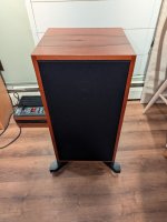
My NAD C372 have been in my possession for its last 7 years.
When I bought it it made a low noise, like tearing cloth slowly, when cold.
After like 5 minutes it was completely gone.
Now it never goes away. Always there, lurking in the silence.

The Mission:
I hope to get some guidance not only to fix this amp, but to upgrade it too.
Budget is hard to say when I don´t know what to change and to what yet, but let's say 150€-200€.
I´ll try to take pictures on things as I go, not only to make it easier for others to follow but because it's a lot more fun to read posts with pictures in them.
With a good help from you this can serve as a guide for future DIYers, with my lack of skill it can serve as a warning.
Let's hit it and see how it turns out!

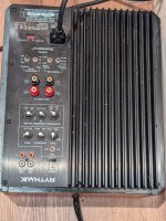
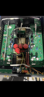
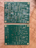
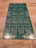
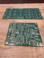
We'll start with the Main Board and the PSU. Later on I want to have a look at the Amplifier boards.
PSU.jpg

Main Board.jpg


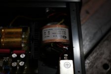
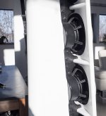
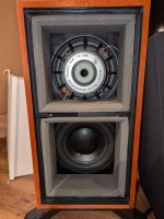
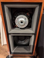
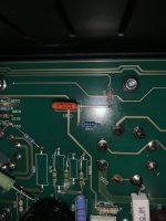
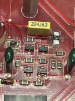
My first approach was to open it up and look for leaking or bulging caps.
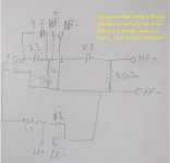
I found a lot of brown gunk around 4 bigger caps (bulk caps for rail B and C: C734, C735, C748, C749).
Since the noise is in both channels, the PSU seems like a plausible source of the noise in my noob head.
This is where it all started. Sourcing caps and info on what kind of caps I needed, aka opening Pandoras box...
I had a lot of problem with the small footprints and the 105C rating. The C372 is known for running hot so no 85C for me please.
Most HiFi-caps were too big since rail B and C clearly was designed by some engineer sharing closet with his wife,
while the main rail A was designed by previous mentioned wife.
After 3 days and 2 nights without sleep I ordered the best I've found:

2 x Vishay 2200uf 50V 105C with 7,5mm pitch (part# 2222 048 61222)
2 x Nippon Chemi-Con 1000uf 160V 105C with 10mm pitch (part# EKMQ161VSN102MP40S)
Cost: 20€

This is where I couldn´t help myself. I took another look into that box and soon realized that it's more fun to upgrade something than to repair it.
Invest money instead of just spending it so to speak.
I have no idea if these caps will solve my problem since it could be more bad caps.
I've also learned that not all caps bulge when they're bad, and that the brown stuff might be glue.
My idea here is to change most/all of the electrolyte caps (all branded Jinghai) to newer and better ones since they're all old.
(Are Jinghai good btw? In the computer world Chinese caps are not that welcome...)


We'll take a break here for some questions before looking at what to do with the main rail.

Any idea if I'm on the right path to solve the main issue, or do you think it´s something else?
Is it a good idea to spend money on upgrades, or should I first try to fix it first to be sure if it´s worth it?
Do I need to change other caps than the electrolytes, or does the film-types age better?
Should I change the film-types anyway for better sound?
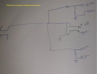
Piggyback small somewhat high-end caps to cheaper filtering caps to keep cost down or get smoother power, like a 0,220uF in parallel to C746 and C747 in C for example?

Hope you will join me in this one!

/F

FS: Pair of Peerless/Precision TX255F Vintage Woofers

For sale: Pair of Peerless/Precision TX-255F 10" woofers, from the 1980s.

attachment.php


attachment.php


Gray poly cone, new foam surrounds. Work perfectly. Great sealed box, infinite baffle, or open baffle driver. Here's the specs:

attachment.php


(BTW: These specs are in metric measurements. VAS is in cubic meters- multiply by 1000 for liters.)

Selling for $65.00 for the pair, plus shipping.

I don't have Paypal- I usually work with USPS postal money orders. US shipping only.

Thanks!

Regards,
Gordon.

Attachments

  • 3-21-16_peerless_tx255f_f.jpg
    3-21-16_peerless_tx255f_f.jpg
    167.2 KB · Views: 294
  • 3-21-16_peerless_tx255f_r.jpg
    3-21-16_peerless_tx255f_r.jpg
    157.5 KB · Views: 255
  • tx255f_thiele_small.jpg
    tx255f_thiele_small.jpg
    12.6 KB · Views: 235
Projects by fanatics, for fanatics
Get answers and advice for everyone wanting to learn the art of audio.
Join the Community
507,586
Members
7,878,383
Messages

Filter

Forum Statistics

Threads
405,784
Messages
7,878,383
Members
507,586
Latest member
kingburry