Updated Pass A40 Design

I've been having a look at Nelson Pass's A40 Class A design, that originally appeared in Audio magazine in the late 70's. I have done an update of the design that eliminates the tantalum capacitors and the need for the unobtainium Llambda power Darlingtons originally used in the design. This comes at the expense of discrete Darlingtons, but the ability to choose zippy updated bipolar driver and output devices, as well as being able to optimize the driver termination resistors may make up for the added complexity. All the parts should be available from the usual suspects. I'll post a prelim schematic when things quiet down for me a bit (3-5 other projects in the works). Of course I'm posting with the full realization that this is not strictly a Pass design any more, as so many aspects of the design have been changed.
  • Like
Reactions: rmfar

Eurotrip/parts search

Hello friends, I am starting a trip through some cities in Europe and I wanted to know if any of you know about electronics sales businesses for our DIY hobby, such as selling capacitors and resistors, even valves, etc. The cities that I am going to visit are Valencia, Madrid, Dublin, London and Edinburgh, any information is appreciated. In my country some spare parts/valves are quite difficult to find, and if they are available, sometimes it is at exaggerated prices. That's why I wanted to take this travel opportunity to take some things home. thank you very much friends

I have two Audioline 15W powered studio monitors, one needs servicing, need schematics for them.

Hi everyone,
I have a pair of Audioline 15W powered studio monitors, one of them needs servicing to fix intermittent distortion, I was wondering where I could find schematics for them online? they have internally mounted solid-state amplifiers in them, I'll see if I can post the model number later on today.

G.E. BA-5A audio delay line LTspice and other info

I happened to see the General Electric BA-5A limiting amplifier and that it uses an analog delay line to get the control voltage ahead of the signal, so nothing above a set level can get through. Reading the material on the web and in a book here, I started playing with LTspice to come up with the delay line using the same capacitance and induxtance, and tweak it for flat frequency response and also determine the time delay at various frequencies. It's by no means a complete treatment but there are three transformerless models and two with transformers. The transformers are not well-modeled, but I hope it will be of interest. Note that the book mentioned has just about the full theory section from the manual for the instrument as well as a great schematic. references are included in the document attached.

Because I prefer tube and other analog gear, and note that just about all compressors and limitiers have a finite attack time that can allow some excessive peaks through, this one is very interesting. I'm probably wrong about a lot of this stuff and just trying to understand it.

Attachments

Maybe a better way to cascade Linkwitz-Riley filters...

Been pondering IIR crossovers some more...always dangerous for me, being the die hard linear-phase xover dude I am...lol

Many are no doubt familiar with Linkwitz's cascading strategy found at https://www.linkwitzlab.com/frontiers_5.htm#V
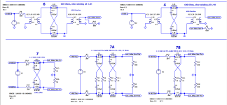
First from that link, it's shown how a parallel 4-channel topology has its issues, and that cascacading is a definite improvement.

1723226901113.png


Then next, the bold text in the snip below describes adding an all-pass to the SW (sub) channel based on the W channels low-pass frequency,
improves response further.


1723224195493.png


I think there is a better way, and not much harder to implement, ......particularly if you have an open-architecture processor than lets you place filters in series as needed.

Cascading high passes is retained....but the recommended SW all-pass gets dropped,
in exchange for putting all the low-passes used in higher channels, in series after a channel's principal low pass..

So for example, using the W channel which has a principal low pass at 200Hz. It gains a second low-pass in series at 2000Hz (The M channel principal low-pass).


1723225076607.png


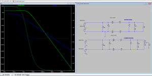
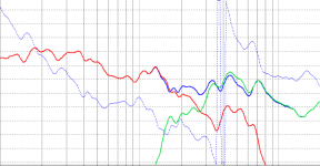
With the above flow put into a processor, here's the measured T+M+W+SW summation.

1723225853697.png


So zero ripple.
With no level adjustments, delays, or all-pass, on any channels.

Maybe there's holes in this.....i dunno..
again, i'm NOT an IIR man 😛

I figure the ripple free results can most likely be achieved through the use of more all-pass filters in series on the channels, akin to the low pass strategy I used.
But I'm like why bother with that?
When the low-pass strategy is so straightforward and simple....

Folks who do know IIR... please correct any/all of this if I'm barking up a tree (again LOL) ...thx, mark

Lase LF18-3600

Is anyone using these drivers? I have 4 loaded into 176l 30hz tuned reflex cabs.
The measured response is poor with a huge peak at 65hz and low output below 45hz but I believe the dsp in the plate amps I am using is the issue, once I get a proper amp I’ll measure them again.

Product Specifications:
  • Nominal Diameter: 18"
  • Power Handling (RMS): 1800 Watts
  • Power Handling (max): 3000 Watts
  • Impedance: 8 ohms
  • Frequency Response: 30Hz to 1,000 KHz
  • Sensitivity: 97.5 dB 2.83V/1m
  • Xmax : 13.5mm
  • Voice Coil Diameter: 4.5"
Thiele&Small Parameter:
  • FS: 41 HZ
  • Re: 5.5 ohm
  • Qms: 9.7
  • Qes: 0.41
  • Qts: 0.37
  • Mms: 247.4G
  • BL: 29.3T-M
  • Sd: 1216 cm2
  • Vas: 124.4 L
  • Weight : 42.2 Lbs(19.14Kgms)
  • Shipping Dimensions : 20.5" x 20.5" x 17.5"(533.4mm x 533.4mm x 457.2mm)

Soldering Iron Bit Problem

Just looking to see if anyone has had similar problems to me and if there are any experts that can offer advice. I’m using .5 mm Weller solder and a Weller WE1010 iron with a 1mm needle point bit.

The problem is my bit keeps losing its wetting and it oxidises and then will not solder properly. I’ve tried it at 350C temp and then 395C but it is still problematic. Any ideas? Thanks

IMG_0026.jpeg

Attachments

  • IMG_0024.jpeg
    IMG_0024.jpeg
    29 KB · Views: 110
  • IMG_0022.jpeg
    IMG_0022.jpeg
    695.5 KB · Views: 105

ADAM A7 Service Manual (including schematics) needed

Hi,

Have a fault with one of my Adam A7 monitors. Upon a visual inspection of the PCBs I have discovered a burnout component which I would like to verify. It's a small flat orange circular component which I think maybe a capacitor.

I would also like to get to the bottom of what has caused the component to "fry".

The PCB I am referring to is the right hand one mounted vertically as pictured (with white connector).

Any advice or tips people?

Thanks

Attachments

  • IMG_20240809_220450.jpg
    IMG_20240809_220450.jpg
    300.7 KB · Views: 144
  • IMG_20240809_220730.jpg
    IMG_20240809_220730.jpg
    237.7 KB · Views: 100

Alpine 7269 schematic

Hello I was wondering if anyone has a schematic for a Alpine 7269 cassette deck . This is a deck that I've been using in my 83 jeep CJ for years and it finally packed it in . I would just replace it with a newer deck but that would require cutting the dash and I want to keep the stock retro look and function. Turns out these early made in Japan Alpines are starting to become more valuable so figured I would see If I can salvage this one . thanks for any assistance Roger

Greetings

Greetings 🙂.

I'm new to building speakers and associated electronics. Just last Friday I fired up an Econowave I researched and built (inner damping and outer finish still to do) with assistance during wood sawing, routing and drilling from a friend. I am now in the process of putting together an amplifier.

Where to place high-pass filters?

Hi. This is probably a dumb question, but I'm cobbling together a pair of presence speakers using existing drivers and parts I have lying around.
I want them to operate only from 500Hz up, and I want to cross from the midrange to the tweeter at 2kHz.
I have a pair of existing existing 500Hz and 2kHz high-pass filters already built up from a different project few years ago, so should I take the 2kHz filter feed to the tweeters directly from the amp's full-range output, or daisy-chain it off the 500Hz filter?
Thanks.

New ldovr.com power modules (LT3045/LT3094/TPS7A4700/TPS7A3301)

Dear DIYers

Recently we have released a new revision of our regulators, please take a look

1. New Revision of Dual LT3045 PCB, 0-15V, 1A.
Now it is a bit smaller(24mm x 40mm), Heatsink friendly and can be paralleled for lower noise and higher current output.

3045-1AG-1200c.jpg3045G_heatsink.jpgparalleling_multipleLT3045-1200.jpg

2. Single LT3045 regulator board with fixed output 0-15V. 0.5A - same footprint (24mm x 40mm)

3045-0A5-1200c.jpg
3. Single LT3045 regulator board with configurable output 0-15V. 0.5A - 24mm x 40mm, the output voltage can be configured by DIP switch

3045-0A5M-1200c.jpg


for more details please visit www.ldovr.com

Best regards
and
Happy New Year

Hello from Slovakia

Hello everyone,

I am a technical university student studying software engineering. I do not have any proper education in physics or electronics, except for few courses, but I am more than willing to learn and take notes. Last year I have picked up electronics as a hobby, mostly digital circuits, but my interest in analog circuits is growing and is currently what I drain majority of my free time into. I am a proponent of open source and open hardware so I am looking forward to sharing my finalized projects with you on this site. Thank you for your time and I hope that I will fit into this community.

Greetings from Slovakia, enjoy your summer.

To display the album art of the playing music from the Tidal desktop app (windows) on an Arduino LCD.

I use TIDAL to listen to music. I don't use a dedicated network player, I use a Windows-based PC, and I use TIDAL's desktop app for Windows.

Like a typical network player, I wanted the case to display the album cover art of the current track when playing music from the TIDAL app. I used an Arduino and a 3.2-inch LCD to accomplish this.

Login to view embedded media
Since there is no official way to get information about the currently playing track in the TIDAL desktop app, I used window hooking to get the song title and artist, and then used this information to call the TIDAL API to get the album's cover art.

The obtained image is sent to the Arduino using serial communication. The Arduino displays the image received from the serial communication on a 3.2-inch IPS LCD. It's a slow process, but it's acceptable.

20240811_122135.jpg

Right way to simulate the EMI Filters? and load network

I was just trying to simulate the EMI filter now considering the Brookes Stability criterion had considered the values for the common choke with about 60mH.

Now was just doubtful about that is it right way to do the simulation with the loads. As I see differential version seems fine but common mode which is bottom circuit is something Im doubtful about.

the green curve is the differential mode output measured across R8 in the top circuit

the blue curve is the common mode output measured between the mid point of R2 and R6

Attachments

  • emi filter.PNG
    emi filter.PNG
    28.7 KB · Views: 74

Hi Everyone

Just thought I would start an introductory post, anyway, I just returned to the diyAudio forums after some time, I'm a long-time diy electronics hobbyist, I started out in diy electronics when I was 13 years old, I'm going to be turning 55 years old this month, and I still have the same level of interest in diy electronics as I did when I first started, I am currently living in Darwin NT Australia, it is a real pleasure to be a member of the diyAudio forum.

Greetings from Denver

Howdy folks, Big Willy here close to the Rocky Mountains. Happy to be here! I have some electrostatic speakers that I am trying to get sorted. Thought I would join and see what's what. Also interested in exploring Stax headphones and tube sound. If anyone has recommended electronic repair services close to Denver/midwest, please do share below in the comments. It is very hard to find good techs these days! Love the people who keep our gear alive and well.

Best,
UncleWill
  • Like
Reactions: rockies914

OB woofers query

Last month somebody posted a query on OB woofer mounting.
I've been itching to make another set of largish OB speakers for while utilising some old school Road Thunder 15" i have combined with the Jaycar 12" that are really only suitable for OB use [ Qts of 1.7] and I'm intrigued by the way they described the woofer mounting.
As per my attached sketch.
Blue driver being the Road Thunder and Red being the cheap Jaycars of which I now have an even half dozen but was going to use a quad but could use three per panel depending on what mids are used
My query is this. Is there a "Best Fit" set of angles for this way of adding in my big woofer?
I'd already contemplated a second box sitting beside the tall panel but this might work best for me.
I've already decided on angled wings and a 600mm wide baffle to suit the panels I have and I thought 300mm wings would work reasonably at 45degrees

Attachments

  • IMG_3084.JPG
    IMG_3084.JPG
    78.7 KB · Views: 83

Best used budget Stax system?

Really curious on the fuss for electrostatic ear-speakers. I have a pair of electret headphones (Stax SR-30) just to dip my toe in. All this talk about how much better true electrostatics are makes me curious. A few questions:
  • Does anyone have any thoughts on the best used Stax headphones?
  • Is there a better deal out there versus the SL-300 as an entry set of headphones?
  • Is there a difference in the sound of normal vs. pro bias electrostatics?
  • Any thoughts on the (now ancient) SR-5?
  • Tips for buying used electrostatic headphones? I believe that asking for sound balance is important.

Greetings From Seattle

Hello, Ben Smith here from Seattle. Long time audioholic beginning with a Marantz 2216b in 1979 - yes, budget friendly stuff 🙂 I've been lucky enough to move into Bel Canto DAC and amp, Meridian transport, Sota table and Vienna Acoustics speakers. More to the point of this forum, have built a couple of Bottlehead amps and am trying to design a 101D preamp as well as restore an APT Holman preamp. My other main distractions in life are photography and cycling, road and gravel. I'm also the winemaker, owner and bottlewasher of a small Seattle winery.

6.5” full range dip at 6K

Please feel free to move if better posted elsewhere.

Is this the expected handoff problem from mid to whizzer phase plugged with this driver?
Design problem(s)?
Recording/measuring error(s)?
All the above?

Drivers DA PS180-8
Hemisphere baffle internally lined with LOTS of silicone to minimize resonance problem(s)
Cabinet 42 liters/1.5cu ft good amount on cotton batting but not over stuffed
Rear ported (tuned at 80Hz) 4inch diameter 1inch length

IMG_7951.jpeg
IMG_7952.jpeg
IMG_8013.jpeg

Replacement tweeter for Fostex PM0.5

Hello all, thanks for having me in the group.

I'm after some advice on replacing a malfunctioning tweeter on a Fostex PM0.5 monitor.

It's just a single tweeter on one of the monitors that isn't working. I've done some online searches to find a replacement tweeter but it's a minefield for someone with limited understanding on these issues such as myself. I've got so far as to figure out its .75" diameter & 30watts.

Would this work?

https://www.cricklewoodelectronics....88KNYYez7FhrI7nkolfaaSDLS16M8J64aAjIMEALw_wcB

Any advice on which tweeter would fit/work correctly would be much appreciated .

Many thanks,

Jack

Attachments

  • PXL_20240810_080302948.jpg
    PXL_20240810_080302948.jpg
    255.9 KB · Views: 112
  • PXL_20240810_080315493.MP.jpg
    PXL_20240810_080315493.MP.jpg
    272.8 KB · Views: 74
  • PXL_20240810_080321049.jpg
    PXL_20240810_080321049.jpg
    378.5 KB · Views: 67

Watts Dissipated in xsim says what? and what impedance should my amp be at?

After doing a crossover build, making sure all the components don't exceed max power, got them shipped and speakers sound great! I wanted to see if I can turn the amp to max volume and what the speaker wattage would be. drivers are 7x 6.5inch 100w rms woofers and a single 80w rms compression horn. looking at the watts it says I'm getting over 1000 watts on the horn 700w amp? the speaker is 4.5 ohms. using a QSC gx5 amp (700w at 4ohms). thanks for any help in advance!

Attachments

  • circit.PNG
    circit.PNG
    23 KB · Views: 53
  • crossssing.PNG
    crossssing.PNG
    34.2 KB · Views: 53
  • elec_respons.PNG
    elec_respons.PNG
    23 KB · Views: 49
  • imp.PNG
    imp.PNG
    38.4 KB · Views: 53
  • wats_dissapated.PNG
    wats_dissapated.PNG
    29.1 KB · Views: 54

For Sale Stanton Stylus, NOS D5105AA for Stanton 500AA Cartridge

A buddy of mine sent these to me instead of throwing them out. He thought that he had given me two Stanton 500AA cartridges, but those boxes were empty. Anyway, out of the lot, I found one stylus that is NOS. The D5105AA made for the 500AA cartridge. Sale is for the one stylus only, but if you would like I will send the rest of the stuff along with it. Postage will be affected.
I am asking $15 + shipping for the D5105AA stylus.

Attachments

  • P8100006.JPG
    P8100006.JPG
    178.5 KB · Views: 44
  • P8100007.JPG
    P8100007.JPG
    215.9 KB · Views: 48
  • P8100009.JPG
    P8100009.JPG
    231.1 KB · Views: 43

Hello from Pure Music

Hey folks,

I have been an audiophile for some time and I have a nice little home studio with a couple of keyboards, guitars, cellos, and other instruments.

I'm a Denon and Focal fan for audio equipment, and found these forums while looking up information on DIY speakers, as I'd like to experiment and upgrade that way if I can learn how.

Hope I get to learn a lot from you fellow audiophiles and DIYers!

- puremusic

AWW-DSC09131_-_Copy.jpg

Some measurements of port compression using 15TBW100

´I have remade the ports for my DIY subwoofer with a 15TBW100 driver. The ports were previously undersized (two round 103mm ports, 164mm² port area), the tuning frequency was about 32.5 Hz with a net internal volume of 100 liters (~3.5 cu ft). The undersized ports had a 14mm radius flare on both ends.
The new rectangular ports have a total 296mm² area and a 55mm flare radius on both ends, but they sit directly against the bottom and walls, so only 2 of 4 sides of the ports are flared. The tuning frequency increased to 38.5 Hz, and the net internal volume is now 81L, due to the larger ports.
I've made frequency response measurements of the subwoofer at different power levels before and after the changes using UMIK-1 (6db gain) and REW, and put together some port compression data in a spreadsheet.
All measurements are ground plane 2m. Velocity in m/s and compression in db.

1723295779293.png

The spreadsheet shows input voltage, WinISD simulated port velocity and measured compression compared to the 5.66V sweep for Fb - 2.5 Hz, Fb, and Fb + 2.5 Hz. It also shows compression at 130 Hz (low impedance) in order to get some indication of possible power compression, depending on sweep level.

Some things I found interesting:
Port compression mostly affects frequencies below Fb. The undersized ports had only 0.7 db port compression at 77,9V and 35Hz, despite a (very high) simulated port velocity of 36,3 m/s.
Power compression at 130hz was considerable, although later in the sweep (more time for the voice coilt to heat up), it means that power compression likley affects the high power sweeps. For instance, there is more compression at 41Hz, 112V after the mod, than at 35Hz, 77,9V before, despite lower port velocity (28,3 vs 36,3 m/s).
  • Like
  • Thank You
Reactions: GM, freddi and stv

Hello from New England...

Hi All...

I'm new to the Forum and enjoy everything from home theater to car stereo. Music has always been a part of my life from back in the day when we used to carry those big things called boomboxes LOL and making mixtapes as a hobbyist DJ. From there it led to the ride having good sound system and the best speakers I could afford... I think they were Pyle Drivers 🤔. That carries on all the way into my midlife years, where I like my sound always sounding crisp and clean.😎

Thanks... J

Hello from Dorset, UK...and some advice on Fostex PM0.5

Hello all, thanks for having me in the group.

I'm after some advice on replacing a malfunctioning tweeter on a Fostex PM0.5 monitor.

It's just a single tweeter on one of the monitors that isn't working. I've done some online searches to find a replacement tweeter but it's a minefield for someone with limited understanding on these issues such as myself.

Any advice on which tweeter would fit/work correctly would be much appreciated .

Many thanks,

Jack

Attachments

  • PXL_20240810_080315493.MP.jpg
    PXL_20240810_080315493.MP.jpg
    272.8 KB · Views: 36
  • PXL_20240810_080302948.jpg
    PXL_20240810_080302948.jpg
    255.9 KB · Views: 33
  • PXL_20240810_080321049.jpg
    PXL_20240810_080321049.jpg
    378.5 KB · Views: 31

Revox B150 problems

Hi to everyone,

I'm trying to repair my Revox B150 amp.

When I connect it to the AC mains nothing happens except for:

. the "Speaker A", "Speaker B" and "Remote" leds on front panel light up;
. after few seconds, the speaker relais switch on.

All the sections (transformer, power supply board, preamp board, phono unit, input/output unit, power amp board) are ok except for the microcomputer board.

Especially, it seems that the microcomputer IC1 (HD63A01V1, rel. 1.725.290.07) and IC2 (PCF84C81, rel. 1.725.290.05) have serious problems, but it's very difficult to me to detect the fault in a more precise way.

Is it a common problem? Any idea about any further investigation I could perform? Where (except for the very expensive Revox jewelry) could I find those ICs?

As usual, thx a lot in advance to everyone

For Sale Tannoy SPM-P0CA9 tulip tweeter

Unused, new and i factory box. This is the smaller tulip diameter version, with smaller magnet. With ferrofluid, ready for use.

Gotten as one of two left over in Tannoys storage facilites in 2023, through Lockwood in the UK.

Don’t need them as I restored my 3134 tweeters, plus diameter and magnet is smaller than the 3134 tweet. That said, it does fit the 3134 assembly.

Asking 250 Euros plus shipping (less than I paid myself).

Dunno the exact DC drivers these will fit in/be perfect for, I will leave that up to you.

Regards,
Andy

Attachments

  • IMG_1847.jpeg
    IMG_1847.jpeg
    326.6 KB · Views: 55
  • IMG_1846.jpeg
    IMG_1846.jpeg
    426.2 KB · Views: 52
  • IMG_1848.jpeg
    IMG_1848.jpeg
    542.1 KB · Views: 46
  • IMG_1849.jpeg
    IMG_1849.jpeg
    597.2 KB · Views: 46
  • IMG_1850.jpeg
    IMG_1850.jpeg
    525.8 KB · Views: 49

2channel amplifier module for speaker (with DSP)

Hello,

I was looking to build a speaker but to my surprise the Crossover parts have become really expensive (one Crossover would cost 75€).

Now I am seriously considering using a 2 way amplifiermodul with a DSP instead.

The speakers have a Seas DXT tweeter (55W RMS) and a wavecore 182 woofer (85W RMS).

While looking for amplifier modules I found that they all seems to have equally powerful channels. Is that a problem? Because I assume the tweeter channel will run at much lower power than the woofer channel.

would you recommend using a two way module for each speaker and integrate it or rather use an external amp?

Thanks 😊

For Sale New Bulk Pomona BNC 12" Cables

SOLD - Thank you.

I've stopped buying cheap cables - the results are not worth it. Recently I bought a large number of Pomona cables in different lengths and terminations.

These new 12" Pomona 5697-12 BNC cables are excess to my needs. New price is around $13 each plus shipping.

2 cables - $20 shipped to the CONUS only, including shipping in a padded envelope, and PP fee (about 4%).
4 cables - $38 ""
6 cables - $57 ""

Thank you

gktaudioPomonaBNC12.jpg

CSS Detroit DIY Loudspeaker GTG...

Copied and pasted...

CSS Detroit DIY 2nd Annual DIY Loudspeaker Get-Together (Sept. 28th, 2024)

Yesterday, 12:23 PM
Ok guys, the conference room is officially booked at the following location:

Home 2 Suites by Hilton Northville - Detroit
47450 W Five Mile Rd
Northville, MI 48168

This will be Saturday, Sept. 28th from 9am - 6pm for the usual show 'n' tell. Each speaker gets 5 minutes of house music plus 5 minutes of your music.

Hope to see you there!

DanP

For Sale AN39 8/4R Boards and Class A PSU Classic diode

Login to view embedded media The sound of one only channel....
The journey of building my AN39 amplifier is over, everything went wonderfully.
I would like to give the opportunity to those who want to build this amplifier the rest of the mine boards are available.
Also power supply boards class A with classic rectifier diodes STPS20M60D and Cap multiplier to reduce cost relative to LT4320 .The ripple at 2.6A its about 1-3mv
Pm please .

Attachments

  • IMG_20240324_094404.jpg
    IMG_20240324_094404.jpg
    420.8 KB · Views: 145
  • IMG_20240324_095116.jpg
    IMG_20240324_095116.jpg
    432 KB · Views: 141
  • IMG_20240617_210822.jpg
    IMG_20240617_210822.jpg
    469.1 KB · Views: 131
  • IMG_20240617_212204.jpg
    IMG_20240617_212204.jpg
    371.6 KB · Views: 122
  • IMG_20240625_155216.jpg
    IMG_20240625_155216.jpg
    449.5 KB · Views: 110
  • IMG_20240617_210751.jpg
    IMG_20240617_210751.jpg
    488 KB · Views: 102
  • IMG_20240617_210803.jpg
    IMG_20240617_210803.jpg
    326.3 KB · Views: 93
  • IMG_20240617_210812.jpg
    IMG_20240617_210812.jpg
    330.3 KB · Views: 98
  • IMG_20240617_211856.jpg
    IMG_20240617_211856.jpg
    330.5 KB · Views: 110
  • IMG_20240323_215012.jpg
    IMG_20240323_215012.jpg
    253.1 KB · Views: 77
  • IMG_20240323_214918.jpg
    IMG_20240323_214918.jpg
    252.6 KB · Views: 71
  • IMG_20240419_230836.jpg
    IMG_20240419_230836.jpg
    439.1 KB · Views: 70
  • IMG_20240326_103218.jpg
    IMG_20240326_103218.jpg
    321.5 KB · Views: 75
  • IMG_20240322_121700(1).jpg
    IMG_20240322_121700(1).jpg
    473.8 KB · Views: 86
  • Like
Reactions: ItsAllInMyHead

Experience with AS395H as MAT03 replacement

I was wondering if someone has experience with using the AS395H as a substitute for the MAT 03?
Is the AS394 a mossible substitute for the MAT 02? I believe it is known as a substitute for the LM394.
Or if somenone has a suggestion as a replacement for the MAT02 I would like to hear it.

I see pro-audioparts has the SSM2220 but is manufactured by MIDAS. The originals were buy Analog devices.
Any thoughts on this.

Please help identify vintage transistors

G'day mates,

from a recently acquired shoebox full of vintage transistors, there are a few (house-numbered) types I'm not able to (fully) identify - I would appreciate any info you may have on these:

TO-66
  • 6-140, NPN, going by an otherwise unrelated google hit, 274 is the MIL MFG code of RCA (the case style seems to support that); going by the case style alone, 185 could be Motorola
  • 6-5909, PNP, Motorola (?)

TO-3
  • 6-5675, NPN Darlington, Motorola
  • 6-6937, NPN, MIL MFG code 980 (?)
  • 65826, NPN, RCA, found one reference of this one being used in Applied Digital Data Systems' CRT display terminals Consul 520, 580 and MRD 380
  • 7-4503, NPN, Motorola / RCA
  • ESM2668BP, NPN, Sescosem / Thomson, I have the base data for ESM2668, but would like to find out what the BP suffix stands for, if anything
  • NCR8-05, NPN, Motorola, this may be a lucky coincidence, but are these just house-numbered BD130 as suggested by the Siemens part...?
  • TE432, PNP Darlington, Motorola

The ones in the second picture I have the base data for, but would like to find out what their suffixes mean:

  • 2N3055 P, Fairchild, what does the P stand for?
  • BDX61T, S (?), what does the T stand for?
  • BU208G, Motorola, I know that G on the more recent onsemi parts indicates they're lead-free, but did Motorola use that convention in 1982 already...?
  • BU500V, Texas Instruments, what does the V stand for?
  • BU800S, Motorola, what does the S stand for?

Please note I don't really care if these can actually be used for anything worthwhile - I know that at least some of them are horizontal deflection / output transistors, so pretty much useless. But I would still like to find out some more information about them, just to satisfy my curiosity. 😊

Thanks a million!

Attachments

  • 20230106_143606_2.jpg
    20230106_143606_2.jpg
    453.4 KB · Views: 305
  • 20230101_141240_2.jpg
    20230101_141240_2.jpg
    362.7 KB · Views: 223

How to damp Sziklai oscillation?

I am having trouble with a phono stage where the gain stages are Sziklai pairs. I have built these before without trouble but this time I am getting bursts of oscillation. There was no problem initially, but developed after running it in for about a week, which I find very confusing. The transistors in each pair are bc337 and bc327: perhaps these are unsuitable? I can find no consensus about how to address the problem; maybe a small cap to ground from Q2 base or an RC in the same place? There is maddeningly little information on Sziklai pairs in textbooks!

Mega midbass straight horn 139dB

I think I nailed this but perhaps I made some mistakes and more can be wrung out of this driver or another drive can get similar results at lower cost.

The aim is a midbass horn covering 100 - 400 Hz that can keep up with a community M200 on a clone of a K-402, or is that's a bit challenging a classic dual conical CD horn. The midbass will be the same width as the K-402 (1m) and will also be a rectangular horn. The aim is to make a 3 way full horn stack that can keep up with the M200 and has low distortion. The driver used is the Beyma 15p80fe/n as it has very low Qes and high power handling and 7.5mm xmax. I selected an exponential flare as it should provide the highest fidelity.

I used the papers of Keele to design the horn:
The throat is sized for maximum acoustic efficiency, the mouth size was selected to be optimum and the rear chamber is sized for reactance annulling at 100 Hz.

Attachments

Audia Flight One schematic or service manual needed

I'll give it a last shot.
Working on an Audia Flight One integrated amplifier that puts 1.7 VDC out on left channel output.
Build as a dual mono amp, however due to design/layout of interconnects and control wiring, it's impossible to make measurements / comparison measurements with the circuit in place and powered on.
I desoldered and measured all transistors/fets manually and with the DCA75 component tester, and replaced a single questable fet, but with no luck. All other components and soldering looks fine......
Any help appreciated and thanks in advance.

IRS2092 Heat Dissipation?

So I am working with some of these guys here:

IRS2092.jpg


I just started some of my testing of this module.

I already did the R13 resistor replacement (mine was 100R, replaced with 3.3K) to bring the gain down. Did this before even hooking up to bench test.

I got this running from by bench power supplies (so I could limit current if anything went wrong) at +/- 64 volts exactly. I actually have TWO of these little modules running.

But I noticed: even idle, they run a bit warm. It was late and I did not break out a temp probe or the temp gun, but not only are the heat sinks warm - but the entire PCB is rather warm on the backside. If I had to guess, I would say the PCB backside is upwards of 100-115 degrees F.

Class D amps are supposed to run cool, no? lol...

Next thing I noticed is this: one amp seems to idle warmer than the other one by at least 10-15 degrees F. They are literally both connected to the same power supply. Should I be concerned?

Final thing I noticed: one amp has a bit more hiss than the other. Again, not that this will matter much: these are destined for subwoofer duty - so not gonna hear much hiss from a 10" sub anyway.

Finally... regarding that heat. I am thinking of picking up some heat sink stock, see here: https://articulo.mercadolibre.com.m...lor-aluminio-negro-76cm-ancho-12-mt-largo-_JM

That heatsink is about 3 inches wide, 3/4 inch thick and 4 foot long. I was thinking of removing the MOSFETS from the top side and carefully rotating them to the backside (180 degrees), mounting them w/ mica insulators directly to the heatsink and then mounting the PCB to the heatsink with nylon standoffs. My plan was to cut off two 12 inch long sections of that heatsink and so each of the two amps would have a dedicated 3" x .75" x 12" chunk of heatsink. The big question here is: would this be enough for passive cooling?

Last question - the IRS2092 chip itself. I noticed it has a small aluminum chunk that bridges it to the heat sink currently. As I understand, this chip also generates some heat. Since I would be re-locating the primary heat sink to the back-side, the IRS2092 chip will need some heat sinking as well. I have some small self-adhesive (.5" x .5" x .25") mini heat sinks I often use for low-power LM317 applications. Would one of those stuck to each IRS2092 chip be enough? Or would something larger be required?

Each of these amplifier modules will only be driving an 8 ohm load, so nothing too crazy.

-Dean

Mark Levinson 33H calibration

Good evening,
I recently came into possession of a pair of Mark Levinson 33H power amps, which are quite battered. The restoration and restoration process has almost reached its end, but it is not clear what the correct calibration values for the bias and power supply voltage of the preamplifier boards are. I am not even able to establish the settings of the oscillator board.
Does anyone have the service manual? Or do you know who to contact to get it (for a fee of course). Here in Italy it seems impossible even through the official importer.
Thanks to anyone who can help me

Power amplifier advice needed

I want to buy a power amplifier but need to figure out my power requirements and it's rather confusing. We have 4 speakers that are 450 watts each with an impedance of 8 ohms. I want a 2 channel power amplifier. Should it be 900 watts, twice the speaker watts? Does it matter how the speakers are connected to the power amplifier? I see talk about parallel vs series connections. This is for a small village church in Indonesia that I'm trying to help.

Dual AKM 4990 Board from Aliexpress - Problems and help required!

Hi Eveyone,
I'm a newbie here. I've got a dual AKM DAC board which I purchased some time ago from Aliexpress and have only just gotten around to powering up. I've partially built the enclosure up and i've tested the power supplies are delivering the correct voltage to each of the terminals. However, i'm getting a blank screen on the LCD panel (although it does light up) and the selector switch does not seem to scroll through inputs like it should. I've also connected a digital source via coax and I get no sound at all. Not sure where to start looking for possible issues, but if anyone has any ideas i'd be grateful. I've tried contacting the seller on Aliexpress, but I purchased this a while ago and am expecting to get a brush off if I even get a response at all! Photos attached. Note that there is an LED on the back of the display screen which isn't lighting up, but not sure if this only lights when a remote control IR is detected (my board didn't come with any remote).

Anyone got any ideas? Thanks in advance!
Andy.

Attachments

  • IMG20240713101806.jpg
    IMG20240713101806.jpg
    400.7 KB · Views: 150
  • IMG20240713101818.jpg
    IMG20240713101818.jpg
    375.5 KB · Views: 148
  • IMG20240713101757.jpg
    IMG20240713101757.jpg
    245.8 KB · Views: 152

Is Fs a stand in for distortion?

In another thread I posted my theory of using Fs as a guide for the lower cut off of a driver such as a tweeter or midrange. I posited that it's not so much the Fs we care about but distortion. Unfortunatley most manufacturers don't really post distortion specs.

The esteemed @AllenB posed the question as to whether or not this was really true and honestly I'm not really sure! 🙂 so I thought I'd ask. In a couple of drivers I've looked at this seemed to be a good rule of thumb. Take the plots from the Scanspeak 4" Illuminator 12mu/8731T00:

1723168449908.png


I happen to also have the distortion graphs from Zaph:

1723168516207.png


If this pattern holds then using a general guide of 2x FS is not a perfect substitute for distortion but it's not a terrible method either. As mentioned, I've not written an academic paper or thesis on the topic but to me it's fair to say this is a useful guide in the absence of all other data. The impedance can always be flattened, but not the distortion.

What do the more experienced members think of the statement?

Best,

Erik

Cheap ARM MCUs for RBCD audio

ARM Cortex M0 series CPUs have been around for about a decade now but, unlike their bigger siblings (M4, M7), don't come with I2S interfaces at the cheaper end of their product ranges. I decided to have a go at re-purposing the SPI interface which comes as standard on many low-end parts for I2S duty.

Over on Aliexpress you can find STM32F030-based boards for around $1 which have the necessary SPI interface. While its certainly cheap, the F030 is getting a bit long in the tooth now and has been superceded by the G030 which hopefully eventually will fall to the same (or lower) price as the F030. The G030 is a little bit more powerful (64MHz vs 48MHz) but more importantly is much lower power and also has a single I2S port. Even with the very welcome addition of the I2S port though you'll still need the SPI interface as the manufacturers in their wisdom only implemented a half-duplex I2S. Which means you can either use it for input, or output but not both.

To get started in programming the F030 you'll need to download a toolchain. ST has a helpful package called CubeMX which allows initialization of various peripherals by 'wizard', i.e point and click. After setting those up it generates code which users add their own individual elements to. In order to edit and augment the machine generated code, I use Keil's MDK which is free provided you're not generating more than 32kbytes. I avoid C as much as I can, preferring the embedded assembler capability. A debug probe is also a requirement - I use the debugger part of an STM discovery board which has been reprogrammed to emulate a Segger J-link. This handles programming the chip as well as debug functions such as single stepping and breakpoints.

I'm attaching the schematic of the I2S->SPI interface which uses a handful of 74HC logic. Based on previous experience with an LPC1114 (also a Cortex M0) I reckon a 48MHz M0 can likely handle a 2X oversampling stereo FIR filter with a length no more than 90 taps or so. The G030 may well be able to deal with up to 120 taps. To go longer a second MCU could be used in dual-mono configuration or overclocking would be another option. Going beyond those options would probably require higher precision in MACs though so probably will be better suited to an M4 or even an M7.

As a sub-project on this thread I'd like to develop a plug-in replacement for the venerable old SAA7220 using the STM32G030. As far as I know, these are the only commercially available dev boards other than the official ones from ST : STM32G030???STM32G030C8T6????Cortex-M0??G0???STM-???

Based on the DS for the G030 the power draw should be under 50mW vs around 1W for the SAA7220, a 95% saving.

Attachments

  • I2StoSPI.jpg
    I2StoSPI.jpg
    181.9 KB · Views: 1,155

Different drivers in common inner housing

In the case of multiple drivers in a small enclosure, it is often not feasible to give each driver its own enclosure. If the drivers are identical and controlled identically, this is not a problem. With drivers of different types it is less clear. In the attached pdf a method is proposed to deal with this situation.

Attachments

Projects by fanatics, for fanatics
Get answers and advice for everyone wanting to learn the art of audio.
Join the Community
507,583
Members
7,878,245
Messages

Filter

Forum Statistics

Threads
405,783
Messages
7,878,245
Members
507,583
Latest member
Mark in PDX