Mute Circuit Class 4 clone

I have a CT Sounds 2000.1 class 4 clone. I Need some help with the mute circuit. This one is staying high on Pin 3 of the driver board.

I have working driverboard I swapped in with the same results.

Driverboard has a njm4560, lm219, and mmhc74m which all have been replaced.

Inductor has been replaced. Original was cooked.

Power section and audio section had failed in this originally.

Drivers and mosfets replaced in both sections.

Optocouplers were replaced.

all 3 of the 5v regulators are within tolerance.

driving an 80hz square to the driveboard i can see on pin 1.

I was able to verify the drive in the output section before I put the rectifiers in.


Driverboard voltages:
1. -.848v
2. .07v
3. 10.22v
4. -11.40v
5. 11.40v
6. .154v
7. .154v
8. .06v
9. 5.04
10. .300v
11. .300v

Attachments

  • 20240818_153651.jpg
    20240818_153651.jpg
    289.4 KB · Views: 46
  • 20240818_153612.jpg
    20240818_153612.jpg
    207.8 KB · Views: 44
  • 20240818_153545.jpg
    20240818_153545.jpg
    407.7 KB · Views: 41
  • 17240140823772823786348556065314.jpg
    17240140823772823786348556065314.jpg
    379.1 KB · Views: 41

TPA31xx custom design questions

Hello everyone,

This is my first audio project. Last few days I have been putting together a schematic as well as a BOM for a TPA3128D2 based class D amplifier. Most of the design is taken from the TPA3128D2 datasheet "Typical Application" at page 23 and TPA3116D2 EVM User's Guide (Rev. B) "TPS3116D2EVM Schematic" at page 5 as it is the same as TPA3128D2 Evaluation Module, but includes the schematic and the PCB layers are more readable. I have also included the anti-pop from 360customs and volume control that follows wiring shown in the attached image. The materials of different capacitors are determined by what I gathered from reading through different forum posts.

I am attaching my unfinished schematic. I have multiple questions regarding the design, but I am going to address them one by one in different posts in this thread. What I want to open this discussion with is whether the EMI C-RC snubber (see attached image) is necessary and what is the advantage of including one. Is the advantage audible?

To give you more insight the power supply used is 24V 6.5A, gain is set to 26dB and the speakers are a pair of older 35W 4ohm Pioneer S-P170's.

For the initial post this I believe should suffice, I would like to keep it concise so that it does not deter one from reading the post. Thank you to everyone for reading and responding.

Attachments

  • volume_control.jpg
    volume_control.jpg
    41.3 KB · Views: 81
  • tpa3128d2_class_D_unfinished.png
    tpa3128d2_class_D_unfinished.png
    121.3 KB · Views: 77
  • tpa3128d2_class_D_unfinished.pdf
    tpa3128d2_class_D_unfinished.pdf
    88.1 KB · Views: 51
  • EMI_C-RC_SNUBBER.png
    EMI_C-RC_SNUBBER.png
    32.5 KB · Views: 85

DIY spherical ESL

Moving this from the thread on DIY spherical speakers...

For those who haven't seen the previous posts, I am looking at using a 3D printer to produce a "spherical" ESL with 12 drivers about 200 mm in diameter each arranged on the surface of a truncated dodecahedron. The printed parts will serve as structural elements as well as the stator supports for wire screen stators unless I can find a cheap source of perforated sheet metal discs. Diaphragms will be 6 um polyester with Licron coating.

The diaphragm side of the printed parts will print on the printer's bed so they will be smooth and flat. My printer has a 300x300 mm cast aluminum tooling plate bed with a layer of PEI. I am planning to use ABS to print the actual speaker parts and will solvent weld them together using acetone. I have printed some 100 mm stator pieces and a gluing jig to test the accuracy of the printer.

Today I redesigned and printed the gluing jig for the smaller test build before I commit to the full size speaker build, and welded one hemisphere together. I used ethyl acetate (sold as MEK substitute) to solvent weld the 3D printed PETG parts together. As I was gluing it occurred to me that the jig may not be necessary- strategically placed binder clips might do the job just fine. It takes just a tiny drop of the solvent and the joint is secure in a less than a minute.

When I set the glued up assembly down on a flat table all the surfaces on the bottom of the assembly touch the table so I think the printer is producing the prints with accurate angles. The surfaces that are welded looked like they were parallel to each other. I will print the other 6 individual stator pieces and glue them together and see how the two assemblies line up. Then it will be on to more of the design work for the actual drivers.

Note- the print quality is less than ideal- I have a 1mm nozzle on the machine so retraction doesn't work worth a damn resulting in blobby defects. I'll probably switch to a smaller nozzle where I can use retraction effectively for the final prints.

This is a truncated dodecahedron:

Screenshot 2024-07-24 204142.jpg


Three of the outer stators pieces (red) in the gluing jig (blue). The orange piece is one of the inner stator pieces:

Screenshot 2024-07-24 202943.jpg


Here is a hemisphere made from the small, test-sized outer stator pieces:

hemisphere.jpg


It will be interesting to see if the diaphragm tension causes the stator pieces to flex out of shape. I'll probably add some supports for the wire screen to the inner and outer stator pieces, as well as some means to add dust covers to each driver using the same 6um film as the diaphragms. I still have to work out details of the electrical connections.

aleph 0 biasing

Hi Folks,

Got Aleph 0 from a friend to overlook. Figured out it needs dc re-adjusting and rebiasing. For DC offset it is quite clear, the right pot does the thing. But I am feeling a bit lost with biasing. I understand the left pot is setting the bias, but what is the best way to measure? Points and values, if you don't hesitate.

Thanks in advance.


IMG-3560.jpg


IMG-3561.jpg

NAD C 525BEE strange skipping...possibly solved

Hi!

Another NAD-issue here but hopefully solved by now. I guess skipping is more or less strange (and annoying) when it happens.

However, this one didn't make any sense due to the following:
- The C 525BEE quickly handled all my (troublesome) CD/CD-R/CD-RW's without any issues plus is remarkable resistent to movement during playback...not
at all like a player that struggles to read due to a weak laser...

And now the issue, many longer CD's (>=40min) started to skip towards the end.

Well, I opened the little bugger and while everything looked very nice:
PXL_20240818_175216065.MP.jpg

However, after using it for a while I noticed the following little "collision" between the white flat ribbon and the black AC wires from the transformer. (Fixed in these photos).
The "collision" took place at the red markup below:
PXL_20240818_173358686.MP~2.jpg

After moving the AC wires away they are never close to each other anymore and haven't heard a skip since then.

Could this really have been the root cause for the skipping - I hope so anyway and I'm a happy NAD CD listener now 🙂

/Per
  • Like
Reactions: huggygood

Musical Fidelity F16 problem/Schematic

HI All
Little problem with a Musical Fidelity F16 power amp.Keeps coming through distorted on one side and occasionally completely cuts out.Takes a while to happen suggesting temp related but if you raise the input level it cures it possibly suggesting a dodgy capacitor somewhere.Have checked for dry joints.Also does anyone have a schematic for the above.Musical Fidelity will not sell me one.Thanks for any help.Smiffy

Low Budget 2 way speaker

Hi everyone, it's good to be here!

I'm planning to start my next speaker-building project. After building two pairs of full-range speakers (Dayton and Fostex), I would like to move on to a two-way bookshelf speaker.

I'm looking for recommendations on parts combinations for a two-way speaker with a budget of 650-800 euros for all parts (drivers and crossover).

It would be great if the recommendations are based on your experience and if you could suggest a ready-made or kit crossover.

I'll try to specify my requirements to help get accurate recommendations:

1. Room Size: I plan to build these speakers for a small room, around 25 m², so I guess they're near-field speakers.

2. Enclosure Size: I would like to limit the size of the speakers to 40x60 cm.

3. Materials: I think it will be easier with plywood, though I would like to try solid wood such as oak, ash, or walnut, and possibly 3D-printed parts if a horn or port is needed.

Thank you, and have a nice day!

Avi

  • Locked
Whammy Amp builder with quick question

Hi everyone,

I'm an absolute beginner that is nearly done my first build of any kind and I'm realizing that I'm missing a 2.2k resistor, no doubt I lost it myself. Can I replace it with any 2.2k resistor? Does it need to be 'audio grade', or also Dale to match all the others? If I can use a different brand, should I de-solder the one that's already in so that they match?

Thanks so much, this has been so much fun. I'm also very nervous(excited) to see the end result.

Appreciate getting a peek into your community and your expertise.

Project Ryu - DIY Field Coil Loudspeaker

Hello,

***First i want to say I'm not sure if i should post this under Fullrange or Multiway. Since at this point, there is a high posibility of the need for a supertweeter i chose Multiway forums. I won't mind tho if moderators think it's more suited for Fullrange forums.

About 6 months ago, i started thinking about a DIY fieldcoil speaker. I know opinions vary quite a lot on this matter and so i will do my best to offer as much data as possible for things to be judged objectively. Since that time I have been talking with some fellow countrymen and audio enthusiasts about this project and these conversations helped me in making some of the design decisions. The work is still in progress and i hope your opinions and comments can help tune it to higher performance.

To begin, here are the basic aspects about this project:

- field coil underhung motor structure
- 12" diameter
- Wide range (up to 10kHz), hopefully fullrange (up to 20kHz)
- high efficiency
- to be used in BLH

My personal taste in sound is that i like it when it comes out of large radiating surfaces. Large SD, large horn mouths etc. I think it's a necesity when one tries to reach real, live music levels and at the same time keep a good response to instruments' attack, sustain and decay. This is the reason i chose 12 inch diameter. I would've liked 15" better but it would've been too difficult to make it wide range. Perphaps a future project.

Field Coil Motor Structure:

I have spent a lot of time looking for other field coil projects, for any information on FC design or about available products and i have to say there isn't

much out there. From the pictures of opened FC units i could see a basic shape of the pole pieces. I have to say this is amongst the first design issues i encountered, there isn't much freedom to design these pole pieces, not like the case with permanent magnets anyway.
The next thing one can notice is that the new FCs are low impedance type and this is easily understandable. I have decided that my field coil will also work with 12-15V supply.
Underhung design means thick top plate. Of course this will cause a drop in flux density in the gap. The compromise here i found to be between flux density value and voice coil excursion. Since this speaker will mostly be used horn loaded i sacrificied Xmax to make a thinner top plate. I use standard 1010 steel with a maximum of 0.13% carbon, the best i could get my hands on.
I ran simmulations in FEMM for different values of top plate thickness, FC's number of turns, dimension, wire diameter etc. Here are the results i stopped at:

- magnetic gap height: 12mm
- magnetic gap width: 1-1.5mm
- 5.3 ohm FC 1400 turns of 1.25mm copper wire

Below you can find a rather crude sketch of motor structure:

FC_Structure01.jpg


Here are some results from FEMM analysis:

I ran simmulations with 1010 steel as well as 416 steel (has slightly more carbon typical 0.15%) to see the differences.

FC_Field_h_C_2_2_Amp.jpg

FC_Field_LC_2_2_Amp.jpg


1010 Steel Curve over 20mm and 12mm:

FC_B_LC_2_2_Amp_20mm.jpg

FC_B_LC_2_2_Amp_12mm.jpg


416 Steel Curve over 20mm and 12mm: (actually the curves are smoother had to lower resolution a bit because of my computer)

FC_B_h_C_2_2_Amp_20mm.jpg

FC_B_h_C_2_2_Amp_12mm.jpg


Magnetic gap:

FC_Field_gap_LC_2_2_Amp.jpg


AS it is, at 2.2 Amps we have 25W for the FC. I don't expect to have too much trouble with heat at this power. Test will tell tho, depending on how well the metal does the job of sinking the heat. The value predicted by FEMM lies around 1.6 Tesla. In reality i believe this value will be smaller 1.4-1.5 T. In tests i will drive the FC with 3 amps and see how much it heats up.

In this design the gap width is 1.5mm. Somewhat large, I'm thinking to add a 0.5mm thick copper ring right in the gap (yellow part from picture below). Now
it's true i have never seen a picture with a FC unit having a faraday ring and I'm not sure if it's necesary. I guess the FC itself has a role in that too.

Gap_faraday.jpg


I'm also making a 1mm gap variant (without copper ring) in hopes to get more flux density. The FEMM simmulation shows:

FC_1mm_gap.jpg

FC_1mm_gap_B_high_res.jpg


Here are some parts of the magnetic structure after machining:

DSC02849.jpg

DSC02854.jpg

DSC02857.jpg

DSC02858.jpg

DSC02863.jpg

Attachments

  • FC_Structure01.jpg
    FC_Structure01.jpg
    623 KB · Views: 632
  • FC_Field_hC_2_2Amp.jpg
    FC_Field_hC_2_2Amp.jpg
    199 KB · Views: 525
  • FC_Field_LC_2_2Amp.jpg
    FC_Field_LC_2_2Amp.jpg
    185.2 KB · Views: 483
  • FC_B_LC_2_2Amp_20mm.jpg
    FC_B_LC_2_2Amp_20mm.jpg
    41.7 KB · Views: 424
  • FC_B_LC_2_2Amp_12mm.jpg
    FC_B_LC_2_2Amp_12mm.jpg
    40.3 KB · Views: 452
  • FC_B_hC_2_2Amp_20mm.jpg
    FC_B_hC_2_2Amp_20mm.jpg
    39.7 KB · Views: 431
  • FC_B_hC_2_2Amp_12mm.jpg
    FC_B_hC_2_2Amp_12mm.jpg
    41.3 KB · Views: 406
  • Gap_faraday.jpg
    Gap_faraday.jpg
    28.5 KB · Views: 423
  • FC_Field_gap_LC_2_2Amp.jpg
    FC_Field_gap_LC_2_2Amp.jpg
    174 KB · Views: 413
  • FC_1mm_gap.jpg
    FC_1mm_gap.jpg
    190.1 KB · Views: 465

LM4766 vs LM3886 vs "textbook Class D"

after a long discussion and a few simulations i realised that going for an ic is the best idea in terms of cost and sound quality.
i realised that the lm4766 may not be that bad of an option considering its simmilar price to the 3886 and the fact that it haves two channels at good enough power out.
im geniuenly intrested in how it(lm4776) compares to class d amplifiers, discrete designs and the lm3886.

Technics SA-GX230 Receiver - Tuner not working

Hi,

I was looking for a bit of advice. I have the above receiver where everything works except for the tuner part.

It has an AM and FM section, with both sides just producing white noise. On occasion with the AM (on medium wave) selected I can hear a faint radio station.

I have attached the block diagram and schematic - the service manual is easily downloaded, with the 9MB being better quality.

My thinking is there is a problem with the circuit where both AM and FM come together, and that there is probably no issue with alignment or the oscillators as they both have different ones. I am slightly optimistic that at least the AM is picking up something as I can hear a very faint station in amongst the hiss and crackle. So I think at least one of the front ends must work.

I think both FM and AM first come together on IC201 (AN7273A) - FM/AM IF AMP, DET and AM mixer. AM comes in on pin 3 and FM on pin 1. The output is on pin 13. If I put a 1V 1KHz sinewave on pin 13, I hear the tone amongst the noise, so I assume everything after IC201 is ok. I am wondering if the IC is the problem ? Is there any way to test if that is the case ? I tried bridging pins 1 and 3 to 13 with a 0.3uF capacitor but got nothing, but then the signal would not be 'processed' or amplified. I have got an old analogue scope, which does not pick up much on pins 1 and 3, I am not sure what frequency or what voltage I would expect.

I can pick up a AN7273 (not sure if an 'A' or not) on ebay for £5, but it would be nice to prove the chip is the problem first, or investigate other things on the PCB.

The voltages coming in (15.5V and 5.5V) are there.

This is the first tuner I have attempted to repair, so have spent the last week reading round the subject, but am now looking for a bit of advice from the more experienced.

Cheers !

Attachments

  • SA-GX230schematic.png
    SA-GX230schematic.png
    317.5 KB · Views: 139
  • SA-GX230block.png
    SA-GX230block.png
    255 KB · Views: 117

Electronics work bench tips and ideas

I finally decided to rent a work space, I have a really comfortable desk to software stuff sorted.

I want to buy a bench for electronics prototyping and figure out a good method for storing a few components. I need space of a scope, spectrum analyser, cables, hot air and solder station etc.

At the moment everything is stored in boxes, depending what I am doing, I take out what I need and put it away again.

I’d rather leave things out and have it looking neat.

Any advice welcomed!

Please post photos of your bench if it’s something I can buy. I’m UK based, so that might limit my options!

Tinkerer doing down the rabbit hole

I knew I should have avoided looking at DIYPerks - Building EXCEPTIONAL speakers using MODERN TECHNIQUES

but....

Here I am a week later, after spending most of my free time digging into the DIY Audio world.

I am located in Malaysia (but originally from Europe) since a few years now. I have always like DIY (Arduino, 3D printing, Raspberry, etc...) but I have never look into audio.
After getting a good deal for an OLED TV, I want now to match the audio to the picture quality (Current audio is a pair of Edifier 1280DB) !

I am particularly interested in a wireless home-theater system and I will post my findings so far in the dedicated section just after this post.

Cheers,

JBC CD-1BQF Soldering Station T245 Handle

Excellent condition JBC CD-1BQF Soldering station with T245 handle, no issues. Just upgrade to a multitool station so no longer needed. I will include a SMD hot air rework tool as well.

$300 USD

Attachments

  • IMG_1075.JPG
    IMG_1075.JPG
    444.8 KB · Views: 124
  • IMG_1076.JPG
    IMG_1076.JPG
    403.7 KB · Views: 121
  • IMG_1077.JPG
    IMG_1077.JPG
    387.1 KB · Views: 115
  • IMG_1078.JPG
    IMG_1078.JPG
    532 KB · Views: 113
  • IMG_1082.JPG
    IMG_1082.JPG
    530.6 KB · Views: 115

Weird wiring in Musical Fidelity phono preamp sections

Hi,

does anyone know what the two wires in the Musical Fidelity A1, B200, and other amps from that perdiod are supposed to be for?
If I am not completely mistaken, the cut track is just reconnected with one of them, and the other wire is just in parallel to another (uncut) track.
This is the 2nd amp I see this "in person" on now and searching the net for pics of open A1s etc. shows this is "normal".

The tracks are both coming from the MM/MC switch.

Any reasonable explanation?

Thanks,
Mo

front.jpg
back.jpg

Help with ZK-TB21

Hi, i have a problem to disable this bluetooth thing... but i don't find any kind of solution for this...
I have try to disable the BT antenna and nothing happens.... this problem is sh**** because my neighbor is always connecting to it. And i can't hear anything from my PC (Connected via AUX)

Board is a ZK-TB21 (2.1 Channel Power Amp)
Chip is a JL AS208P08912-25A4

Attachments

  • 164606394338511024342243366146.jpg
    164606394338511024342243366146.jpg
    735.1 KB · Views: 1,205

What are your ESL transformer requirements?

Hello everybody,

I am planning to make a wire stator full range ESL.
Planned width 198mm, height 1600mm, distance between stator and film 2mm.
I'm also thinking about segmentation using "esl_seg_ui".

I made a full-range ESL using Perforated metal in the past.
I used a 2x50VA 6V/230V power supply toroidal transformer and it didn't produce much bass.
I think the culprit is the step-up transformer.

What are the requirements for a transformer that can be used for a full range?
Required core cross-sectional area. What is the number of turns on the primary side? , what is the required turns ratio? , the gauge of the primary and secondary coils?

It was written in detail in the following URL, but there was something I didn't understand.
https://www.diyaudio.com/community/threads/diy-bass-transformer-for-esls.186011/

What value is "E" in the following formula?
Bmax = E x 10^8 / (4.44 x f x N x A)

Bmax = Peak AC flux density in core (Gauss)
f = frequency
N = number of primary turns
A = core area cm^2

The following transformer specifications seem to be suitable for full range.
The cross-sectional area of the core varies in size between inches and centimeters. Is it my reading problem?
which one is correct?
Soundlab A-1 bass transformer: step-up ratio(200:1)
EI transformer with core = 4.5 in^2 = 29 cm^2
Primary winding = 120 turns
Secondary winding = 24,000 turns

thank you.
(I am using Google Translate)

laboratory audio headphones

Hi everyone .
I would like to buy new headphones, or at a good price on the used market, it depends on the price.
the characteristics must be maximum transparency and no coloring, assuming it exists with these characteristics. practically a laboratory headset to be used to carry out experiments and modifications on the casings.
all this because I want to make an auditory comparison between a neutral sound transmitted by the headphones (which in my opinion are suitable for this purpose. Otherwise I wouldn't know what to use) and the one that comes out of the casing from the speaker (K12 prototype).
the aim is to understand what the defects of the K12 (cabinet) are in order to eliminate or limit them as much as possible to obtain maximum sound quality.
if the headphones also work as a soundproofer to protect my ears I get another important function, so I can use it when I sweep with REW.
I don't know if headphones with these characteristics can also be used to listen to music.
I use a laptop connected to the E-MU 0404 USB sound card.
The card has a headphone output, is it possible to use that directly?
the one below is a link inserted by me and is related to the same topic:
https://www.diyaudio.com/community/...strengths-and-weaknesses.412726/#post-7694471
I will also follow the other advice received but the first and simplest step is the headphones.
bye thank you .

  • Article Article
Reducing the noise out of my IEMs

I have an aged pair of IEMs from around 18 years ago - Shure e5s. I've barely used them as I found the coupling to my ears to be insanely sensitive to getting a tight seal - even a slight gap results in almost no bass response. They also have cables that wrap over the tops of the ears which make them more than averagely fiddly to fit. The rather unusual characteristic they have is that their sensitivity is extreme at 122dBSPL/mW - at their impedance of 110ohms this puts the 0dB point (threshold of hearing) at 0.26uV. From browsing Amir's reviews of headphone amps over on ASR I found precisely none to be low enough in noise so that its residual hiss is certain to be inaudible through the e5s. Which would mean a noise at output of below 260nV. The nearest seems to be the Topping A90 for which Amir records a 50mV referenced SNR of 93dB. Meaning its output noise is 1.1uV. That is at least 12dB too noisy.

Looking into more modern IEM designs I see the trend is towards lower impedances which make the HPs even more sensitive in voltage terms. I don't know if any reach over 130dB/V (the math gives me nearly 132dB for the e5s) but there are some mentioned here that go over 120dB/V so they too are too sensitive for the lowest noise recorded in ASR for a HP amp. What's a sensitive IEM user to do when no extant amps are going to deliver him/her a noise-free listening experience?

Clearly an output attenuator is called for, in order though to avoid adding more noise a resistive one would be less preferable than a transformer. With a big enough step-down ratio in hand I could drive the Shures directly from my Dark LED I/V, bypassing the need of an amp altogether. 10:1 step down would mean the output noise could be up to 2.6uV and as far as I recall, the Dark LED's output noise is lower than this when fed current from PCM58s. The PCM58 being about the lowest noise R2R DAC chip going. The Dark's maximum output level is 2VRMS which, through the trafo would send the e5s 200mV hence a peak SPL of 118dB. Should be sufficient.
  • Like
Reactions: xpaladinx

Sony knobs

Hi guys So I gèet this sony str 7025 fixed it up to original glory
I took front off to clean display dial and knobs and switches
Any road put them knobs back on but there not as tight as before what do you good folk do don't wans be sprizing them 2 prongs apart don't wana snap um what's your thought on this problem yeh and I wana be able to take um off again at somepoint int future
Cheers
Mike

Attachments

  • 20240817_000628.jpg
    20240817_000628.jpg
    445.3 KB · Views: 76

VSSA Lateral Mosfet Amplifier (lazycat) with EXICON

VSSA AMPLIFIER WITH EXICON LATERAL MOSFET


PCB is available

resim_2024-07-23_091657426.png
IMG_9723.jpg
IMG_9721.jpg
4C0F6DE2-E09B-4E9D-AC9E-57A1C84F60F8.JPG

Attachments

  • 347417535_10159581272128775_3410929212404689097_n.jpg
    347417535_10159581272128775_3410929212404689097_n.jpg
    58.1 KB · Views: 656
  • 352231656_10159581275333775_8363135085006752324_n.jpg
    352231656_10159581275333775_8363135085006752324_n.jpg
    96.1 KB · Views: 662
  • indir.png
    indir.png
    137.2 KB · Views: 731
  • IMG_9720.jpg
    IMG_9720.jpg
    517.2 KB · Views: 192

Safety Practices, General and Ultra-High Voltage

I want to live. :hbeat:

In the interest of safety, I would like to collect whatever safety tips and practices this forum kindly and experienced members will share, so that all may benefit. :grouphug:

First, some warnings and disclaimers:
  • Any voltage can be deadly. :hot: :RIP:
  • Amplifiers are dangerous--each person (me included) is responsible for deciding if they are willing to risk their life, and for ensuring that whatever information they receive is correct
  • This forum and its members accept no responsibility for any death, injury or property damage that result from any of these suggestions--your safety is your own responsibility.

And please note that I have *no* amplifier hardware on hand, and will not for a while. This is a discussion only, and I will only be talking about doing stupid things, not actually doing them.

Okay, with that out of the way, I would like any tube equipment electrical safety advice you care to share, both in general, and for what I will classify (for the purposes of this discussion) as UltraHighVoltage--1000V to 1500V.

I'll start with what I think I know, and you can add more or correct me if I am wrong.

I can think of two basic rules of thumb--
  • Make sure any charge-storing devices remain discharged while working on the equipment
  • Avoid creating a circuit which would pass current through the heart.

From those rules of thumb, I can think of these specific practices:

  1. Put a drain load across all significant charge-storage devices (e.g. B+), and leave them there for the duration of your work--some devices can redevelop voltage if left unloaded.
  2. Verify that all charge-storing devices are discharged before starting work.
  3. Always work with only one hand--keep the other hand in your pocket.
  4. Use hook probe for secure connections and to avoid shorts.
  5. Wear rubber gloves and rubber soled shoes--no bare feet or socks.
  6. Make sure your design has the chassis safety grounded--connected to the ground wire of the power plug.
    [/list=1]

    Okay, what do you think about these practices, and what can you add?

    One member spoke of a "bench isolating transformer". What is that, what does it do, and how is it installed/used?

    Also, what extra design and usage practices apply to UltraHighVoltage (1000V to 1500V) electronics? I'm thinking about things like component choices, test procedures (standard DMMs are only rated to 600V), design practices (danger of arcing), etc.

    Thanks for your attention and advice. Although I hope for courtesy, I'd rather be flamed figuratively than literally. :hot: 😉

    Best,

    George Ferguson

B&C 15NDL88 Woofers, new in box, 2 available

The 15NDL88 is B&C's best wideband 15" woofer. Smooth response all the way up to 3 kHz(!), shorting ring in the motor, high motor strength relative to moving mass, 98 dB efficiency, 700 watts RMS, 8mm xmax. And arguably a perfect balance of parameters for a high-end, high-output two-way system. Purchased for a project that will have to wait for another day. Two woofers available, both new-in-the-box. Asking 300 each.
51ync3mkB5L.jpg

IMG_20240723_215024.jpg

Simple Passive Harsch XO Using PTT6.5 and RS28F in a Waveguide

I think I may have stumbled upon the first practical all passive crossover for the Harsch XO topology, which provides a quasi-transient perfect response for a 2-way speaker. Normally the Harsch XO is only implemented in DSP because the delays required are too large to be practical.
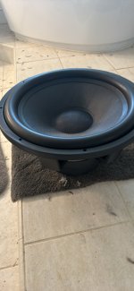
I received my Purifi PTT6.5 woofers a few days ago as part of the 
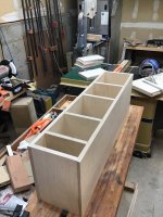
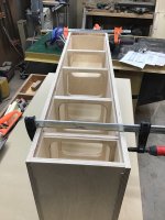
GB organized by Norman Tracy. I have been thinking about what kind of speaker to make with this special driver. I was going to use either a ribbon tweeter, or fullrange and make it into a FAST with a low crossover around 1kHz. However, I have a speaker box that has been languishing for a few years since I could never finish it. I happened to have a 0.57 cu ft cabinet that I made for an RS180P and a WG300 waveguide fitted with an RS28F dome tweeter. The cabinet also was fitted with dual 6.5in passive radiators from Dayton. As a lazy person's first test, I pulled the RS180P and dropped the PTT6.5 in and it was nearly a perfect drop-in fit. The PTT6.5 OD on the bezel was just a couple of mm smaller than the RS180P. Continuing on the lazy trend, I connected the existing XO for the RS180P and an RS28F.
845056d1589770673-exploring-purifi-woofer-speaker-builds-6100bdd6-aaf4-4470-889e-622292257e6b-jpeg


845057d1589770675-exploring-purifi-woofer-speaker-builds-d47f0fc1-3f3b-4a65-9ae1-0287c33765c7-jpeg


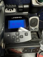
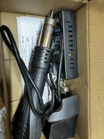
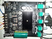
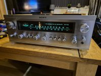
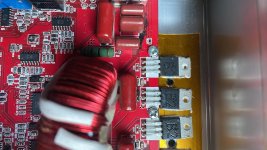
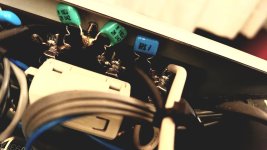
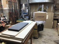
Surprisingly, it sounded very very good considering it's a totally different driver and 4ohms vs 8ohms. This got me motivated to really crank out a new speaker crossover to hear what this driver can do. So I setup my microphone (UMIK-1 calibrated by Cross Spectrum Labs), REW, and my new 
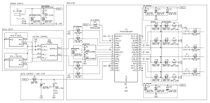
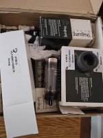
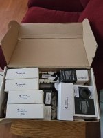
TPA3255 reference Class D amp with PFFB. Probably the only amp I have at present that can drive 4ohms (good for up to 300w+). Here is a photo of the test setup:
845667d1589957776-purifi-ptt6-5w04-01a-woofer-buy-01-ptt6-5-rs28f-harsch-xo-setup-measurement-jpg


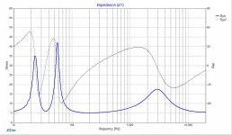
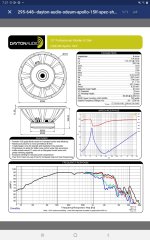
I began by measuring their T/S parameters with a DATS. Everything looked great and the values were within factory specs for Qts, fs, and SPL. Here is the DATS measurement:
845034d1589763913-purifi-ptt6-5w04-01a-woofer-buy-purifi-ptt6-5-ts-params-xrk971-jpg


The drivers were almost perfectly matched too - very unusual to have two drivers with an impedance curve that is near identical.

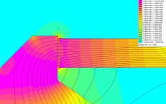
I took some frequency response FRD data with just the woofer, the tweeter, and both combined in order to figure out the acoustic center offset via acoustic interferometry to be done in Xsim. Here is a plot showing the predicted combined raw driver response with the simulated one for a 19mm offset of the tweeter relative to the woofer:
845668d1589957776-purifi-ptt6-5w04-01a-woofer-buy-03-ptt6-5-rs28f-driver-acoustic-offset-jpg


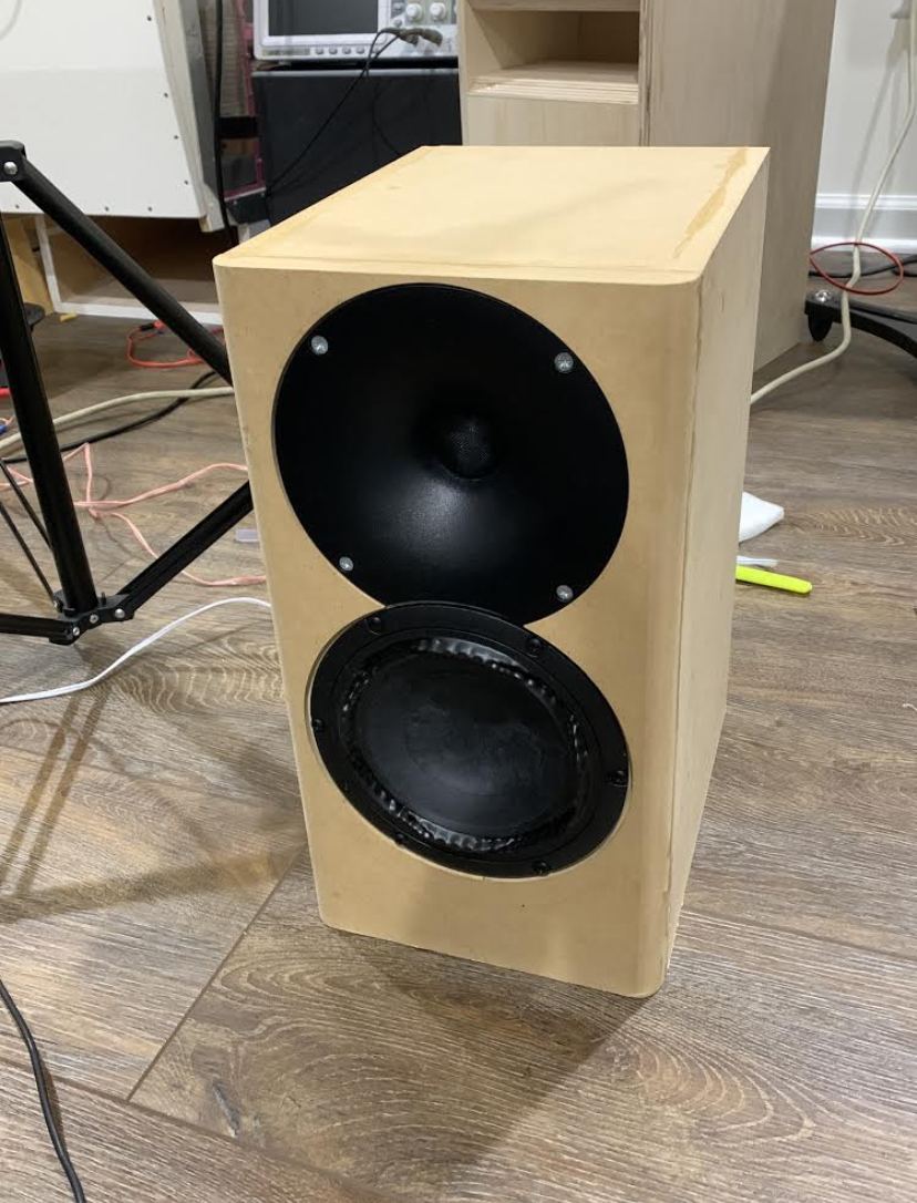
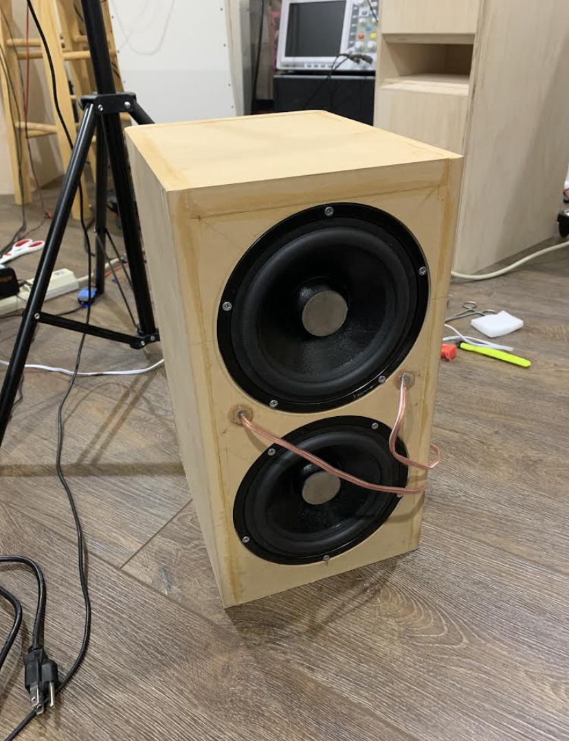
This was measured with the mic along the woofer axis (I plan to put the woofer on top and tweeter on the bottom to get a little extra time of flight delay for the tweeter while still keeping the front baffle flat), I get a 19mm offset of the tweeter and waveguide based on the interferogram match of the simulated and actual combined measurement. This is the same technique that I used on the 10F/RS225 FAST speaker in order to get time alignment. It works here even though the crossover curves are not anywhere near 1st order, but closer to what is seen on a Harsch XO with a steep 4th order low pass on the woofer and less steep 2rd order high pass on the tweeter. Furthermore, since the Purifi PTT6.5 driver has such a nice flat response out to nearly 4khz, I was able to run a high XO point of about 3.6kHz, which corresponds to a time of flight delay distance of 47.5mm (1.87in). By using the woofer as the main acoustic axis, we are able to approximately delay the tweeter by a little extra due to triangulation.

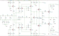
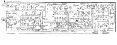
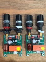
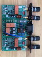
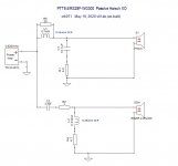
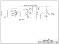
In Xsim, I modeled the following very simple crossover using only 2 inductors, 2 capacitors, and four resistors (the prototype uses multiple values from my XO development kit to build up the desired values), was able to achieve a very Harsch-like textbook XO profile. Here is the crossover schematic, as-built:
845669d1589958585-simple-passive-harsch-xo-using-ptt6-5-rs28f-waveguide-04-ptt6-5-rs28f-harsch-xo-simulation-schematic-v01ab-jpg


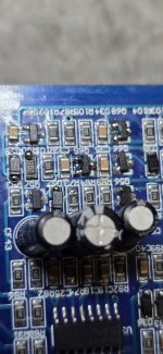
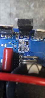
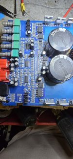
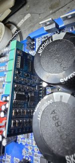
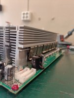
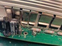
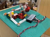
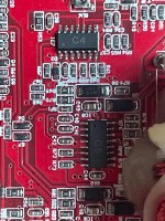
Here is a photo of the prototype crossover as implemented using my XO development kit:
845670d1589958585-simple-passive-harsch-xo-using-ptt6-5-rs28f-waveguide-05-ptt6-5-rs28f-harsch-xo-prototype-v01ab-jpg


Here is the predicted frequency response plot for this crossover:
845671d1589958585-simple-passive-harsch-xo-using-ptt6-5-rs28f-waveguide-06-ptt6-5-rs28f-harsch-xo-simulation-freq-jpg


Here is the predicted impedance plot for this crossover:
845672d1589958585-simple-passive-harsch-xo-using-ptt6-5-rs28f-waveguide-07-ptt6-5-rs28f-harsch-xo-simulation-impedance-jpg


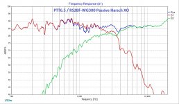
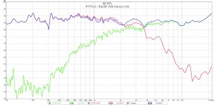
Here is the measured frequency response for 1/24th octave smoothing. Note the tell-tale dip in the system response relative to the woofer only response just to left of the crossover frequency. This is a classic sign that the Harsch XO was set up correctly.
845673d1589958585-simple-passive-harsch-xo-using-ptt6-5-rs28f-waveguide-08-ptt6-5-rs28f-wg-harsch-xo-freq-24th-octave-jpg


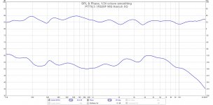
The other tell-tale sign that it is a Harsch is that there is about a 55 deg phase shift bump from the nominal, and here we see a fairly flat phase response from 100Hz to 10KHz with an approximate 55 deg rise.
845674d1589958585-simple-passive-harsch-xo-using-ptt6-5-rs28f-waveguide-09-ptt6-5-rs28f-wg-harsch-xo-phase-jpg


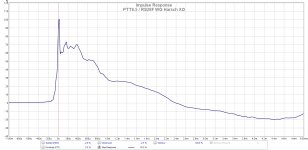
And finally, the clearest indication that this crossover is quasi transient perfect is the fact that the step response looks like a right triangle. Without this feature, the advantages of a transient perfect crossover are lost.
845675d1589958585-simple-passive-harsch-xo-using-ptt6-5-rs28f-waveguide-10-ptt6-5-rs28f-wg-harsch-xo-impulse-jpg


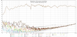
Here is the distortion associated with these measurements and although I am not using the suggested Purifi passive radiators, there is still a fairly low level of harmonic distortion.
845676d1589958582-simple-passive-harsch-xo-using-ptt6-5-rs28f-waveguide-11-ptt6-5-rs28f-wg-harsch-xo-distortion-jpg


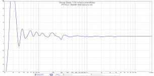
From the measurements, we can also see that the measured group delay (GD) is excellent – under 5 milliseconds down to about 45Hz.
845677d1589958585-simple-passive-harsch-xo-using-ptt6-5-rs28f-waveguide-12-ptt6-5-rs28f-wg-harsch-xo-groupdelay-jpg


Edit May 21, 2020: New Polar Data (approx angles but distance of 0.5m is correct, mic on woofer axis as designed):
845955d1590034502-simple-passive-harsch-xo-using-ptt6-5-rs28f-waveguide-ptt6-5-rs28f-woofer-axis-polar-data-0-5m-2vrms-jpg


So what we have here is sort of like the elusive missing Chalice of XO’s: a simple quasi-transient perfect higher order XO capable of rendering clean, crisp attack notes while remaining easy to implement in a flat baffle speaker with commercially available drivers and woofers. The PTT6.5 is what makes this speaker possible.
844715d1589662361-purifi-ptt6-5w04-01a-woofer-buy-d5f786c3-b586-431e-a059-0b87ca25e89e-jpeg

844716d1589662361-purifi-ptt6-5w04-01a-woofer-buy-261bdbe9-9843-413f-b76b-3639b1595645-jpeg


How does it sound? I only have it in mono, but it sounds Excellent: great balance and clarity, nice midrange weight and slam, super highs and a wide sweetspot and excellent imaging provided by the waveguide! I really am impressed by how clean it sounds, and the tweeter is working where it is mostly designed for. This leaves the woofer to handle the midbass, where it loves to operate. The bass with the dual Dayton PR’s still needs work, but this is where I think a TL is going to really do a nice job.

Here is a video of this speaker playing a song that really exercises the passive radiators. I will need to make a proper TL speaker to keep the high efficiency and low distortion bass output as these passive radiators I had were running out of xmax already.

Edit May 26, 2020: Plans for TL here
847691d159051982832-simple-passive-harsch-xo-using-ptt6-5-rs28f-waveguide-ptt6-5-tl-render-blique-v01-jpg


Waveguide adapter plate STL file here:
Simple Passive Harsch XO Using PTT6.5 and RS28F in a Waveguide

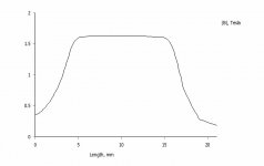
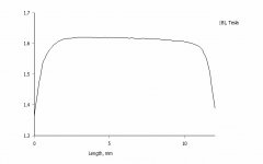
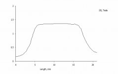
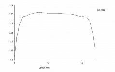
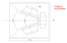
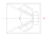
Here is response of TL predicted by Akabak, max SPL is 101dB at 21Vrms (exceeds thermal limit), and SPL at Xdamage is 104dB:
847088d1590350218-simple-passive-harsch-xo-using-ptt6-5-rs28f-waveguide-ptt6-5-tl-design-freq-1-5in-vent-2-83v-jpg


847739d1590528822-simple-passive-harsch-xo-using-ptt6-5-rs28f-waveguide-ptt6-5-tl-assembly-v01-plans-jpg


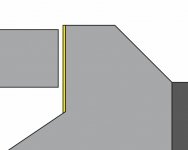
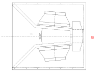
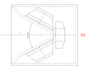
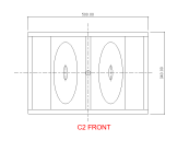
Here are the plans for just the front baffle to make a version with a removable baffle. Remember to removed the 0.75in from the front on the side view of the main plans if going this route.
Simple Passive Harsch XO Using PTT6.5 and RS28F in a Waveguide

Here are CAD files of the TL speaker (STL and STEP):
Simple Passive Harsch XO Using PTT6.5 and RS28F in a Waveguide

Final XO board with flat copper foil inductor and Jantzen and Mills resistors:
847366d1590432418-simple-passive-harsch-xo-using-ptt6-5-rs28f-waveguide-pcb-xo-speaker-02-jpg


BOM for XO here:
Simple Passive Harsch XO Using PTT6.5 and RS28F in a Waveguide

Here is measured response with new permanent XO PCB vs temporary developmental XO:
847368d1590432418-simple-passive-harsch-xo-using-ptt6-5-rs28f-waveguide-ptt6-5-rs28f-woofer-axis-pcb-xo-comapre-jpg


Edit May 29, 2020: The new RST28F-4 tweeter has been tested and verified to work with the WG300 waveguide and this speaker. Requires additional felt spaceer between the WG300 and the RST28F faceplate due to a larger grille diameter.
848429d1590773117-simple-passive-harsch-xo-using-ptt6-5-rs28f-waveguide-rst28f-vs-rs28f-wg300-compare-jpg


Edit June 14, 2020: Revised plans for the TL with corrected cutout dimensions for the drivers. This plan utilizes a removable front baffle which will simplify installation of the XO board, padding and stuffing. Moreover, it allows you to change the tweeter at a later time. The box can be flipped with the tweeter on top for a conventional LR2/LR4 crossover if desired.
Simple Passive Harsch XO Using PTT6.5 and RS28F in a Waveguide

852879d1592159336-simple-passive-harsch-xo-using-ptt6-5-rs28f-waveguide-ptt6-5-tl-v02-sheet-3-jpg


852878d1592159336-simple-passive-harsch-xo-using-ptt6-5-rs28f-waveguide-ptt6-5-tl-v02-sheet-2-jpg


EditJune 28, 2020: The completed TL speaker in BB ply for some casual listening in the kitchen:
856179d1593297126-simple-passive-harsch-xo-using-ptt6-5-rs28f-waveguide-cf790e3c-21c3-4918-bb37-81eac893bc89-jpeg


Edit June 29, 2020: Here is the schematic showing the final parts used as shown in the photo of the XO and measurements above:
856668d1593469641-simple-passive-harsch-xo-using-ptt6-5-rs28f-waveguide-ptt6-5-rs28f-wg300-xo-v02-schematic-final-jpg


Edit Aug. 15, 2020: New revised XO for better tonal balance - more info here:
868139d1597513796-simple-passive-harsch-xo-using-ptt6-5-rs28f-waveguide-ptt6-5-rs28f-wg300-xo-schematic-jpg


F3 of 39Hz and slight downward tilt in the response:
868142d1597513796-simple-passive-harsch-xo-using-ptt6-5-rs28f-waveguide-ptt6-5-rs28f-wg300-tl-xo-freq-2vrms-0-5m-jpg


Final XO using Dayton Precision 1% 10W resistors, Jantzen 2.5mH 18ga coil, Dayton 0.5mH 20ga coil, Audyn Q2 22uF MKP for woofer and Dayton Precision 2.2uF MKP 250v 1% for the tweeter. I have a bypass of 0.1uF MKP Dayton as a place holder for a Miflex 0.1uF 600v bypass on the other channel.
869222d1597958531-simple-passive-harsch-xo-using-ptt6-5-rs28f-waveguide-ptt6-5-rs28f-wg300-xo-build-ch2-jpg


Here is the channel with the Miflex, I will see if I can do an AB in mono one of these days:
869067d1597875523-simple-passive-harsch-xo-using-ptt6-5-rs28f-waveguide-ptt6-5-rs28f-wg300-xo-miflex-dayton-resistors-jpg


Edit Mar 23, 2021: I have developed a floorstanding TL. More info here.
attachment.php

Attachments

  • 04-PTT6.5-RS28F-Harsch-XO-Simulation-Schematic-v01ab.jpg
    04-PTT6.5-RS28F-Harsch-XO-Simulation-Schematic-v01ab.jpg
    56.2 KB · Views: 12,187
  • 05-PTT6.5-RS28F-Harsch-XO-Prototype-v01ab.jpg
    05-PTT6.5-RS28F-Harsch-XO-Prototype-v01ab.jpg
    506.8 KB · Views: 11,531
  • 06-PTT6.5-RS28F-Harsch-XO-Simulation-Freq.jpg
    06-PTT6.5-RS28F-Harsch-XO-Simulation-Freq.jpg
    167.5 KB · Views: 11,591
  • 07-PTT6.5-RS28F-Harsch-XO-Simulation-Impedance.jpg
    07-PTT6.5-RS28F-Harsch-XO-Simulation-Impedance.jpg
    172.6 KB · Views: 8,388
  • 08-PTT6.5-RS28F-WG-Harsch-XO-Freq-24th-octave.jpg
    08-PTT6.5-RS28F-WG-Harsch-XO-Freq-24th-octave.jpg
    211.7 KB · Views: 10,949
  • 09-PTT6.5-RS28F-WG-Harsch-XO-Phase.jpg
    09-PTT6.5-RS28F-WG-Harsch-XO-Phase.jpg
    175.5 KB · Views: 10,636
  • 10-PTT6.5-RS28F-WG-Harsch-XO-Impulse.jpg
    10-PTT6.5-RS28F-WG-Harsch-XO-Impulse.jpg
    186.1 KB · Views: 12,200
  • 11-PTT6.5-RS28F-WG-Harsch-XO-Distortion.jpg
    11-PTT6.5-RS28F-WG-Harsch-XO-Distortion.jpg
    299.8 KB · Views: 7,952
  • 12-PTT6.5-RS28F-WG-Harsch-XO-GroupDelay.jpg
    12-PTT6.5-RS28F-WG-Harsch-XO-GroupDelay.jpg
    154.5 KB · Views: 8,072

Repurpose bricked Marantz SA-14?

So, I picked this unit up for next to nothing years ago. Unfortunately, the SACD module is effectively bricked due to it being a first generation version; it will no longer read discs, unless the firmware is updated. In a vain attempt, I did swap laser modules, but it behaves the same way. Spins up, tries to read a disc, the servos sound like mix master mike, then gives up after a few attempts.

Unless someone here has reverse engineered the flashing jig and happens to have the proper ROM file laying around, I want to see what else I can do with this piece. It's a real shame otherwise. Nicely built unit!

I was thinking maybe it could be turned into a USB or optical DAC? Has this already been done? Other ideas...

TIE Brute: open-baffle / horn speakers

Hi, guys. I have been reading DIYaudio for many years and received a lot of useful information and inspiration. For the first time, I decided to write. Sorry for the possible mistakes, my English is not always good.

I want to present my system. It's still in progress, but it's already bringing me a lot of fun and music.
aaf90e3b29da9a714e519d8ea771ab7521330572_2_1380x766.jpeg


Speakes inspired by Reflector audio. I call them TIE Brute, they look like heavy starfighter from Starwars 🙂 All information about the drivers is shown in the picture. As you might guess, an open-baffle + driver in CD horn.

cdc51716c3127e510a52a07f0e36cf2bfbb853f0.jpeg

c47302ab9284890f2693152515466b95ba6e8561.jpeg

0279e88c696143f765371c0b1cd8a67023cf9d37.jpeg


After a long period of experiments, I came up with an extremely simple crossover. In short: the Faitals are filtered acoustically by turning out, the compression driver with a 4.7 capacitor gives a shelf response, and then I use digital or analog equalization to the desired frequency response.

This may look not-so-smart and too funky-punky, but it works surprisingly well!

(I didn't save any good measurements, only such shitty ones with all sorts of reflections, in reality, there is no failure at 500 Hz, mic position. But hope, the idea will be clear, and if it is necessary, I can make normal measurements. Funky-punky as I say))).

923991879_2021-04-2210_18_03.thumb.jpg.84c257c78746dc001825e0f29f1cd2b2.jpg

67980608_2021-04-2210_18_11.thumb.jpg.8cd08e93d89f19ec81b98e5deb52e897.jpg


At low end 2x 10-inch subwoofers with the added servo (piezo sensor on the driver and feedback board in front of the amplifier). They can not be heard until you turn them off 🙂

And a small video presentation on the phone, of course, the live sound is better, it's just for fun:

Demo - YouTube
  • Like
Reactions: ianbo

Need help with Giesberts HEXFET AMP

Hi everyone! 😎

I have a project with this amp, i was nearly done with it, but then this problem came out! :bawling:

So i made everything ready and started to test the amp... Everything was fine until i put FETs fuses to the holders and bang.. every IRF9540N and IRF540N shorted and every fuse blew. Then I thought that the problem was gate voltage so I removed the wrecked fets and put multimeter over R24 and R27. I adjusted voltage as low as it´s possible, 2,8V in my amp.

I soldered a new fets in their places and put only 400mA source fuses in holders. Then I turned the amp on. Everything seemed to be under control, so I adjusted gate to source current to 200mA. It was very steady and thought that everything worked fine.

So i shut it down and put the normal 2.5A fuses back to their holders and turned the amp on again. BANG! every fuse blew and the fets were gone.

So I came here to look if someone else have samekind of problems with that amp. I found that someone here have the amp which is working and some have the same problem with their IGBT version.

I don´t have every value of the components just right because couldn´t find those and thought that those would work fine. Powersupply is 100% same as in original. Here is the values that I have used to countervail some components on the apmlifier PCB.

T12 IRF9540N (original IRF9540)
T13 IRF540N (original IRF540)

R6 82.0 ohm 2% (original 84.5 ohm 1%)

C3, C4 2.2nF 63V (original 2.7nF)
C5 470pF styroflex (original 330pF styroflex)
C9 1uF MKS4 100V (original 1uF polypropylene)

Ok I know that C5 should be really close that 330pF but can´t get a right component yet. And isn´t it just affect to maximum frequency of the amp. (so 470pF should decrease the maximum frequency?)

🙄

So if you guys could help me out of this situation i would appreciate that very much! 🙂

I put links to the schematics here:

http://www.mif.pg.gda.pl/homepages/tom/files/120MOS.gif

http://www.arky.ru/audio/shem/igbt/Sch_delay.gif

http://www.arky.ru/audio/shem/igbt/wiring.gif

http://www.arky.ru/audio/shem/igbt/Sch_supply.gif

Direct drive ribbon amp power requirement?

I'm looking to build a current source amp to direct drive ribbons. I have scanned all of the previous threads from over the years on the topic and haven't found the info I'm looking for.

I want the amp to be powerful enough to drive theoretical "Full range" ribbon speakers. I.E. very big ribbons.
I am pulling my hair out trying to find out how much power I need, I have no clue how power translates into SPL for ribbons and I can't seem to find the answer anywhere.
I can't begin to design such an amp without knowing the required power output.
I have a few design thoughts in my head but I first need the answer to my above question.

Can anyone help me out?

Elektor's "Ulti Amp"

Has anybody tried what at least in the German issue was called the "Ulti Amp"? It was published in 5/95. Measured specs were more than excellent, but I'm interested if anyone can comment on the sound.

The dual transistors used in the two gain stages (2N2914, BFX36) have long been obsolete anyway. I've always wanted to build one (some parts are still in my junkbox), but never proceded as I came across other concepts (current feedback, class A) I found more interesting.

The protection circuit is somewhat special (it shorts the PSU rails via Triacs instead of opening a speaker relay) and can easily be adopted for use in any amplifier.

About circuit design optimization _ a general question

Good morning to Everyone
I immediately apologize for a reasoning that probably will sound inconclusive
I recently discovered the LTSpice program but I couldn't get decent THD vsHz graphs
With the very kind and precious help of Mr Mooly who provided me with the most appropriate settings I began to see some THD graphs and I fell in love with them
I started playing with voltages and values and types of transistors in the most banal circuits in order to reach a lower THD and I saw that the result changes considerably from total non-functioning to rather interesting results.
Now the question that's on my mind.
Looking at the most popular discussions here in the forum I think I'm quite isolated in my curiosity to see the limits of simpler circuits (i.e. low parts count)
I guess that simpler topologies must have intrinsic limits and this makes them not interesting for who wants to reach the very best measurements.
But what are their real limits?
I mean there are a lot of variables already in a simple circuit from the type of parts and values and supply voltages etc.
If optimizing a simple circuit already appears so challenging and demanding what would be optimizing a very complex one (i.e. with many many parts)?
I have seen a discrete opamp with 80 passive and active parts 😵
The number of variables increases dramatically at a level that is pratically impossible to manage.
I have the feeling that people are more challenged about doing something complex than getting the most out of something simple.
like those chefs who don't care about the quality of the raw materials but add tons of different sauces to their recipes that only confuse the sense of taste
Maybe it's my impression
On another hand I was also struck by a review of a preamp some time ago
The reviewer, clearly an electronics expert, believed the circuit quite a bit. In fact, he saw some even trivial flaws in it
Yet that circuit tested on the bench still gave truly remarkable measurements in terms of THD+noise
His explanation was that the results were achieved with an optimization of a circuit that on the paper looks quite simple.
What is your approach on the subject ?
And moreover how do you optimize your designs ?
  • Thank You
Reactions: cumbb

Miro AD1865 DAC

Sold

Spare set of Miro AD1865 DAC for sale. i2s inputs on board.
Circuit design and board info available here:
https://www.diyaudio.com/community/...2s-input-nos-r-2r.354078/page-72#post-6525201
You need a PSU to supply +/-5V and +5V and I2s source for this DAC to function.
A pair of OPA1655 will be supplied for the IV stage. Many members feel that this op amp gives very good and satisfying sound as a simple onboard op amp IV.
However, I recommend that you supply separate +/-12V for the op amps. This can be done easily by breaking jumpers J10, J11, J12 and J13 and feed your psu to the jumper pads.

Price is $100USD, and it covers the registered shipping worldwide from Singapore.

My preferred transaction would be PAYPAL FF.
  • Like
Reactions: Brijac

WTB Chinese Dual AKM DAC Board

Hello there, i'm wondering if anyone on here has a chinese dual chip AKM dac board with the LCD and controller (either buttons or rotary) from a past or abandoned project. My board is a dual AKM 4490 board (as pictured), but I think the controller is bad. I'd be happy to buy a complete second hand board or just the parts depending on what people have. I understand from reading the forums here that the controllers work across multiple boards with AK4399/4490/4495 and 4497 chips. I know a lot of people were experimenting with these boards a few years ago, so maybe someone has one lying around they might be willing to sell. Thanks in advance!

Multiple I2S sources

Hello

I was designing my first amp and ran in some issues.
My intended block diagram - ADC->Raspberry Pi->amp module with its own DAC
I want to supply the amp module with I2S signal so it doesn't get converted multiple time and lose some quality so RPi in this case must be I2S master.
I also want to add AUX in with ADC so that creates another I2S master source.
Problem with this is that RPi only has one I2S codec so it can communicate with one line (2 channel) I2S.

My question is how to make this thing work.
So far from what I have read I believe that using some kind of analog switch IC or multiplexer would be the way to go with one slight drawback of having a click on switch.
What could be other solutions that I missed out on or how to eliminate the click (syncing master clock of two masters??).

Some other things I came up with: HDMI-I2S converter for extra output, WM8960 I2S codec (but it wouldn't output I2S OR it wouldn't take it as an input so only one way also like RPi itself)

Mid/Hi design reduction inspired by Martin Philshave

Hi Folks,

Iv been wanting to build some mid/hi tops to go with my tham15's.

I used to have some martin philshaves and loved them. I cant deal with the complexity of synergy horns, so I thought Id attempt a "philshave minimal reduction", that would:

  • be simple to build
  • sit neatly on top of my tham15's.
  • use lower cost drivers
  • hopefully have some projection and imaging
  • use one sheet of plywood for a pair.
  • not have to custom build phase plugs or custom throat adapter.

I dont know anything about hornresp, so the iterations attached below may be nonsense. But Im hoping for any feedback, comments, guidance on moving this design to a good sounding and simple build.

PS unsure if the drivers should be fully open on the front, or if they should have a band pass port like sysnergys?

Attachments

  • A.png
    A.png
    8.3 KB · Views: 321
  • B.png
    B.png
    4.9 KB · Views: 134
  • C1.png
    C1.png
    6.1 KB · Views: 133
  • C2.png
    C2.png
    6.2 KB · Views: 136
  • C2 FRONT.png
    C2 FRONT.png
    4.3 KB · Views: 172
  • martin mh212 planview.gif
    martin mh212 planview.gif
    127.5 KB · Views: 251

Polar Plot Python Script

This thread is a spin off from the now closed "Turntable Speed Stability" thread. Scott Wurcer had posted a Python script that read a .wav file of a 3150Hz test LP tone and plotted 2 revs on a polar plot to display W&F. I've since taken the script and made a number of additions to it:

1. Make all of the parameters user selectable from the command line.
2. Added an optional 3rd plot for a reference line at a user selected frequency.
3. Added a direct W&F measurement (2-Sigma method) and display the results on the plot.
4. Created a simple Visual Basic app that allows the user to load the .wav file and set the parameters.
5. A "rotate" parameter to realign the output with previous plots to make comparisons easier.

Polar Plot.jpg


I wasn't able to get the VB app to work with newer versions of Python because of the Anaconda prompt, but it works fine on v2.0 and older.

Below is a plot I made from a prototype direct drive turntable taken directly from the optical encoder attached to the platter. The Hz/Tick value is 1Hz where the normal resolution on Scott's version was 3Hz, so it is 3x more sensitive.

The modified .py file is attached (file extension is changed to .txt). Hats off to Scott Wurcer for the original script.

To run this from the command line, type: C:\>Python polarplotVB.py [wavefile.wav] [filter freq] [Secs/Rev] [Hz/Tick] [center freq] [rotate deg]

For the above example: C:\>Python polarplotVB.py "LSI75 24-Oct-23.wav" 45 1.8 1.0 3125 0 {extra spaces added for clarity}

The quotes are needed around the .wav file because it has a space in the name; the quotes prevent the command prompt from interpreting the name as 2 separate parameters.


LSI75 24-Oct-23.png

Attachments

  • Like
Reactions: ralphfcooke

Large Desktop Full Range with Tweeter

I had a soundbar for my computer audio and I finally got fed up with it. Half a need for better sound and half to acquire more speaker design knowledge, I made these. I used basic math only to calculate it's size and shape, its roughly .18 cubic feet with a 3 1/2 inch full range and a 90w piezo tweeter. I went with the Piezo because I wanted to make the design without a crossover. The piezo's work nicely, but they definitely introduce listener fatigue fairly quickly

I'm still breaking in the BMR's so I can fully comment on the sound, but so far I'm impressed. Please ignore the block of wood adding the tilt, it's temporary. This was made out of convince, that is the parts were all part of past projects. I would love to hear design critiques, no matter how harsh they may be.... I'm here to learn.

image_123650291.JPG


These measurements are for a general idea of the speakers capabilities, I used REW but with an uncalibrated mic
Screen Shot 2024-08-14 at 8.45.18 PM.png
  • Like
Reactions: stv

Marshall DSL40CR farting

I have one of these amps to fix for a customer. The complaint was it sounded like water gurgling thru the peaker. It is basically a low freq rumble, like a wavy lp. I determined it is past the preamp section. Even with all knobs on zero.

I tried different tubes and the same thing. I checked the bias currents, and for the high power setting it is ight at 33 mA. There is a low power setting, part of the Standby switch, they swith the B+ to 150v. The C version they had a Pentode/Triode switch that changed the screen grd voltage only to 150. But the CR version they appear switch the voltage to the transformer center tap, and the screen resistors to 150v. They also change the bias voltage and increase the bias current to about 85mA. But with the plate voltage at 1/3 the normal value, you can have 3x the bias current and the tube is at the same power dissipation.

I guess that is a clever way to make sure you get tube breakup even at the low power setting? Clever guys there at Marshall.

I ound some talk on the Marshall forum tht these amps had this issue when first released. They said there it was linked to internal cable routing too near the reverb effects board inside. I will try contacting Marshall, but they usually just say take it to an authorized service center. They don’t mind fessing to them, but the general public doesn’t have a need to know.

I was just wonderig if anybody has seen or heard this kind of issue, and what the cuse was. The only time I heard something like it, was a power tube issue. I tried different tubes already with no help.

Recommend a USB soundcard for making FRD files?

Greetings all,
I built my speakers and the next step is measuring them so I can design a crossover.
I currently have:
  • A Dayton Audio calibrated microphone and Phantom power supply
  • A Dayton Audio DATS V3 for the ZMA files.
  • An amplifier (of course)
  • A laptop with a mono microphone which (I believe) can not play and record simultaneously.
  • I intend to use ARTA.
So I need an external sound card. There are so many to choose from! Most are 5+ channels and most don't have the XLR input needed for the microphone. The amplifier takes unbalanced/RCA inputs. I don't know what to look for in a soundcard. What specs are important? I also don't want to spend more than . . . say . . . $100.

I'm hoping someone on this forum could just tell me what they are using, or would recommend.

Thanks in advance!

Sometimes it pays to read the instructions

A couple of days ago, I saw a video online titled "We've all been doing drywall wrong". In the beginning, the host repeats the title and then zooms in on a bucket of drywall compound. Focusing on the sanding part of the instructions. The first item recommended for sanding is a wet sponge. Wait, what? If you're like me, you never read the instructions on a bucket of drywall compound. You learned from watching other people. You apply the compound, let it dry and then using a sanding screen or block. And it makes a hell of the mess. Fine drywall particles is nasty stuff to breath in. And no matter what goggles and mask I wear, it always seems to find its way in my eyes and nose. Well, I've been using a wet sponge for the last two days at work and I feel this should be shouted from the mountaintops. The wet sponge softens and smooths the drywall rather than just kicking it up as dust. No need for a mask or goggles or cleaning dust off every surface in the vicinity. Yeah, maybe I should have read the instructions.

Subwoofer options with LG driver, measured impedance and TS params

Hello there!

I need a sub for a small living room. Asking about recommended enclosure config, I have two possible ones to get started with.

Are those reasonable setups?
What would you pick?

-----

I got this driver from a wireless sub that came with a LG soundbar. I didn't use it much. It seems there are a few different drivers labeled LGZ40. It came in a ≈ 9L ported enclosure.

1705982834591.png1705982787582.png

I measured this (attached full file).

fs 71.1 Hz
Re 3.51 ohm
Qms 7.663 Qes 1.118 Qts 0.976
Mms 37.23 g Cms 0.134 mm/N Rms 2.171 kg/s
Vas 3.91 litres Bl 7.223 Tm
Lp (1W/1m) 83.05 dB
Dd 13.50 cm Sd 143.1 cm^2

1705984229245.png


I see two configurations that look interesting.

1) Ported @ 30Hz in a 18L box. 10W.

1705983634470.png
1705983662330.png


2) 4th order. 10w.

1705983888305.png
1705983914850.png
1705983926854.png


Thanks.

Attachments

Quick question about a speaker I recently made

Hi, just basically trying to figure out the cause of an issue that has been mentioned about an MTM I made recently. After doing multiple measurements of the speaker with the omnimic, and countless hours of listening, I gave the speaker to a friend to get their opinion on it. All of my checks and tests seemed good to me, but he came back to me saying that 'although the speaker is ridiculously clear and detailed' he finds it slightly 'boring', he feels that it has no punch and is missing something. Now the FR is flat to within 2db, the box is MDF clad in copper making it extremely solid, it feels like knocking on concrete, and the crossover has good quality parts and wire, so what could be the cause of his disappointment in it? It has a built in bluetooth amp (mono) which sounds good to my ears, and everyone else who has heard that model of speaker has loved it too, so I wonder, is it likely,

He's used to a lot of off the shelf speakers (he has a bose BT speaker atm) that exaggerate bass and treble in their crossovers? And so hearing an accurate speaker now seems lacking to him?

There's maybe EQ on his phone that is affecting the speakers response?

Box or port maybe too small and he's good at hearing that in the music, better than me?

Or should I have given the FR a more smiley face shape rather than flat to make it sound more exciting?

I really don't know, I realise your missing a lot of information here but I'm just trying to get a few ideas on things that I can check for when he returns the speaker, basically things that in general could cause a speaker to sound lacking in excitement even with the good quality xover parts and solid enclosure, any ideas would be appreciated as I really don't enjoy the feeling of disappointing someone. Thanks

Anyone explain what these small capacitors are doing on the output of an amplifier?

Hi.
Opened my Denon PMA1600NE last week, I saw 2 small capacitors between the output binding posts, 2 x 1100pF (green 112J) between each speaker output terminal and case chassis, there is also 1 x 332J (3300pF blue) between positive speaker terminal and earth on each output.
Anyone know why these are there? I do not see these on my other 2 amplifiers.

Lastly, when looking at my speaker crossover, I noticed a small inductor (in series) on the end tweeter circuit before the + wire to the speaker. The inductor comes after the series capacitors and padding resistor and is in series (last component) before leaving the board to the tweeter, Never seen that before, the Speaker is Elac ubr ref.

Thanks in advance.

Attachments

  • 20240303_041017.jpg
    20240303_041017.jpg
    267.2 KB · Views: 162

XT30 high current connectors: good or not?

For a while these DC connectors have become popular. Understandable as they can be connected fast and one can not make mistakes as with connector blocks. They are specified for 500V DC maximum, 15A of current and 1000 matings. Now Phoenix connector blocks have never disappointed me when used right but these have a certain attraction. Small, handy, fast, cheap but the main parameter "reliability" is unknown.

Do you know these and what do you think of them? I see them in battery fed throw away toys but also in university developed hardware. They start to show up on Aliexpress/Taobao audio electronics. Please note that they are gold plated which is unusual in normal industry quality high current connectors. Could be a hint that again a metallurgy knowledge mistake was made which is not unusual. They seem cheap Chinese stuff only popular because of low cost and the wish to only use locally produced stuff but they might be really good. The information found online is somewhat suspect and of YouTube quality (clicks for opinionated data). I attached the datasheet. Also: which crimping tool is needed?

https://www.ebay.de/itm/40503493934...MI9dLa3PH4hwMVTqeDBx3nEA-VEAQYCiABEgL5BvD_BwE

Attachments

  • s-l960.jpg
    s-l960.jpg
    45.3 KB · Views: 77
  • XT30U-M.pdf
    XT30U-M.pdf
    2.6 MB · Views: 63

Help finding a correct value full wave bridge

The bridge rectifiers that came with the system are BR860A. They are no longer available. Supposably HVPFR6 are the subs they say should work. Over a few months of operating, the HVPFR6 blows and shorts closed. Anybody have any advice on a better Bridge that can handle these voltages. F101 and F102 are 5amp slow blow.

Attachments

  • Flasher.jpg
    Flasher.jpg
    147.1 KB · Views: 114

Zero Knowledge but eager to learn

Hi Folks,

Although I have soldered well over a hundred boards in my life (and got them all to work) I am totally clueless when it comes down to electronics design or how any of those boards actually work. As a result I have a hard time understanding a lot of the stuff in various threads here. But I can put components and modules together and make stuff work (eventually).

Hoping to learn and build a better, custom system and get better sound without breaking the bank.

Mike aka ZK

Anyone use these new Dayton drivers?

I recently started a project for some slightly upscale extended range "subs" for my son's studio, originally having chosen the JBL 2268HPL in a large vented cab. We needed some extended range up into the 200 hz area with low THD and this JBL looked good. Unfortunately it looks like it won't go that low using an unassisted vented tuning, originally trying to get down into the very low 30s to upper 20s hz cutoff without greatly exceeding xmax. So now we had to regroup and look for a 15 or dual 12S with good midbass, sensitivity, low distortion and minimal time domain issues.

These new Dayton woofers look promising, although having a lower Qts. Their other specs look great. I'm weary of their build quality and distortion figures up into the lower 100s hz area. Has any had experience with these drivers?

Attachments

  • Screenshot_20240813-072204_PDF Reader PRO.jpg
    Screenshot_20240813-072204_PDF Reader PRO.jpg
    365.5 KB · Views: 327
  • Screenshot_20240813-072110_PDF Reader PRO.jpg
    Screenshot_20240813-072110_PDF Reader PRO.jpg
    364.4 KB · Views: 332

Troels Gravesen Ekta-7741 Speaker Build

I thought I would post my experience building Troels Gravesen’s Ekta-7741 speakers and hopefully provide learnings that might prove helpful to other DIYers.

The hardest part was choosing which TG speaker kit to build since there are many options but little understanding of how they sound. I’ve been looking at TG’s website for a number of years now, mostly for inspiration. The only decision criteria I could come up with was to review the kit drivers selection for design intent and chat with people who have built the speakers I’m interested in.

The two finalists were the Revelator-851 and Ekta-7741. On paper, they both improve on what my Sonus Faber Auditor M’s do. Two people who have built several TG designs, including the 851’s, recommended the 851’s. A third person recommended the Ekta-7741 over the Etka MarkII having built both. For me, it came down to a choice between the deeper bass of the 851’s versus the promise of improved midrange clarity and directivity of the 7741. Having heard neither, I chose the 7741 which also happens to have a simpler crossover topology.
http://www.troelsgravesen.dk/Ekta-7741.htm

Others in my position would have just bought a couple subwoofers to go with my SF’s for a little less money and a lot less effort and called it good. That notion crossed my mind but that’s not me. If you’re reading this, it’s probably not you either.

I’m not sure these types of projects are full-on DIY since the engineering has all been done by someone else. I consider this more of a shop project. I build a lot of furniture and have a fairly complete woodworking shop although not a lot of space. The only tools I bought for this project have been a small circle compass for routing the driver holes and some special router bits.

Here is what I have so far.

Attachments

  • IMG_1181.jpg
    IMG_1181.jpg
    307.7 KB · Views: 320
  • IMG_1188.jpg
    IMG_1188.jpg
    311 KB · Views: 312
  • IMG_1190.jpg
    IMG_1190.jpg
    264.7 KB · Views: 314

New Old Guy Saying Hello

Hi everyone, Just a note to say hello and confess that I know way less than I thought I did 🙂.
Music was always a passion and since I couldn't play an instrument if my life depended on it, I started
building my own speakers in the 70's. I moved on to building and repairing them through the 80's to make a
sub standard living but it was enough to keep me in beer and music! Needless to say I got married and the
loud systems went the way of the dodo. Lately I had this urge to start messing with cheap tube stuff. As a young guy
I had very little patience for it but I find my tastes have changed. I look forward to sharing what little I know and hanging
out a bit

Ron

Here because you know

Hi. I know very little about DIY Audio but would like to pose a few questions to those that know. I have a very modest 2 speaker system comprising a few more recent amplifiers which take turns, a lowly Chromecast Audio which I had for years and a pair of 30 year old Mission 752 Freedom's. These replaced some Stirling BBC Reference LS3/6's and prior to that active KEF LS50 Wireless 2 and, before that, B&W Formation Duo's. Quite some change and I just did not get on with the two Actives. The Stirling also never engaged (possibly an amplification issue) and the Missions were a lucky find, I did not know much about them prior. I actually travelled up to London to pick them up (from the South Coast). The gentlemen selling them had another pair which he kept and he wanted these to go to a good home. The amplifiers currently in use are my trusty Arcam SA20, a Cyrus ONE Cast and an Audiolab 6000A. All commercial products, easily available and not in any way special other than I like each one for different reasons. I sold a Hegel H95 as I did not really liked it and I also let go of my Rega P3 as I moved forwards and backwards between Spain and the UK (Hifi was in storage during this time). My headphone stuff includes a Mojo2, FiiO K11, Hifiman, Beyerdynamic, Sennheiser, Meze and Grado headphones. Just random stuff that gives me pleasure. Some photos, older and newer about some of my Hifi. Thank you.

https://i.postimg.cc/0yJZ2g0P/20221109_140636-01.jpg

https://i.postimg.cc/pTTkjrNy/20230121_131622.jpg

https://i.postimg.cc/T1JYxtpv/20230210_213956-01.jpg

https://i.postimg.cc/2yYJ5QSR/20230127_193655-02.jpg

https://i.postimg.cc/G2xzbmdh/20220325_112743-01.jpg

https://i.postimg.cc/R0JyGXgw/20220325_112007-01.jpg

https://i.postimg.cc/zB8S2YKm/IMG_20210712_142458.jpg

https://i.postimg.cc/k5DqLRsN/1000012014-01.jpg

https://i.postimg.cc/k4455x3w/20230918-150953.jpg

https://i.postimg.cc/GmNwtNXp/IMG-1643.jpg

https://i.postimg.cc/Dwf2Xfx8/20231223_112750.jpg

https://i.postimg.cc/YS9H51Mk/20230503_211023.jpg

https://i.postimg.cc/2yYJ5QSR/20230127_193655-02.jpg

Seeking Advice on Speaker Selection and Enclosure Design for Smart Home Device (Sense360)

Hi everyone,

I’m currently working on a smart home project called Sense360 and could use some expert advice on selecting the right speaker and designing the optimal enclosure. The device is intended to serve both as a voice assistant and a music playback unit, so I’m aiming for a balance between clear voice reproduction and decent audio quality for music.

What I Need Help With:

1. Speaker Selection:
• Requirements: I’m looking for a full-range speaker that can handle voice commands clearly while still delivering good-quality music playback.
• Power Handling: Around 20-25W RMS.
• Size Constraints: Ideally 2” to 3.5” drivers that fit within a compact enclosure.
• Brands/Models: Any recommendations for specific brands or models that you’ve had good experiences with?
2. Enclosure Design:
• Type: What type of enclosure (sealed, ported, etc.) would you recommend for a balanced sound that complements both voice and music playback?
• Placement: Tips on speaker placement within the enclosure for optimal performance. Should the speaker be front-firing, down-firing, or another configuration?
• Material: What materials and thicknesses work best for minimizing resonance and improving sound quality?
3. General Advice:
• Integration: Any advice on integrating the speaker with other components (like microphones for the voice assistant) to avoid interference or feedback?
• Crossover: Should I consider using a crossover or additional components to optimize sound performance?

I appreciate any insights you can share on making Sense360 a device that offers both excellent voice recognition and enjoyable music playback. Looking forward to your suggestions!

Thanks in advance,
Projects by fanatics, for fanatics
Get answers and advice for everyone wanting to learn the art of audio.
Join the Community
507,572
Members
7,877,493
Messages

Filter

Forum Statistics

Threads
405,749
Messages
7,877,493
Members
507,572
Latest member
NakajimaYusuke