Phono selector

Hello. I have a adcom preamp with only a single phono input. I have tube amps and decent speakers. I got an Alexandra 2 and also a homebuilt DIY table. I’d love to have a phono source selector to switch between the two but hear about noise introduced by sloppy switches. Any suggestions for an input or should I get a tube phono preamp? Recommendations.
Thanks.

Newbie safety 101

Hi,

So I've ordered a few bits to start tinkering with DIY speakers and CamillaDSP (RPi5 & HiFiBerry DAC8x):

4 x Wavcor WF168WA02
2 x Vifa NE25VTS-04 tweeter)
3 x TPA3255 boards -- (https://www.aliexpress.com/item/1005006640455408.html)

I'm pretty unsure about proper tinkering "safety", basically how to avoid destroying things.

I'm not planning passive crossovers. I'm going to use an amp channel for every driver.

I gather I should use a 'protection cap' on the tweeters.

I'm going to run the TPA3255 boards from a 24v SMPS dialed back a few volts that should severely limit the watts going to the drivers. I was thinking one TPA3255 board for one L & R driver so one TPA3255 board to run the tweeters. I want each woofer to have it's own amp channel so that I can try a 2.5-way crossover.

So the question is what additional precautions should I use while testing?

Thanks
Richard

voltage differences

Hi, I have a technical question, hopefully someone can enlighten me.... I am from USA, which uses 120V 60Hz power sources. If I buy an AV or an amplifier from Japan, which uses 100V 50Hz, and import to the US:
1. WITHOUT THE POWER CONVERTER (Step up/down..etc..), will the Japanese's unit (which uses 100V-50Hz) be working properly?
2. Assumed it works, will the differences in the electrical current affect/change the sound quality, performance of the receiver/amp?
3. Will the different in electrical current affect the longevity of the unit?

4. Can I buy the power supply from the US version unit, and replace the japanse's power supply.... will that fix all the issues? or will there be more to it (tuning inside the circuitry...etc). I am aware the radio frequencies will be different, but I am not using the radio. Thanks

Need source for AVR’s memory capacitor

Harman Kardon AVR 110. Picked up for $10. Has common issue of memory capacitor failure. I’d like to spend as little as possible, shipped to Georgia, USA. Any recommendations? I’m not in a rush so slow shipping is fine. Do I need an “exact” replacement? I wish I could put any old cap in there. Thanks!

PS- leads look short because they broke off as I bent it vertical. They broke off in the middle of the leads, not at the board.

Attachments

  • IMG_3401.jpeg
    IMG_3401.jpeg
    411.8 KB · Views: 91
  • IMG_3398.jpeg
    IMG_3398.jpeg
    306.5 KB · Views: 106
  • IMG_3399.jpeg
    IMG_3399.jpeg
    325.7 KB · Views: 87
  • IMG_3400.jpeg
    IMG_3400.jpeg
    327.5 KB · Views: 82

WTB complete solid state stereo amp or SS / tube preamp you've built

I'd like to buy someone's solid state amplifier, CONUS, preferably class AB, or a SS or tube preamp. I'm redoing my system and no time / energy to build something myself. And, frankly, commercial stuff just doesn't impress me much anymore on performance relative to cost

Let me know what you have with $ and pictures, again CONUS only

Newbie

Greetings from the far reaches of Rhode Island. No, it's not even an island!

I first fell in love with soldering in the late 1960s building a Heathkit stereo receiver. That was followed by several other Heathkit projects. I have done several re-caps of old music equipment, and am currently rejuvenating a McIntosh C22 (very first model). I recently build a Moog Model D clone (with SMDs, no less!) and am about to start its final testing and calibration. I got 2/3 the way through building a 176 compressor from Drip Electronics, but that is paused indefinitely until the designer/owner of Drip follows through with answering questions -- a topic for another day :-(

I just successfully upgraded the power supply on my trusty Linn LP12 and I am about to re-cap and calibrate two Hickok 752A tube testers. A complete overhaul of a Phase Linear 400 (a very early model) is next up on the docket. Now that I am retired, every day is Saturday and I have more time for all these projects!

-Jon

Troubleshooting speaker showing mega-ohms of resistance?

Prologue:
I realize, for example, a passive “8 ohm nominal” rated home speaker’s impedance/resistance will vary greatly when being used, but will “generally” (in my experience) measure somewhere roughly between 4 and 10 ohms when at rest.

So, when I pick up used speakers, I’ll measure their resting impedance before hooking them up to my amp for no other reason than to make sure there isn’t something wacky going on that might trigger my amp’s protection circuitry or otherwise harm it.

I picked up some used klipsch speakers (2 way, 2 woofers + 1 tweeter, nominal 8 ohm). One measures 15 megaohms and the other measures 21 megaohms.

That seems way out of the ordinary so I opened them up. I disconnected the tweeters and woofers and they all measure what you’d expect on their own (something like 5-ish ohms). Not shorted and not “open”.
So now I’m looking at this crossover and trying to figure out where to start looking for problems. Nothing appears “wrong” based on appearances. No bulging caps, or burn marks, etc. My first thought was that thermistor, but (in circuit) it measures 0.4 ohms, which seems reasonable. Am I wasting time measuring any of the components “in circuit” or must they be removed, the caps are glued to the board and will have to be pryed off.

Attachments

  • IMG_3752.jpeg
    IMG_3752.jpeg
    193 KB · Views: 107
  • IMG_3754.png
    IMG_3754.png
    647.3 KB · Views: 91
  • IMG_3755.png
    IMG_3755.png
    622.3 KB · Views: 90
  • IMG_3753.png
    IMG_3753.png
    612.1 KB · Views: 85
  • IMG_3756.jpeg
    IMG_3756.jpeg
    236.8 KB · Views: 85

For Sale Audio garage sale - 18'' H-frame open baffle subwoofer

Moving away. Need to clean spaces.
The frame measurement is made based on Martin King's measurement/simulation.
http://www.quarter-wave.com/OBs/U_and_H_Frames.pdf

The H-frame sub has great deep bass up to 250 hz or 400 hz depends on how you adjust your cutoff frequency with your crossover. I found the ideal XOVER point is 160 hz, 180hz, 200hz, 250 hz. Depending how you want to blend it with your Fullrange drivers

Drivers are Goldwood Sound GW-1858. I chose the driver based on Martin's recommedation for 18'' open baffle driver based on his measurement. I tested out and it sounds amazing with my open baffle speaker system.
Size : 23'' x 23'' x 16''

Asking price 100 usd for the pair frames + drivers.

Thick wood slap panel i'm using to build this project is more than my asking price.

Located in San Diego, CA. Local pickup is encouraged due to size and weight of the driver and material.

3177e0d5-6b34-4ce8-b7de-7bb11e34c9ca

a66e5f2d-6c41-47fb-9b36-789fbf7fba4e

3486bff8-293e-4296-be30-a7ab312880b3

746c891b-6e9f-4f09-bfe9-69ab6b6c86bb

Cambridge CXA60 vs Simaudio Moon I.5 (220i)

Hello guys,

I currently have a Kenwood C1 and M1, or a Cambridge Audio Topaz SR10. The differences between the two are pretty minor from what I am hearing coming out of my speakers so I currently use the Topaz as it has a remote. My DAC is a SMSL C200, my Phono stage is a Clearaudio nano v2 and I use a Technics 1210 MK5.

I loved the Kenwood stack and it was a noticeable upgrade from my previous NAD 3155.

The speakers I use are Audio Physics Yara 2 compacts, they are not optimally placed at all, they sit above a wall to wall desk on fairly cheap wall mounts, and one speaker is basically in a corner. I can do up to 4 or 5 inches away from the back wall and the corner speaker is about 6 inches away from the side wall.

The reason I want to upgrade is because I am having some issues with the Kenwood, it recently blew the tweeters on my B&W CDM1 SE's, and I also find all my speakers fatiguing. People advised me that if I find the B&W's and the Audio Physics fatiguing, its probably the amp that needs a change. I personally think it is also due to placement of the speakers. They are about 4.5' apart and angled in a bit as I listen from the back of my room but also from the desk when I am at my computer. They are most fatiguing when I am sitting at the desk. The only speakers I do not find fatiguing at all are Totem Mites, and I had these powered by the Kenwood stack. The only problem is that they lack bass, and I can't always have the subwoofer on as it is somehow louder in the rest of my house than in my room at listening levels.

I found a Cambridge CXA60 and a Simaudio Moon i.5 (not i-5) (its apparently the same as the 220i, I do not know why it has two names).

The Simaudio moon will cost me 100 CAD more plus shipping, the CXA60 would not require shipping.

I bought the Audio Physics Yara 2 speakers because I found the B&W's too fatiguing in my small room, and I did not get a good soundstage illusion from them with the very improper positioning I have to use. The Yara 2 do much better with soundstage in my setup but are still somehow fatiguing.

What kind of upgrades could i expect from the two integrated amps I can purchase and which one would you guys reccomend? Would buying something cheaper also be an option? I would be spending 100 to 200 CAD more on the amplifier then on the speakers themselves so I do not know if that is money well spent or not.

Some people also recommended tube pre amps to lessen the listening fatigue, but I do not have room for a tube preamp as my amps are hanging from the underside of my desk, and the desk space is taken up by the Turntable and computer system.

Thanks a lot!

Transformer help for 6V6 - RCA SP10

I'm DIY building the RCA SP10 push pull 6V6 10 watt amp and I have a question about what output transformer to use for best sound.
Wondering if some of you will more experience can help out here. I understand some of the design rules - but then there seems to be a lot of "bending" of said rules.

The RCA Tube Manual RC19 has the schematic in the "circuits" section - calls out 9k-10k output transformer impedance.
https://mysite.du.edu/~etuttle/electron/circ287.gif

I have a hard copy of the the 1954(?) SAMS photofacts for the RCA SP10 and the transformer is listed at 8.7K - close to the 9k.
I've seen other DIY schematics using the 8k on the internet.

My selection I have for transformers are from EDCORUSA and are 8K or 10k (10 watt) version
CXPP10-10k (10K) EDCOR - CXPP10-10K
CXPP10-8k (8K) EDCOR - CXPP10-8K

So which one? Or does it really matter? Three IS a 20watt EDCOR that's 8.6k but it's more $$ and larger and seems way overkill.

If it matters - while both EDCOR transformers have 4 ohm and 8 ohm taps - I'll be using (mainly) the 4 ohm taps for my speakers.

Speakers

Hey everyone,

Exciting news! I managed to get my hands on 2 Low Rider 18" Peavey speakers in 8.5 cubic foot enclosures tuned to 30 Hz. The enclosures are built with 3/4 birch ply, doubled in the front and rear, and have two six-inch ports, each twelve inches in length. Tomorrow, I'll be powering them with an EP2500 and using the built-in high pass filter at 30Hz (although I'm considering 25Hz). I'm also curious about speaker break-in. Should I go easy at first, or can I let them rip right out of the box and break in over time?

Would love to hear your advice!

Ero KT1800 capacitor

I have some Ero MKT 1800 capacitors, 0,1uF, that I want to use in my DIY 6v6 pp amp. There are a black"ring" on one side of the capacitor. How to connect the capacitors in the curcuit, between the stages? The black ring to the input or output stage? The black ring against the 100k resistance or against the 270k resistance?

https://diyaudioprojects.com/Schematics/DIY-Push-Pull-PP-6V6-Tube-Amplifier/

Attachments

  • ero-kt1800-capacitor-022uf-1000vdc.jpg
    ero-kt1800-capacitor-022uf-1000vdc.jpg
    99.7 KB · Views: 83

Warbler; Mos/Schade MOS/SIT choke loaded follower power amp

These are not really my Cup of Tea, but there are few Greedy Boyz gnawing me about this...... so finally

as usual - basic pics in this post

I did forgot any pics taking apparatus today, going to my Workshop, so didn't took in vivo pics of T -Bed; will do that tomorrow when doing SIT ( two iterations of it) arrangement and tests

with this one - name of the game is to get trouble free and steady Iq setting, while having all variations named in title, by wish

EDIT on 16.07.2022. - Revised schematic and measurements, starting from post #30

Attachments

  • Warbler Eagle sshot.png
    Warbler Eagle sshot.png
    45.2 KB · Views: 1,145
  • Warbler top render.png
    Warbler top render.png
    493.1 KB · Views: 550
  • Warbler bottom render.png
    Warbler bottom render.png
    399.4 KB · Views: 1,125
  • Warbler schm.png
    Warbler schm.png
    180.7 KB · Views: 2,032

New Member problem with JL Audio JX500/1

Hi diyAudio Team members, my name is Alfonso, Im from Mexico, Im Electronic Engineer and I love the car audio, as a hobby, Im starting to repair subwoofers and power amplifiers.

at this moment, I have a JL Audio JX500/1 that had the power supply mosfets and a couple of BJT transistors damaged, I replaced all of the for brand new components, same batch, the transistors replaced were:

8 RFP70N06 (not sure if those are the original ones, it looks like those were replaced at least once before)
4 TTC5200, original ones were from toshiba, but I bought brand EVVO, I got them from digikey
4 TTA1943, original ones were from toshiba, but I bought brand EVVO, I got them from digikey

I checked the fets driver TL494CN with a scope, it is wirking fine, after that, I turn the amp on and it changed from protect to power mode, I connected a subwoofer and it looks like it is working fine, but after around 10-15 mins working, the output stage section is It's heating up very fast, power supply stage is very stable and is not hot, I decided to turn the amp off before it get damaged again.

The output driver transistors used in this amp are the TP41 and TP42, I dont know if those are the originals or were replaced before, in some threads I read that these transistors are not good as drivers, d you know if these transistors are the original ones used by this amp?

what can be causing that the amp is heating up very fast only in the output power transisitos (C5200 & A1943)? something else that I can check?

I really appreciate your help.

Thank you

Vincent SP-T800 Power Amplifier DC Volts on Speaker Output Terminals

UPDATE: Problem Solved
Swapped V101 12AU7 Tube from the other identical Amplifier and behavior normalized.

Culprit was the The 12AU7 Tube.
Swapped the tube to the other amplifier to cross check other parts.
The behavior shifted.

Case Closed!


Hi Everyone!

It all Started when i noticed my Left Speaker Woofer drivers moving in & out Slowly, flexing too much,even when there was no input signal from my pre-amplifier.

After some troubleshooting & exploring internet and measured dc voltage on output terminals of my speakers and measured abnormal readings from one of my amplifier.

Amplifier in question is Vincent SP-T800 Power Amplifier Monoblocks with Tube Input Stage.

Cross checked with the other amplifier and noticed my left monoblock is measuring dc volts from 2.0mv to 1.0v and fluctuating back and forth on both speaker A & Speaker B.

I am sharing some videos for reference.

Unfortunately there is no service from Vincent in my country and also these amplifiers are over the warranty period anyway.

I can import small replaceable parts like Resistors or Capacitors or Tubes if Required.

Login to view embedded media

https://www.connect.de/testbericht/endverstaerker-vincent-sp-t-800-329060.html

https://www.hifi-regler.de/p/vincent-sp-t800.html

ADCOM GFP-750 Upgrade

Our audio shop has closed due to retirement and I would like to share our mod for the GFP-750. I hope that this will help some of you who would like a little better sound quality but the mod will improve clarity first and foremost. It is already a terrific performer designed by Nelson Pass and is similar to the Pass Aleph P.

Attachments

  • Like
Reactions: Frabor and NormB

Attempting an open baffle build - some newbie questions

I recently posted a thread inquiring about building the Linkwitz LX521 baffle part and filling in the low end with a conventional subwoofer. Lots of helpful comments, but mixed predictions for success. Links supplied in that thread got me started reading about building open baffle speakers (not ALL of the 224 pages in the open baffle speaker thread, though), and while I have never build a speaker before, this encouraged me to build something from scratch.
I was pondering a Caladan or Pure Audio clone using the Beyma woofers from the Caladan and a GRS PT6825-8 mid/tweeter that many people seem to recommend, and then using a multichannel amp and a miniDSP for cross-over and EQ. Being a newbie, this lead to some initial questions (there probably will be more down the line):

1. The GRS PT6825-8 often seems to be combined with an additional tweeter, since there's a bit of fall-off after 10 kHz. Given that I don't hear much beyond 11 kHz (yes, I'm getting old) and the potential for EQ, can I safely omit the additional tweeter?

2. The Pure Audio speakers use modular panels for each driver, which I find very appealing, as the smaller panels will be easier to handle and allow to be individually angled. Putting the panels at an angle probably addresses some timing/phase alignment issues, but that can probably also be done with the DSP. Are there any other accoustic advantages/disadvantages? Is the small gap between the panels of any concern? The Trio10 has the two woofers on the bottom and the tweeter on top, the Trio15 has a woofer-tweeter-woofer arrangement. Is one arrangement superior to the other (when using 12" drivers, there are 10" in the Trio10, I believe)?

3. Where can I find those feet/stands that are shown on page 2 of this thread?

4. I plan to get an 8-channel amp (more flexibility for future changes). I could get a model with the cheaper 125W/c NC122MP Hypex modules and drive each woofer from a different channel. Would there be any benefit for eq'ing each woofer separately? I read a comment somewhere that the lower woofer might benefit from a 200 Hz cutoff, but no explanation or reason was given (due to being lower to the floor?).

Mounting the choke directly beneath the PT?

I have a Hammond 374BX power transformer and a Triad C-14X choke, and was wondering it there are any issues mounting the choke directly below the PT inside the chassis (for the Simple SE)? From what I can tell, the axis of the choke winding is vertical, whereas the Hammond winding axis is horizontal (I think), so my understanding is that they shouldn't have massive coupling. But is this a bad idea in general? Has anyone else tried this?

which parts should I replace in this crossover? (schematic inside)

so I need to repair a crossover and thought it would be an "improvement" if replace some other parts.

  • 15 + 22 + 100uF are all bipolar 100V caps. I'm thinking of replacing those polypros (assuming the equivalent ones will fit)
  • replacing the 3.3 + 6.8uF 250V with something with "better" quality ones like maybe solen or wima. The ones currently used seems to be the cheapest you can find at aliexpress.
thoughts? perhaps you have other suggestions? Thank you!

PS: Please assume the schematic is correct. It was derived from the PCB by tracing the connections between components using a multimeter.

Screenshot from 2024-09-04 20-40-52-edited.jpg

Frequency doubler for arbitrary input

Hello,

I want to implement a simple circuit, to double the frequency of a digital input signal. However, the design goals are somewhat odd.

Input signal is: a pulse train of 2-4 pulses, frequency ranges from 0.5Hz to 10.67Hz, and duty cycle is around 15-16%.
So, I would like to double this input's frequency, while roughly retaining the duty cycle.

Is this possible for example using flip flops only, or is a small microcontroller the smallest solution? I have seen designs that utilize a delay line and an XOR gate, but I figure that since my frequency varies so much, I will not be able to set an acceptable delay line for all input frequencies.

Suggested capacity box BMS 18N862

Hello everyone. I am new to this forum. I have just started working on a final project for a subwoofer. I am trying to use dedicated software, but they are all too professional for my skills.
I have read everything I could about the BMS 18N 862. And it seems like the perfect candidate. I will have to make a pneumatic suspension (closed cabinet) with not very high SPL. Let's say 100/103 MAX, in 90% of the use they will be at 78/90DB. I will use only 1 driver.
However, I would like it to reproduce linearly from 20 Hz to 100/300 (depends if the bms sounds better than my pl200 audio monitors) from 100 Hz up. I have two powersoft litemod modules as final amplifiers. One in bridge mode allowing a rms power of 1200 W and the other 600 W per channel for 2. Both connected to its Loto DSP.
The idea is to drive the subwoofer with the bridge module, and the woofers of my pl200 from the 2-channel module. So as to have 3 total channels.
While for the high channels I will have a Purifi ET400A (eval 1) without dsp.
The question is: I have read a lot about this subwoofer and I have doubts about the usability. I would lean towards a capacity of 125 liters. The parent company suggests 100. But do you mean 100 liters net or gross? Because from the software simulation it changes a lot. 100 liters net will be about 130 gross.
The room is 5x5 meters. Height 3MT

Attachments

  • sub buona top.png
    sub buona top.png
    250.8 KB · Views: 105

Trying to understand the source of intermittent 60Hz Hum

I have a fix for this, but I'm trying to understand exactly what is causing it.

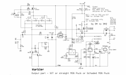
The amp is a Headphone amp (though it would certainly drive speakers), Hybrid, a Triode strapped C3M Tube stage feeding into a Mosfet source follower, the tubes are mounted to the top of the case, with shielded cable running to the Anode Grid and Cathode.

I'm posting here since the noise is something todo with the tube stage

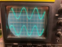
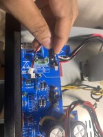
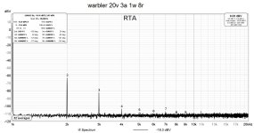
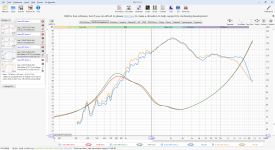
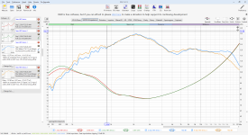
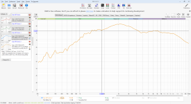
Basically when I power the amp on sometimes I get a 100+mV 60Hz hum out of one or both channels, If I lift the top of the amp (where the tubes are attached), it modulates the hum, completely eliminating it in some positions, and I can always bring it back by picking particular angles for the top of the case. If I take a lead connected to my ground point and ground the shield of the cable running to the tube at the end nearest the tube, the noise instantly vanishes.

I don't believe it's a bad connection, or anything to do with moving the connections. The tube Heater is DC with < 1mV of ripple, There is no AC anywhere near the right hand side of the case where the right channel is.

I haven't had a chance to run a permanent wire to ground from the shield to verify that fixes it.
My best guess at this point is, that the aluminum case top is not grounded because of it's coating, and acting as as antenna, but the size of the noise has me skeptical of that explanation, so I'm just wondering if anyone else has experienced something similar, and has a better explanation.

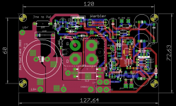
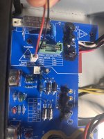
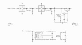
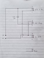
B+ is 150V, the Anode current is ~10mA, there is a 2K2 grid stopper not depicted in the diagram because it's mounted on the incorrectly labelled tube socket.
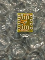
On the C3M connection 1 is Anode, 2 is Grid, 3 is Cathode

1725384697875.png


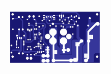
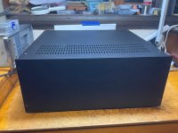
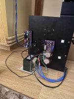
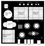
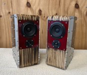
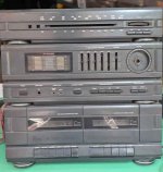
And the Case for illustration purposes

1725384933629.png


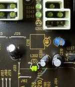
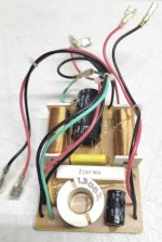
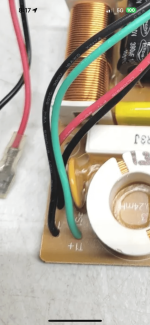
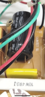
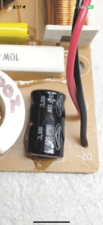
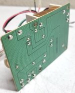
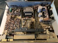
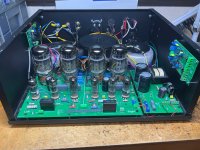
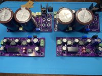
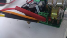
And the internal layout, Pre boards are at the top on the outsides, Disconnected orange wires are for the tube heaters.

1725385128599.png

Citation 2024

Have completed my Citation II upgrade to a pcb base unit. My post last December 2023 had start hum and buzz problems.
After 8 months have all the problems solved. The new unit I call Citation 2024.
The corrections were the following:

1. New main pcb, left & right channels totally isolated except for power and ground.
2. Added two 50 ohm resistors to ground on each of the 6.3 VAC heater lines.
3. Added .1uF 630Vdc caps on -69VDC and +460 VDC outputs.
4. Added a 10k 1/2w resistor across the 1 M input resistors.
5. Added a Speaker Dethumper relay on speaker outputs. Delay time 45 seconds.

Been running for a week, sounds great .

Attachments

  • Gerber_files.zip
    Gerber_files.zip
    1.9 MB · Views: 59
  • Schematics.zip
    Schematics.zip
    883.6 KB · Views: 118
  • PDF.zip
    PDF.zip
    3.5 MB · Views: 86
  • 2k Dual channel.jpeg
    2k Dual channel.jpeg
    549.8 KB · Views: 130
  • 10K square wave.jpeg
    10K square wave.jpeg
    484.4 KB · Views: 114
  • Case_topview.jpeg
    Case_topview.jpeg
    612.3 KB · Views: 117
  • Case frontview w Cover.jpeg
    Case frontview w Cover.jpeg
    442.9 KB · Views: 135
  • Front View.jpeg
    Front View.jpeg
    607.3 KB · Views: 129

Lost 1 Channel on SSE

Good afternoon,

Like the title says, list one channel on my SSE after about 6 years of steady use. It would get quiet and fuzzy on occasion once in awhile, but barely puts out any sound now(have to put ear to speaker to hear anything).

For fun I opened it up and swapped all the wiring on to the output transformers to see if that was the issue, but after switching the wiring to OT’s same channel was still out. Are there any specific areas I should be looking at when I open it up and start testing with the multimeter? Thanks in advance!

Alex

Hi all!

Hi, new member from Sweden, been reading and learning a lot from here during the years, but time to post now 🙂

I am an old cable and satellite service and repair guy, been collecting and restoring vintage hifi for a while now and have for the moment quite a lot of gear in the house. In my main system there are Yamaha C2 preamp and T2 tuner, which feed an M4 power amp, the turntable it's a rebuilt Thorens TD-150, speakers are JBL L166.
Secondary system is Yamaha A1 amp, T1 tuner and Technics SL7 tangential turntable feeding a pair of NS-1000.

Have built some stuff to, a Pearl2 phono amp and a JLH 69 power amp.

So see you around in the forums 🙂

Cheers,
Hans

Irremediably pushed DIY

Hi,

I'm French but live in Italy. I'm in my 40s, always been around HiFi due to my father's obsession with it. Being an electronician by trade, he loved buying broken gear and repairing it, as well as hoarding all the tubes he could find. I never could understand that desire to keep buying with the intention of repairing but never finding the time to do it. This did nonetheless have a lasting influence.

I use a couple of Hiraga Class A Amps along with a Yamaha CA 800 II. One built by my father(8W), the other one built by me (20W). I have 3 pairs of Supravox speakers: 2 TQWT that I built and a Jensen (bought from another DIYer in Italy). I stream my music through a couple of RPI feeding a Cyan2 and a Protodac. I have some knowledge in electronics to be able to follow a schema and solder pretty well but nowhere near being able to understand the fundamentals behind design choices.

Cambridge audio topaz am5

I bought Cambridge audio topaz AM5
Power button Light blowed i checked there voltage it shows dc 70v.
It was a small led for power up light why is that much voltage there??? Amplifier works fine but small sound balance only works right side when I increase volume sound comes back to normal both sides what causes this ????

Attachments

  • IMG_8451.jpeg
    IMG_8451.jpeg
    417.5 KB · Views: 55
  • IMG_8448.jpeg
    IMG_8448.jpeg
    354.8 KB · Views: 52
  • IMG_8447.jpeg
    IMG_8447.jpeg
    459.7 KB · Views: 50

For Sale PCBs for Super Mofo (with pucks) and for a high current filter + negative rail generator

Hello,

I have for sale the pcbs for an improved version of the Mofo and the pcbs for the power supply for it.
This one has better bias control, better high frequency performance, doesn’t need a low output impedance preamp to drive it so you can easily use valve preamps too.
There is another interesting part, the power supply which generates a negative rail through an isolated dcdc converter which gives the posibility to use SITS without worrying about the inductor’s resistance when biasing the transistor.
Both the positive rail and negative rails are filtered giving very low noise.

2x amp pcbs + 2x ps pcbs sold

Attachments

  • IMG_6476.jpeg
    IMG_6476.jpeg
    783.3 KB · Views: 334
  • IMG_6482.jpeg
    IMG_6482.jpeg
    465.9 KB · Views: 359
  • IMG_6483.jpeg
    IMG_6483.jpeg
    437.1 KB · Views: 358
  • IMG_6490.jpeg
    IMG_6490.jpeg
    206 KB · Views: 335
  • IMG_6487.jpeg
    IMG_6487.jpeg
    463.7 KB · Views: 345
  • super mofo.jpg
    super mofo.jpg
    70.9 KB · Views: 338
  • filter.jpg
    filter.jpg
    40.5 KB · Views: 335
  • warbler 30v 4a 25w 8r.jpg
    warbler 30v 4a 25w 8r.jpg
    208.3 KB · Views: 269
  • warbler 30v 4a 35w 4r.jpg
    warbler 30v 4a 35w 4r.jpg
    209.1 KB · Views: 258
  • warbler 30v 4a 1w 4r.jpg
    warbler 30v 4a 1w 4r.jpg
    203.4 KB · Views: 193
  • warbler 30v 4a 10w 4r.jpg
    warbler 30v 4a 10w 4r.jpg
    205.4 KB · Views: 188
  • warbler 30v 4a 31w 4r.jpg
    warbler 30v 4a 31w 4r.jpg
    208.2 KB · Views: 184
  • warbler 31v 3.2a 33w 8r.jpg
    warbler 31v 3.2a 33w 8r.jpg
    210 KB · Views: 151
  • warbler 31v 3.6a 33w 8r.jpg
    warbler 31v 3.6a 33w 8r.jpg
    210.2 KB · Views: 140
  • warbler 31v 3.8a 33w 8r.jpg
    warbler 31v 3.8a 33w 8r.jpg
    209.8 KB · Views: 221

A brief history of ICEpower

https://audioxpress.com/article/focus-computation-of-bass-reflex-alignments

And coincidentally i was at AES 1999 in NYNY when they first showed their product and i spent some time talking with the founders. I didthis little web page bit, https://www.t-linespeakers.org/oddsends/ICEPower/index.html on what i saw.

Later they asked me to take it down, they said it was OK when i said it was soley for historical purposes.

dave
  • Like
Reactions: ICG and yys310

Playing 24-192 files with Sonic Frontiers SFD2 Mk2

Hello

I got a Sonic Frontiers SFD2 MK2. Presently, I'm listening music by Qobuz in my Melco N1z 6T connected to an Aufio gd DI-20 interface with the USB yo SPDIF of an Aqua LaVoce Dac.
I simply love the old SFD2 which was refurbished but I can only listen 16/ 44-48 kHz files
I can't select the sampling rate with the interface,
Question:
If I use a chip like the WM8805 to replace the Ultraanalog SPDIF receiver in the SFD2, will I hear high resolution files with this dac truncated to 44 -48 kHz or the Ultraanalog chips which goes to 48 kHz will not let files over 44-48 kHz play ?

Any other solutions ?

Thanks

Martin Logan Descent subwoofer blown amp

My MartinLogan Descent amp developed a problem. Everything still "works" but it produces very little volume with minimal excursion of all 3 woofers.

ML says that the amp is dead and they no longer have the part (the entire back plate). Anyone know how to repair this or have suggestions? Here are some pics of the back plate which includes all the electronics and amp, and I've attached the service manual and schematics provided by ML.

This was a really nice sub despite its age, would be a shame to dispose it.

1674096570600.png


1674096562338.png

Attachments

Just finished building another tube amp

6V6 power tubes, PP and 6J9P drivers was designed by Doug DeYoung at Bugamps, he was kind enough to give me circuit boards, which saved me from a total point to point build. I designed the layout and grounding. I make my own enclosures. I have a YouTube channel (not monetized) and uploaded a build video.
https://youtube.com/@cytowing3353?si=nd-S5qGDchk2NhHR
20240903_214033.jpg
  • Like
Reactions: vinylkid58

Bass equalizer modules, are they identical?

I'm studying the active bass equalizer system to be applied for my speaker system. I wonder whether the "B&W Bass Alignment Filter" and "Linkwitz Transform" are the same thing?

From my research, the B&W's, when installed, would alter the order of the bass loading system to a higher order, i.e., when used with the ported speakers, it will shift the original fourth order to sixth order system as explained in its brochure and many reviews. For the Linkwitz Transform circuit, it would delete the original alignment and create a new alignment instead, whilst retain the original number of order, i.e., a closed box with Qtc of 1.0 and Fb of 50Hz could be shifted to Qtc of 0.5 and Fb of 35Hz, STILL, the number of order will remain second order HPF. And for the ported system, it would not shift the order from fourth to sixth but remain the forth order HPF.

Is my understanding correct? In all, should I build the LT circuit myself from the online resources or buy the B&W's module (luckily, it allows user to change settings to suit various speakers as it's claimed itself to be universal use)?

The objective is to extend deep bass response of the closed enclosure speakers.

Subwoofer for Neumann KH420

Dear all
I am running a pair of KH420 in a heavily treated room of 23sqm. They are linearised by a Minidsp shd preamp. IN 2022, I built two vented subs with 60l and used the BMS 12S330 powered with a Crown XLS 2502. The sound is very clean and the bass goes low. However, it's not enough for HT or bass intensive music. Therefore, I am eyeing with 2 BMS 18n862 in a sealed box (>100l) positioned in the two back corners of the room. I could go up in diameter size up to 24" and 300l. Any other suggestions?

Cheers
Dave

JLH69 vs Hiraga Le Monstre 2024

So Patrick, you say to bias at 2.88 watt, watt is the point. The amp is less than 25% efficient. Wasn't it designed to be 10 watt into the load. You are looking at +40 watt dissipation (per channel), will that not make them run a little hot. You obviously not built or tested one. Here is mine you can see that it was getting very hot to run at specified power. Power supply is external.

20190420_200604[1].jpg
  • Like
Reactions: hbtaudio and lineup

PARASOUND HCA 2200 & 3500 on Infinity Kappa

Wiill any of these drive Infinity Kappa 8 or Kappa 9 that dip down to 1.2 ohm (K8) and 0.8 (K9) ohm? I see on Youtube those who run Kappa 9. I will run Kappa 8 and I think it does gallantly ... I just can not get together that 2200 on paper only gives 385W in 2 ohms, and 3500 gives 500W, 4 ohms, when they weigh massively, both give 90/120 Ampere, damping factor 1000. Comments are gratefully received! 😀 John Curl ?

(Even my ROTEL RB1080 gives 1000W@1ohm whuch is a lightweight constructions, +200 Ampere, damping factoring 1000)

Eltax Century 200 - Speaker & Wiring Query

Hi All,

Hoping you can help me out. Have done a quick search on this but to no avail so here goes.

I have recently been given a pair of Eltax Century 200 floor standing speakers. 3-way ported config. 80w RMS @ 8Ohm.

When i plugged them in i found that both tweeters have blown. 🙁 .... no wonder they were being given away!

Also, one has significantly less bottom end, hmmm. The woofers seem to be okay, as does the capacitor between the top woofer and the tweeter - tested with a multimeter

I'd love your opinion on the following please?

1. Is it worth me sourcing replacement tweeters or would i be better off scavenging them for working parts? No idea if these units are any good or not.

2. Why would i be getting less bass from one of the units?

3. Having pulled the drivers out to inspect, the exiting blown tweeters don't have + or - on the terminals - does it matter which way they are connected (other than potential phase issues - although led to believe this would be nominal for tweeters)

Below is a wiring diagram I've put together (apologies for my poor drawing skills - hope it makes some kind of sense!) - hopefully that will help make some sense of the config / wiring.

S1 & S3 = Woofers
S2 =Tweeter

If any other info would be useful then please let me know - newb to speaker electronics / wiring here 🙂

Look forward to hearing from you, and thanks in advance.

Tim

P.s. Looks like someone had been in there before me so can't vouch for whether the wiring is how it should be
P.p.s I'm usually on the mixing desk, not poking about in stereo speakers so please be gentle and excuse my ignorance 🙂

Attachments

  • 20240902_184452.jpg
    20240902_184452.jpg
    515.2 KB · Views: 66

Master List of DIY available waveguide dome tweeters

  • Like
Reactions: hifijim

Hello I’m from Florida and I’ve been installing audio for 30 years but I always have new stuff to learn

Choosing which capacitor value is needed to X out vocal frequencies. Currently I’m using 100V2.2uf and vocals are still coming through 🥺. My amplifiers have full range signals going to my tweeters and I have HP going to the from the head unit. I’d like to change the value of these to take out all vocal frequencies completely, which capacitors should I get? Thank you for reading.
IMG_1731.jpeg

  • Locked
Which Capacitor is used to eliminate vocal frequencies?

Choosing which capacitor value is needed to X out vocal frequencies. Currently I’m using 100V2.2uf and vocals are still coming through 🥺. My amplifiers have full range signals going to my tweeters and I have HP going to the from the head unit. I’d like to change the value of these to take out all vocal frequencies completely, which capacitors should I get? Thank you for reading

Thoughts on single-ended amplifier layout

I'm building a Tubelab Simple SE and was hoping to get some feedback on the layout. I'm a bit cramped for space (13x13" aluminum chassis, with 1/2" border for fixing to the bottom). Mostly I'm wondering about the placement and orientation of the OTs, PT, and choke. From what I can tell, both the Edcor OT and Hammond PT are vertical wound, so I have them 90 deg to one another. But I'm not totally sure about the choke -- it looks to be horizontally wound, so I'm not sure if it's fine as is, or if it still needs to be rotated 90 deg with respect to the PT.

Any other thoughts would be appreciated. E.g., Should I swap the choke/motor run/PT? Are the OTs too close to each other or to the speaker outs or PCB? Any other drastic changes I should consider? (Note that the choke will be mounted underneath, and the volume and switches will be affixed to the front panel.)

Thanks!

Attachments

  • Final_design.png
    Final_design.png
    64.7 KB · Views: 141

Dropping in a balanced out solution on my DG-1000

Hello again.

I am designing a breakout board to replace IC205 on my DG-1000 preamp, in order to add a balanced output jack. I am planning on using it add a THAT 1646 balanced line driver in addition to an OP275 (replacing the NE553) driving it. I just wanted people's thoughts on the implementation - I plan on following the suggested circuit schematics on the datasheet for the 1646/1606.

Is this a good implementation of a balanced output for audio equipment?

Thanks in advance for any input.

BT-201 bluetooth board, firmware question

Hi all. I am into making DIY bluetooth seakers, so naturally have been getting various bluetooth or bluetooth enabled boards from aliexpress. I recently found the board that satisfies my every need, BT-201 (and BT-301). It has bluetooth audio channel, data channel, USB and TF card playback. BT-301 has line in and even FM radio. Both have huge AT command set to be used via serial port.

The boards could be flushed with newer firmware easily, that comes in updata.bfu file. The latest virsion I have intalled on the board when purchased is VER2.3-20200927 but I dont know where I can find the download.

Would anyone know where can I get latest documentation .zip (usually contains firmware file in it as well)? I have VER2.3-20191115 file, but it is quite a bit older.

Does it exist a variable inductor for easy crossover fine tuning

Hello all, do you know where to buy, if exists, a low DCR and high current variable inductor to help in crossover fine tuning? I hate unwind and rewind normal coils, also because they can easily be damaged from this practice, so I'm wondering if exists an inductor where I can simply move the inside core in & out to change the mH value, or at least what can be the best suitable in commerce inductor in which this tweak can be easily done.
Obviously I talk about both low DCR & high mH inductors for low-pass section both medium DCR and low mH value for the high-pass one.
Thank you very much.

Split bias from one winding?

I am losing my ability to reason as I approach my 7th decade. Can someone help me to think please? I dug out my room heater project to clean it up a bit for the winter. I built a pair of monoblock 6C33C Push Pull Parallel OTL amps a couple decades ago, and they sound excellent. I originally built it with what I had laying around, the transformer count is high and very heavy. I would like to replace the 6 pound bias supply transformer with a small 25VA-ish toroid. Bias is -60 in relation to 0V, and -60 in relation to -150V. Can I just run 2 bridges off one transformer winding without exceeding some unknown limite? Current schematic (- a pair of output tubes) below..
6C33v8.2.jpg

Hi!

My name is Michael and I have a deep passion for listening to music, and I’ve invested in a PA system to elevate my listening experience. I'm particularly drawn to the bass, as it adds a powerful and immersive element to the music. I love experimenting with my setup to fine-tune the bass, seeking that perfect balance where it’s punchy, clear, and resonant without overpowering the rest of the sound. I'm always exploring new ways to enhance and refine this aspect, whether it's through adjusting the settings, upgrading equipment, or tweaking the acoustics in my space. My goal is to achieve a sound that truly resonates and elevates the overall listening experience

Headscratcher (for me) with Pioneer A400X protection

Hopefully in the correct forum.....

I'm going a bit mad trying to trace a problem with what I think is false triggering of the protection circuit on a Pioneer A-400X amp.

There seem to be no apparent problems with DC offset (about 2mV on each channel). After being left switched off for a while the amp will happily work for maybe 40 minutes (with a signal) then the protection kicks in. With no signal the protection kicks in after about 10 minutes from cold but when warm the amp might never come out of protection or will almost immediately go back in to protection after the startup delay. (Is the no signal thing a clue?). There seems to be either a temperature or residual charge element to this perhaps?

However, when the protection kicks in there's no indication why that I can see - no DC offset, overloading didn't happen.

I'm thinking its the protection circuit false triggering and so I removed transistors Q303 and Q304 which I think detect DC offset and also the resistor R308 which connects to each channel's overload detection. That changed nothing and I can't see how!

Am I right in thinking that protection is triggered by either the DC offset detection or overload circuits pulling the base of Q305 low so that it turns on and discharges C305 - that in turn results in the relay being deactivated. Once Q305's base has been pulled low it latches itself on by virtue of its base current through R309?

I've replaced C304 incase that was leaky, Q305 itself and C305 but no effect. With the components named above removed I can't see what is able to switch Q305 on. Once triggered the voltage at C305 cycles varying between about 4 and 18 volts.

The supply voltages on the B+ and B- are both 42.9v of the specified 43.3v and the protection circuit has its own supply bang on at 41.9v (albeit with about 1v of ripple despite having changed its filter cap too).

I can't see how this fault might be caused although D306 and D305 are a bit mysterious to me - some kind of over-voltage protection?

Any ideas? - I can no longer see which components might be responsible!

Notes on the attached circuit diagram - the power for the protection circuit comes via D308. The "bottom" of R311, R316 et al go to ground.
A400XPartDiagram.png

DC MC low noise input stage with Bias Cancellation idea

I was looking at some phono stage designs and didn't like the typical asymmetrical stack of paralleled transistors, put in the feedback loop of an op amp.
It seems super unbalanced and would be impractical to get good THD performance at low frequencies since it's all AC coupled.
So to make a simpler circuit I sketched up this overkill one.
It's a symmetrical set of szlyskai pairs; Bases tied together, which is the input.
The supplies of which are fed from a pair of op amps that give negative feedback to the circuit (all DC coupled), and also bias the circuit.
The idea being that the 2 symmetrical pairs balance the bias current. Would the noise from these being in parallel cut down on the noise?

Then there's a synthetic load, which I included in the circuit so I could ask about the noise.
In Self's book he mentioned that he had concerns about the noise from the synthetic load input going back into the signal chain. But wouldn't that cut down on the noise?
If you connect 2 op amp inputs together wouldn't the noise be the result of the sqrt of the 2 noises combined?
phono amp idea.png

Tiny Translam Transmission Lines

I thought you guys might enjoy these. I made them as a gift for a friend who always wants to know how stuff works. 😏
Offset driver TL design done in Hornresp, physical design done in Fusion360. The layers were cut on our 80w laser. Alternating layers of 6mm ply and MDF. After gluing, I quickly ran the belt sander over them to end up with a bit of a steampunk look. Drivers are SB12PFCR-4 and Dayton TD20F-4. I used the foam for stuffing since it has very little weight for its volume. It looks a bit funky- one bit on one side and one bit on the other, but it is as calculated in Hornresp. Any more kills the LF and when I tried less, they sounded boxy.

The acrylic sides do vibrate very slightly at high volume, so I’ll readily admit that they are not perfect - but they do sound very very nice. By far the most expensive cabinets I have ever built!

#translam #tl #transmissionline


IMG_4247.jpeg


IMG_4233.jpeg
IMG_4232.jpeg
IMG_4180.jpeg
IMG_4211.jpeg
IMG_4220.jpeg
IMG_4270.jpeg
IMG_4271.jpeg
IMG_4273.jpeg
IMG_4272.jpeg

Ve

Attachments

  • IMG_4247.jpeg
    IMG_4247.jpeg
    609.7 KB · Views: 64

Lamination Datasheets

Hey guys ! I was hoping for some help trying to pin down some datasheet with any Inductance equations for the a lamination I purchased. I got it from a pretty shady shop with no data on manufacturer , composition or even part number. I have determined the dimensions do line up with the EI-114 type.

It seems to be some form of silicon steel to the eye , although Si% is hard to determine. I would assume somewhere around 4% as that is the most common for purchasable domestic transformers in our country. They have a thickness of ~0.5mm (calculations show somewhere around 0.496mm).

Ultimately what I'm looking for is an equation that will show what N primary turns is needed to get some L Inductance value in the core. For example, from Robert G. Wolpert's book he found a catalog for his lamination with the equation L = .9283 * 10^-8 * K * U ; where K is the stacking factor and U is permeability of core material.

Thank you for the help !

Audiolab 8000 A bias issues

ok here is a few facts and a few questions around the audiolab 8000 a

---First to notice that units in production till 1992 are equipped with 220V trafos so many of these units with now days 230-240 voltage in Europe will produce almost 43 +43 volts after the capacitors and these few 3-5 volts more per rail will eventually stress the amp and coloration of burned pcb will be there

---Also noticed that either after year 1992 trafos are different so with 230Ac produce almost 40 Volt ( or they simply realized that they are stressing the wrong circuit with the wrong ways.)

---the audio lab 8000S is an sziklai or CFP if you like that means that the double VBE multiplier lays on the drivers .

---Let us forget for a minute the weird bias procedure where a tech is requested to remove covers install probes re install covers and adjust the bias 😱😱😱

---Real problem is that the ventilation designed works only for the outputs and the rest of the amp is tight sealed where in the driver area temperature will increase then the Vbe multiplier will drop the bias according to the temperature ....probably over compensate and reduce the bias more than needed .

so Solution 1 will be to almost over bias the amplifier and expect the VBE multiplier to finally adjust something more reasonable when the pcb are will reach the ""operating'' temperature

Drawbacks will be
--that you still going to stress the pcb and parts around the amp
--will take quite a lot of time for the amp to stabilize a temperature
--And don't know why but i still think that there is still going to be some thermal run away

or Solution 2 drill fins or long ventilation halls above the driver area
---Bias the amp to the manual stated bias
---Defuse all the concentrated heat from inside the box
---Allow the Vbe multiplier to adjust the bias only when amp is stressed

i dont see any drawback here ....


opinions please

kind regards
sakis
  • Like
Reactions: GAlmeida

SEAS 87H 1968 test

Test seas h87 1969, disassembled and centered with Arta/Limp and dats v3, for their age they are very good, we are looking for these mid/tweeters for something fullrange alnico, about the same age, I want to build something omnidirectional only with old speakers, for amplifier on lamps.
IMG20240902142710.jpg
IMG20240902162610.jpg

Attachments

  • IMG20240902162648.jpg
    IMG20240902162648.jpg
    319 KB · Views: 112
  • IMG20240902162735.jpg
    IMG20240902162735.jpg
    268.9 KB · Views: 102
  • IMG20240902162813.jpg
    IMG20240902162813.jpg
    255.1 KB · Views: 129
  • REW V5.31.3 9_2_2024 7_40_59 AM.png
    REW V5.31.3 9_2_2024 7_40_59 AM.png
    87.2 KB · Views: 154
  • REW V5.31.3 9_2_2024 7_41_10 AM.png
    REW V5.31.3 9_2_2024 7_41_10 AM.png
    117.9 KB · Views: 131
  • REW V5.31.3 9_2_2024 7_41_19 AM.png
    REW V5.31.3 9_2_2024 7_41_19 AM.png
    159.4 KB · Views: 116
  • REW V5.31.3 9_2_2024 7_41_28 AM.png
    REW V5.31.3 9_2_2024 7_41_28 AM.png
    342.8 KB · Views: 96
  • REW V5.31.3 9_2_2024 7_42_10 AM.png
    REW V5.31.3 9_2_2024 7_42_10 AM.png
    73 KB · Views: 88
  • REW V5.31.3 9_2_2024 7_43_01 AM.png
    REW V5.31.3 9_2_2024 7_43_01 AM.png
    82.7 KB · Views: 89
  • REW V5.31.3 9_2_2024 7_43_14 AM.png
    REW V5.31.3 9_2_2024 7_43_14 AM.png
    63 KB · Views: 95
  • REW V5.31.3 9_2_2024 7_43_22 AM.png
    REW V5.31.3 9_2_2024 7_43_22 AM.png
    60.2 KB · Views: 84
  • Seas H87.mdat
    Seas H87.mdat
    4.6 MB · Views: 355
  • Untitled - Limp 9_2_2024 7_20_20 AM.png
    Untitled - Limp 9_2_2024 7_20_20 AM.png
    23.7 KB · Views: 83
  • Untitled - Steps 9_2_2024 7_47_41 AM.png
    Untitled - Steps 9_2_2024 7_47_41 AM.png
    27.4 KB · Views: 83
  • Like
Reactions: SunRa and jimk04

Schiit Urd : USB audio to USB-input DAC

I like the looks of the Schiit Urd transport. It is a bit pricey but uses a rare these days high quality all metal cd drive. Cannot find much discussion here about it though. Does it have glaring flaws or something?
I just discovered the Urd, with its USB Audio output that can feed a USB DAC. Having designed a number of USB devices and hosts, I am familiar with the USB Audio mode where the destination can control the rate of data from the source, and I wonder if there is any combination of Urd + USB DAC that uses this feature.

With USB Audio, if the source happens to be running a little faster or slower than the destination, a low-bandwidth communications channel on the bus allows the USB Host to reduce or increase the number of audio samples in future buffers to keep the source in sync with the destination. This avoids real-time sample rate conversion, and also avoid complicated PLL systems to match the rate of the DAC to the media. Ideally, the USB DAC would run from a high-quality local sample clock, without any PLL circuits to slave to an external clock.

For this USB Audio feature to work, a USB DAC Device would need to implement this mode. There are three audio modes, I recall, so there's no guarantee that a USB Audio Device DAC would necessarily use the best mode. In addition, the Schiit Urd as USB Host would also need to implement this mode, and in particular would need to slow down the CD transport motor, or speed it up, in order to adjust the rate of audio data flow to match the DAC clock.

Does anyone have any idea whether all of the pieces are place for this to work?

Brian

Sonodyne Uranus FM 3000

I have a Sonodyne Uranus FM3000 model. Which is the last Sonodyne model before they stop their business initially from India. This machine was unused for several years and now I want to make it back to working condition. Can any one help me by providing Service manual or Schematics?

Thanks in advance.

Not: I may have posted this message to wrong section. If I have done wrong, Admin please put it in right place.

Attachments

  • 434564900_804447478217716_8294225463149822933_n.jpg
    434564900_804447478217716_8294225463149822933_n.jpg
    73.6 KB · Views: 156
Projects by fanatics, for fanatics
Get answers and advice for everyone wanting to learn the art of audio.
Join the Community
507,572
Members
7,877,493
Messages

Filter

Forum Statistics

Threads
405,749
Messages
7,877,493
Members
507,572
Latest member
NakajimaYusuke