Hi everyone!
I have this amp (Hertz HCP 1D) burned badly under mainboard....few parts missing/melted - also lost copper tracks.
Does anyone have pictures of this amp under board, good guality so maybe I could re-do those tracks 🙂 Or schematic could be even better!
Thank you!
Also coil at speaker output is burned/melted :/
Hello, maybe I can find a picture and also the sch of the damaged area but it is better
you make a picture of the area to realize the problem
you make a picture of the area to realize the problem
Thank you both for your answers.....ppalli: I would need a picture from the corner underneath output coil.
The amp is already packaged and throwed into storage but I can go and get it if you need me to do so 🙂
Also, if anyone knows what mH is that output coil....that is also to be replaced :/
The amp is already packaged and throwed into storage but I can go and get it if you need me to do so 🙂
Also, if anyone knows what mH is that output coil....that is also to be replaced :/
I hope this may be usefull: D40-D41 are ES1D, coil is 18uH-25A, mosfet are IPP200N15
An externally hosted image should be here but it was not working when we last tested it.
Okay..changed those parts showed on picture above, now the amp power is working properly, producing +/- 48V rail voltages.....but something is still wrong at amp -section :/
Power on, the led is red but blinks a short green between about 5 second cycle......what could still be the problem? IRS maybe?
Amp produces a 600mVDC at speaker output when no load (and no signal input) is added, if i place a 8ohm resistor to speaker output -> reading drops to zero (0,003-0,008)
Power on, the led is red but blinks a short green between about 5 second cycle......what could still be the problem? IRS maybe?
Amp produces a 600mVDC at speaker output when no load (and no signal input) is added, if i place a 8ohm resistor to speaker output -> reading drops to zero (0,003-0,008)
No Perry...not the actual rail-to-rail oscillation, when it blinks green there seems to be a short (only negative) voltage ´bang´ - looking mostly triangle
I don't have any information on this amp but, in general, when the output transistors fail, they destroy the driver IC if the output transistors are driven directly by the IC. Did the output transistors fail?
Yes they did.. I would already changed that driver IC if I only had it in stock 🙂 Broken parts were, output transistors and those D40/D41 ES1G´s were blown away along with some copper lines.....but I have a strong feeling that they´re okay now 😀
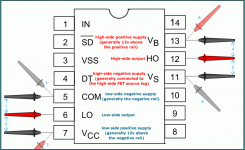
On pin 3 at IRS20957 is nothing - the same ´blinking´ ..............
When I input 1Vrms/50Hz sine - pin3 has good (for my eye) input but outputs pin10 (LO) has nothing and pin14 (HO) gives 0,5VAC sine.......speaker output has 0,5VAC sine
When I input 1Vrms/50Hz sine - pin3 has good (for my eye) input but outputs pin10 (LO) has nothing and pin14 (HO) gives 0,5VAC sine.......speaker output has 0,5VAC sine
Last edited:
If you want to remove it and check it (as well as you can with a meter), you can measure the resistance between all 3 terminals for each output section (HO and LO). There shouldn't be any readings less than about 10k ohms. Most will read in M-ohms.
Removed the IC and ordered few new ones.......we´ll see what happends, thank you Perry for your effort! 🙂
Before changing the IC, I would also recommend to check the low value resistors, 0 to 20 Ohm around the IC and near the 270nF cap, and diodes for short circuit
It 's very important to change the 270nF capacitor that is shown in the picture, it is very important 'cause it's the feedback of the amplifier stage. Its correct value gives approximately 350kHz oscillation, if it is open the frequency drops to few kHz and the amplifier's idling current will be very high.
It 's very important to change the 270nF capacitor that is shown in the picture, it is very important 'cause it's the feedback of the amplifier stage. Its correct value gives approximately 350kHz oscillation, if it is open the frequency drops to few kHz and the amplifier's idling current will be very high.
Okay..changed IRS and LM311 next to it, also rechecked the value of the capacitor -> 272nF
No progress happened, only thing that changed is that red light is now constantly on - no green blinking anymore 🙂
Any ideas for now on?
No progress happened, only thing that changed is that red light is now constantly on - no green blinking anymore 🙂
Any ideas for now on?
The layout for the IC below is different than yours (IRS20957) but the pins are labeled the same. Check each of the two output sections to confirm that neither has any leakage or shorts between the pins.
Even though this is a new IC, it's possible that it was damaged when installed. All should read in the M-ohm range. If you read anything significantly lower, compare the readings to that of a new (uninstalled) IC.
Even though this is a new IC, it's possible that it was damaged when installed. All should read in the M-ohm range. If you read anything significantly lower, compare the readings to that of a new (uninstalled) IC.
Attachments
- Home
- General Interest
- Car Audio
- Hertz HCP 1D Picture/Schematic