TPA3255 PCB Design - Corrections and Suggestions

Hello.

I've been digging around and trying to know more about making an amplifier. I have decided to make something, that is hopefully not too big of a mouthful for me. We all have to start somewhere, and for me, that somewhere is here.

I hope i can get some feedback of the parts list and possible some recommendations for changes to the parts list. As soon as I, hopefully, have received some feedback, and corrected the parts list, I will try to make the PCB layout and post it in here.

The end goal is to have a couple of boards for my own use.


What do i want out of this project:
I want a PBTL mono amp (switchable to BTL Stereo if possible), that also has a build in 5v 1a output for an Arylic Bluetooth Receiver.
Be somewhat on a budget.
Has to play clean, but I do not need something over the top.
Possible a change of OPamps if it is worth it, to spend some extra
A reliable amplifier, that can be used for a party speaker and/or some nice mono speaker for the living room.


... I considered adding PFFP to the board, but i honestly do not think it is worth it for this project. Correct me if I am wrong.

I also dreamt about having 3 chips on the board, and DSP, making it real easy for crossovers for my projects, but unless I have a schematic I can follow, this will be too complicated.


Parts list:
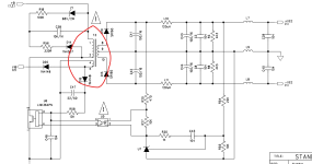
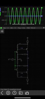
I listed my parts list below. That is including the schematic and parts list for the voltage converter for the 5V 1A.
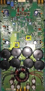
All the green markings are items, that have been changed from the reference design schematic. If you have any tips of changes in values, parts etc., please let met know.

Attachments

For Sale (UK) Hypex Fusion FA123, Faital HF10AK/LTH102 & Seos 12

Having a bit of a clear out from the DIY speaker stuff, I’ll keep some of the drivers and bits and move the rest on so the following are up for sale.

For anyone in Mainland UK, postage included in the price, and can be collected from Oxfordshire. Happy to quote for postage outside of UK but might not be competitive cost wise.

Pair of Hypex Fusion FA123 3-Way DSP Amplifiers £SOLD inc Postage
Comes with all the various cables and the remote unit too.


20230810_165323~2.JPG


Pair of Faital Pro HF10AK £SOLD inc Postage
Superb condition and come with the original boxes.

Happy to include the pair of LTH102 with these for £220 in postage all in.

20230618_095117.JPG


Pair of Faital Pro LTH102 £60 inc Postage
Essentially as new, only used a couple of times.


Pair of Seos 12 £100 inc Postage
These are in an unfinished white primer, these were sold as made by Autotech although I have no paperwork to confirm that.

20230618_095001.JPG

20230618_094859.JPG

For Sale Musical Affairs Mini Baffles

Selling a pair of Musical Affairs Mini Baffles

With EMS Fertin LB12EX field coil drivers

Beautifully hand built by Hans Kortenbach and the power supply for the field coil drivers has been made by Cees Pel

Speakers can be listened to and picked up in Eindhout, Belgium
If needed I can also deliver the speakers or meet in the middle

Asking 2900€obo

Attachments

  • IMG_4221.jpg
    IMG_4221.jpg
    318.9 KB · Views: 79
  • IMG_4222.jpg
    IMG_4222.jpg
    237.2 KB · Views: 78
  • IMG_4224.jpg
    IMG_4224.jpg
    301.2 KB · Views: 72
  • IMG_4225.jpg
    IMG_4225.jpg
    457 KB · Views: 75

Thoughts on this 3 way design?

I have a pair of Fostex FW305 woofers which are 12 inch -95db /watt sensitivity.I have found this 3 way design in the Madisound library.I was hoping to achieve a medium sensitivity easy to drive speaker and this appears on paper to achieve this.I would have preferred a paper cone midrange but happy to give the Scanspeak treated fibreglass Discovery mid a try as they are not too expensive.The Peerless ring radiator tweeter I am familiar with and have always found it neutral and reasonably detailed.
Any thoughts?
What is the purpose of the two 20 R resistors on the woofer/ A Zoebel network?
There is no recommended baffle width.I am guessing given that the mid and tweeter are estimated to retain close to their natural sensitivity it would need to be reasonably wide.Is this a likely to be a correct assumption?
https://www.google.com/url?sa=t&sou...cQFnoECCkQAQ&usg=AOvVaw2pMh272qqTLXjm37FG-M-T

  • Poll Poll
XXL room with 100 people

What is the best loudspeaker compromise for playing music in a very large 150m2 room with 100 pers.

  • MEH (synergy/unity)

    Votes: 7 70.0%
  • Large horns (Klipsch heritage/JBL)

    Votes: 5 50.0%
  • Infinite line arrays

    Votes: 1 10.0%
  • Open Baffle

    Votes: 0 0.0%
  • Infinite Baffle

    Votes: 0 0.0%
  • 360 omnidirectional

    Votes: 1 10.0%
  • Bipole

    Votes: 0 0.0%

What is the consensus? Which type of speaker gives the best coverage, intelligibility and wide sweet spot (forget about pinpoint imaging for 100 people....just the best vague general stereo image for the maximum amount of people)

Let's assume a 3m or 3.50m ceiling height. Part of the room can have a raised floor for better line of sight over the front of the crowd.

You can choose a maximum of 2 options.

Intro into Lee - Building Ian Canada Streamer and Gabster TDA1541A DAC

Hi all,
Just a quick intro into me, Hi im Lee, I live in Queensland Australia and im currently looking at building an IanCanada Stream and Gabster TDA1541A DAC with UCPure Quad power Supplies...

Just currently doing a lot of reading on some VERY long DIYAudio threads, but so much great experience and info, its really useful.

Cheers,

Lee.

Hypex UCD2K

Hi everyone.

Maybe someone can advice.
I got a Hypex UCD2K power amp module and a Hypex SMPS3KA700 PSU.
1 one these are faulty. The Amp doesn't work..
How can I find out which one is broken ?

I tried to measure the SMPS one the pins I think is secondary power. It did,nt show anything but I,m not sure if I,m doing it right.
Or if there is some "sense" funktion waiting for input signal to function..

Can someone advice?

Regards
/JZ

[Beginner] is 80-5000Hz from a sealed 14L cube possible?

Hi,

If possible, how would you go about getting 80-5000Hz from a sealed 14L (internal volume) cube, if not, what subset of that FR would be achievable?

According to the sub datasheet (SVS 3000 Micro) they can go as high as 240Hz and perhaps I could possibly cut over to the tweeter (Fountek NeoX 3.0) a bit lower or even higher?

I'm thinking of the new speaker sitting in front of my subs (dual 8" opposing) and a separate ribbon.

I'm going to use an 8-ch DAC and CamillaDSP for the crossover and so only two drivers max in this cabinet.

I don't listen to music particularly loud, 50% volume, room is 5x5m. Current system is around 30w of amplification going into 88dB speakers.

Thanks.

advice needed, Monitor Audio RXW-12 Subwoofer power supply

Hi and thank you for taking the time to read my post,

I have searched and yet to find anything relating to this subwoofer

I have a Monitor Audio RXW-12 powered subwoofer, now the amp just appeared to be dead with no signs of life at all and i love a DIY challenge, I've looked around inside and couldn't get any worth while voltage readings ect from the power supply, so I'm hoping it's just the power supply failure however after my recent experience trying to recap the power supply in my Behringer DDX3216 went badly (so that's going to be a future project hopefully as all the ADC and DAC boards are fine if i can find something to take the 8 I2s input data buses and the 4 out using 16 inputs & 8 outputs, USB or Adat ?)
anyway I've given up on switch mode power supplies and wishing to just replace it with a good old transformer as i already have some from my past project's and salvaged from other gear that's been past repair,

Dose anyone have the service manual please ?

the digital amp board has dual rail power input feeding 2 regulator's L7912CV/L7812CV so that gives the 12V dual rail for the opamps ect

there's another single power supply by the look's of it however i cant see the code on the regulator right next to it because of a cap in the way but chances are it's the 5V supply however will check before applying any power

now there's the dual rail for the main power amp and apart from the main filter cap's being rated at 50v and i haven't had the heat sink off yet to see what class D amp chip's ect it uses so that need's further investigation to see what voltage it need's

any advice on suitable power supply rating's and voltages, specially the main amp supply ?

has anyone else attempted anything like this before ?
modified one of these sub's ?
any advice welcome.....

Service manual would be priceless if any one could help,

If all else fail's i will be looking for another suitable Class D amp board to replace it and building a DIY power supply for it

Cheer's

Advice on CNC'd plywood horn enclosures

I've seen in a few threads people have put pictures of large plywood construction folded horns where they did CNC manufacture. I'm going down that path with one of the Woden designs horns for some Alpair 10P that I've been breaking in. There's a couple local shops that do custom CNC plywood work and claim to have a decent supply of good voidless plywood since that's usually what you want for CNC anyway. I'm doing the CAD work and things like board thickness, cutting tool size (for dogbone corners) are all constrained so I can adjust after they bring in the material and let me know what tooling they'd use. Generally I'm interested in any advice from anyone who has gone through it, but I did have a couple specific thoughts/questions:

Any advice on how much tolerance to add to the board width when cutting slots? I'll try to ask them to check how much variation there is in the material once they get it, but there's also how much to add just so I'm not having to sand or hammer stuff together. I can't decide if it's worth adding much tolerance on the board length (at each end of the slot) as well, since presumably the CNC itself cuts the length quite precisely.

Any thoughts on how deep to go with slots? It seems like really it's just to align them, the glue is doing the work. I was thinking only 3mm or so deep out of 18mm thick plywood. Going deeper would probably just weaken the sides and would make it more sensitive to aligning the other side when gluing up.

The Ultimate Miro PCM63 DAC JLSounds i2soverUSB Stack

Sold.

Just done up today, one set of complete and tested Miro PCM63 DAC + JLSounds i2sOverUSB stack.
In my opinion, this is the most direct and best combo implementation of the Miro PCM63 DAC.
Sounds wonderful. It is a full, completed DAC, with a pair of AD797 op amp for the IV.
You would need two single op amp to tune the DAC to your taste.

You need +5/-5V and +5/-5v directly to the DAC board. The JLSounds board's 'dirty side' is configured to be powered by the USB Bus ie. drawing +5V from your USB source. This can be changed to be powered from a PSU of your choice if you wish. Can be done very easily by cutting a pcb track under the JLSounds board as instructed by the user guide, and then soldering two wires from pads available on the DAC board out to the PSU. The XO and reclock circuit of the JLSounds is drawing +5V (digital supply) from the DAC board when you stacked and isolation from the USB 'dirty side' is achieved. Very neat and clean design, with full isolation achieved.

Case it up with transformers, PSU, connectors, a pair of op amps , connect it to a USB music source and you are ready to rock and roll.
All high quality parts are eg. Nichicon gold caps, vishay film caps etc etc.
All parts are BRAND NEW including the PCM63P-K chips. They are installed for the completion and testing to commission the DAC.
Even the JLSounds board is delivered today 24 September.

MIRO PCM63 + JLSounds i2sOverUSB III FIO + shipping tracked & registered = USD 345
I am only ready to accept Paypal Family and Friends as payment.
As usual, I will also buy Miro some coffee as a token for his generous sharing.
I have shipped 58 packages to members here to US, UK , asia and Europe, not a single glitch so far.

More information of this DAC here :
https://electrodac.blogspot.com/p/dac-ad1862-almost-tht-i2s-input-nos-r.html
https://www.diyaudio.com/community/...s-input-nos-r-2r.354078/page-209#post-7049224

Information of the JLSounds i2soverUSB board. This is the USB interface that most members agree to be very good for the DAC.
http://jlsounds.com/i2soverusb.html

Tube Amplifier negative Bias Diode type ?

I'm not sure what kind of Diode this is ? 1960 or 1961 years , maybe a zenor or tunnel ? It's got positive 158 vac in on one side and 6 volts out on the other side and no negative voltage. It's on The negative Bias circuit on Two 6l6 GC , goes through two resistors into two 150 volt e caps installed backwards with the positives grounded and it goes out to pins 5 on The 6l6 tubes. I've been trying to look it up but I can't find anything like it . Maybe someone knows what it is or something else I can use in it's place ?

Attachments

  • IMG_20240526_134745.jpg
    IMG_20240526_134745.jpg
    350.4 KB · Views: 226
  • IMG_20240526_134741.jpg
    IMG_20240526_134741.jpg
    315.4 KB · Views: 204

Introducing opensource (GPLv3) streaming solution for SBC

Hello, Fellow Audio Enthusiasts,

I'm excited to share the results of a year-long DIY adventure with you all! After many hours tinkering, I've developed a solution to stream audio from Raspberry Pi 4B with a HiFiBerry Digi2 Pro card to my old and rusty Yamaha RN-602 MusicCast device via optical cable. And now, I'm thrilled to open up the software to the community under the GPLv3 license.

The project is split into two main parts:
  1. Server: Designed to run on any Linux machine with ALSA support.
  2. Client: Works on mobile, desktop, or browser platforms. Currently, the most supported client is Android, with a ready-to-use APK available, and the Raspberry Pi 4B (raspbian) is the most tested server device, with a deb package provided.

Key Features:​

  • Gapless, Bit-Perfect Playback: No resampling is supported at this stage by the player itself, ensuring pure audio quality, you can still configure ALSA or any other framework that has ALSA compatibility layer (i.g. pipewire) to resample, if needed.
  • Qobuz Streaming: Currently, Qobuz is the only supported streaming service (a valid subscription is required), with FLAC as the sole supported format. There are plans to add other formats and sources, including playing from file library.
  • Versatile Client App: Connects to the server over the network and can even run on the same device as the server.
  • Extensible Code: The software includes an addon mechanism, making it easy to extend with other input sources or device plugins. At this point, it has a MusicCast plugin to control the volume manually and automatically using ReplayGain track data provided by Qobuz.
This project is offered "as is," with no guarantees, but I hope it proves useful to others when building their custom audio systems.

Contributions and feedback are very much welcome!

GitHub Link to the Server
GitHub Link to the App

Yours,
MadEnvel

Attachments

  • screencap.png
    screencap.png
    162 KB · Views: 43
  • screencap-1.png
    screencap-1.png
    198.1 KB · Views: 41
  • screencap-2.png
    screencap-2.png
    359.9 KB · Views: 39
  • screencap-3.png
    screencap-3.png
    68.1 KB · Views: 41
  • Like
Reactions: grindstone

I get nice aluminum finish with these disks and Alumicut

I've been surface finishing some 6061 aluminum bar stock making a chassis. These 3M sanding disks with a small spritz of Alumicut are working great and last long. In fact the finish is better as the abrasive clogs, smoother.

https://www.amazon.com/gp/product/B098RL6Q2Z/ref=ewc_pr_img_1?smid=A1ALTAZ4J6A4L6&psc=1

https://www.amazon.com/ALUMICUT-Lubricant-Aluminum-Copper-Plastic/dp/B071K7PNYW/ref=sr_1_1?crid=3E7I9VZ8B09G6&dib=eyJ2IjoiMSJ9.PjCasEKVdsXvlN31vFXVL-jpX0BR_PRGFfCU4OEvskmq3J_uDmh3Yz66DNxHDOVNaTsAsruCP5OiVqIvMH5xcDGLrkxC9FIfhIXIa4EYh6EhOqOZvXdXz9WP8fZpMFgXZIEorLU2kk9YlMqLHBMbfsBSJKgOPODI33hrDq-OuusjIlCs2psvHH8EURk5lwGgwG5ALTA_WxjUMJ_WoiczHe90p6J_4MCFoiGQM_-BC233-j0d_KR2W9NgoAG4JhzMT95HCWokKOu0vVSw0CN7UsOdkrzuL2BCFrGStzxnA2A.OFWV_hkQR67ydlTe1JZ3C2Pxtv3MVouJOQz8s7pZc4U&dib_tag=se&keywords=alumicut&qid=1727740876&s=industrial&sprefix=alumicut,industrial,236&sr=1-1

I thought I'd have to go to finer grits, but I can start and stop at 320! After sanding I'll burnish the outsides to get a typical "brushed finish" aluminum. These are really great sanding disks for aluminum. One tip, keep the orbital sander moving in circles across the piece, not moving longitudinally. This pattern gives a satin finish with no patterns created. I'm using a 5 inch Dewalt cordless random orbital sander.

https://www.amazon.com/ZFE-Burnishi...trial&sprefix=burnisher,industrial,174&sr=1-8

Box design simulation with LTspice

Hi everyone!
At Andy's Site of Audio Engineering Topics (diy-audio-engineering.org) I found a link to download several LTspice models for Vented Box designs. I would like to make a small contribution to them adding two more models for closed box and 4th order bandpass designs. To verify the correctness of these two simulations, I compared their results with those obtained with Brian’s Steele spreadsheets which were offered to download time ago in his site diysubwoofer.org.
I use the Dayton Audio DC160-8 spec's for a closed box with Qtc = 0.5, 0.7, 1.0 and 1.5 and the same for a Qbp = 0.714 with S = 0.7 and a Qbp = 0.833 with S = 0.6 bandpass. I found good agreement between them as can be seen in attached plots.
If you try the LTspice models I'm attaching, I would like to read your comments.
Have fun!

Attachments

  • DC160-8_S.asc
    DC160-8_S.asc
    5.6 KB · Views: 56
  • DC160-8_S.png
    DC160-8_S.png
    10.4 KB · Views: 52
  • DC160-8_BP.png
    DC160-8_BP.png
    10.3 KB · Views: 52
  • DC160-8_BP.asc
    DC160-8_BP.asc
    6.1 KB · Views: 44
  • Like
Reactions: cabirio

ESS AMT

I am collecting drivers for my next build, and I now got Ciare 15” bass driver and an 18Sound 10” midrange.
Only the tweeter is missing.

I have fallen in love witht the ESS Heil Air Motion Transformer….I simply must try it.

My question, is regarding the minimum cross over frequence: I have seen various specs, some says 800 Hz, and some 1500 Hz.
If I look at the specs of the AMT 1 speakers, they cross at 700 Hz….?

I need a cross over frequence areound 1200 Hz.

Any thoughts

The silly Dane is confused ☺️

Toshiba SR300 lubrication advice

Hi
There are two tubes which carry oil to the motor. I got some oil with my new belt order. Should I just squirt this oil down these tubes (see pic).
Also where should I place oil for the spindle and where (if anywhere) should a apply silicon grease?
Ta.

Attachments

  • IMG_20240930_162423229.jpg
    IMG_20240930_162423229.jpg
    351.2 KB · Views: 47
  • IMG_20240930_162350847.jpg
    IMG_20240930_162350847.jpg
    436.4 KB · Views: 44
  • IMG_20240930_162345648.jpg
    IMG_20240930_162345648.jpg
    501.9 KB · Views: 42

Classe CA-300 problem

Hello
I got a Classe CA-300 in trouble. It doesn't work. I opened the top and saw that R132-133-134-135 are severely toasted on the mosfets drivers. The problem is the same on both channels. I didn't test the mosfets but they are probably also bad. The outputs will also be checked. Is there a specific reason why drivers resistors burn like that ? Thanks

Attachments

  • Capture d’écran, le 2024-09-28 à 08.06.31.jpg
    Capture d’écran, le 2024-09-28 à 08.06.31.jpg
    238.7 KB · Views: 127

New to diyAudio

Hello,

My name is Doug Moore and I have been into home audio all my life. I used to modify speakers and build them years ago before all of the software and measurement tools we have today. I am currently involved in taking my Spatial Audio M3 open baffle speakers to the next level with upgrades. I have always loved how learning how to DIY speaker mods and new designs can save you money and also allow you to build exactly what you want instead of relying on the speaker market. I have learned a lot about the software and stuff but still need to learn more
  • Like
Reactions: FrankieS

question on a hybrid AB/D multi channel amp design

Im working on a hybrid 5 channel car amp called a Kicker CXA660.5 which has A/B audio rail power on the front/rear outputs and D audio rail power on the subwoofer channel. It appears to have two separate primary power supply circuits, one being for the A/B amp and other being for the D amp. The primary FETs for that sub amp side are blown and burned so badly that I cannot see the part ID, its a TO220 package for both parts, I compared it to a cx300.1 kicker amp and I think its supposed to have AOT460 FETs in those spots but not sure on that. Can anyone confirm if that is the correct part and if so what parts might be sufficient to replace the AOT460 since it comes up as obsolete and not available on digikey or mouser.

Thule Audio SPIRIT PA150B, EM 1015 (German model marking "Taboo") Bridged 2x 150W Power Amplifier - Variants and Mods

For replace the speaker protection relays and main switch on rear panel I have in the moment two different PA150B on the desk. I would like to use this opportunity to provide a description of early modifications I made to this model between 2003 and 2010.

Outside images of this model with serial-No 2143031 (used main board EM1015 Rev7 or newer) are to find in image No 2-5 and No 7-9

In the attached schematic you will find also the preamp section - this means, it is the integrated amp version IA150B (EM1015, Rev0).
Unfortunately this schematic is not in all details identical to these devices of this model - but it is better than nothing.

I know two different PCB-versions, both with dual mono power supply (and both used for the integrated amp IA150B and power amp version PA150B) :

1) Mainboard EM1015 <rev.7 (offered 1997- 1999) for each channel with one BHC (Aerovox) T-Power elcap C25/C26 - go to image No 10 and No 11 and
https://www.dnm.co.uk/capbhc.html
and one usual elcap 10.000uF/63V C27/C28 (image No 12) in the kind of this under
https://www.rs-online.vn/p/capacitor-snap-in-series-158-10000uf-63v/8773715/
so as voltage regulators LM317/337 in a SO-8 outline behind the voltage doubler circuit for the front end (differential amp + VAS) of power amplifier.
Basic description under
https://www.electronics-tutorials.ws/blog/voltage-multiplier-circuit.html

2) Mainboard EM1015 rev7 (offered after 1999) without BHC T-Power for C25/C26 instead this also only two usual (same) elcaps like C27/C28 (image No 12) in the kind of this:
https://www.rs-online.vn/p/capacitor-snap-in-series-158-10000uf-63v/8773715/
so as voltage regulators LM317/337, now in a TO220 instead the SO-8 outline used in the previous PCB versions

In both versions it is important to perform modification steps as follow in order to increasing reliability and reducing thermal stress as to see in image No: 6 around the mentioned voltage regulators - in the attached schematic (first image) Reg 7 - Reg 10

1) Removing the voltage doubler circuit for the front end completely (because no space present for voltage regulator heat sinks in necessary sizes).
more details and consequences are to read in post #13 under
https://www.diyaudio.com/community/threads/repair-thule-ia150b-no-sound-except-humming.303712/
BTW - this integrated amp from this topic use also the above mentioned main board versions.

2) Introducing an additional zobel network before relay switch contact (image 13-15, R15/C57 so as R115/C157 in the attached schematic diagram) are in real live not in use and the already present zobel network R220/221 and C204/205 on main PCB are behind the relay contact and only in operation when the speaker relay is switched on.

The additional modification step, which I had perform on main board EM1015 <rev.7, is as follow:
The BHC (Aerovox) T-Power elcap C25 and C26 was replace by the same usual elcap version as for C27 and C28. For getting similar sonic results as with BHC T-Power I introduce resistors 0R22 between C25 and C27 so as C26 and C28 (both in the "+" and the "-" rail) - check out images in post #2.
The main disadvantage of BHC T-Power caps was the very short life time. The excellent sonic performance with this caps was only present in the first few months of use and for this reason Thule Audio has decided to use usual Elcap versions from Rev. 7 onwards.

Attachments

  • thule-audio_spirit_pa150b_sm.pdf
    thule-audio_spirit_pa150b_sm.pdf
    216.5 KB · Views: 115
  • PA150B EM1015 Rev8 2143031 front-II.jpg
    PA150B EM1015 Rev8 2143031 front-II.jpg
    75.2 KB · Views: 115
  • PA150B EM1015 Rev8 2143031.jpg
    PA150B EM1015 Rev8 2143031.jpg
    122.9 KB · Views: 79
  • PA150B-EM1015-Rev8-2143031-top.jpg
    PA150B-EM1015-Rev8-2143031-top.jpg
    210.7 KB · Views: 84
  • PA150B-EM1015-Rev8-2143031-front.jpg
    PA150B-EM1015-Rev8-2143031-front.jpg
    110.4 KB · Views: 87
  • EM1015 Rev8 burning PCB due thermal stress.jpg
    EM1015 Rev8 burning PCB due thermal stress.jpg
    588.7 KB · Views: 103
  • PA150B EM1015 Rev8-I.png
    PA150B EM1015 Rev8-I.png
    278.8 KB · Views: 165
  • PA150B EM1015 Rev8-II.jpg
    PA150B EM1015 Rev8-II.jpg
    285.1 KB · Views: 114
  • PA150B EM1015 Rev8-III.jpg
    PA150B EM1015 Rev8-III.jpg
    245.7 KB · Views: 119
  • BHC T-Power electrolytic capacitor.jpg
    BHC T-Power electrolytic capacitor.jpg
    21.1 KB · Views: 113
  • BHC T-Power electrolytic capacitor simplified schem.gif
    BHC T-Power electrolytic capacitor simplified schem.gif
    3.6 KB · Views: 108
  • BC 10000µF 63V.jpg
    BC 10000µF 63V.jpg
    54.4 KB · Views: 99
  • PA150B EM1015 Rev6-7 Se‪r.-No 2042013 addit.Zobel netw-III.JPG
    PA150B EM1015 Rev6-7 Se‪r.-No 2042013 addit.Zobel netw-III.JPG
    262.7 KB · Views: 94
  • PA150B EM1015 Rev6-7 Se‪r.-No 2042013 addit.Zobel netw-II.JPG
    PA150B EM1015 Rev6-7 Se‪r.-No 2042013 addit.Zobel netw-II.JPG
    347.6 KB · Views: 86
  • PA150B EM1015 Rev6-7 Se‪r.-No 2042013 addit.Zobel netw.JPG
    PA150B EM1015 Rev6-7 Se‪r.-No 2042013 addit.Zobel netw.JPG
    352.2 KB · Views: 91

CS5381 ADC design questions

Hi all,

I'm trying to design a pcb for CS5381 saved from a broken soundcard. Previous attempt with a CS4272 was successful and this one looks similar, however there are a few pins that datasheet doesn't make it clear how to configure, so I could use your help with this.

1. Pin#12 I2S/LJ. I want I2S. I think it should go to VDD. Is this correct and does it need a pull up resistor?
2. Pin#2 M/S. I want slave mode. So, connect to ground? Pull down resistor necessary?
3. Pin#11 HPF. Low pass filter for DC offset correction. Unless you suggest otherwise, I don't need it for one ADC, one source application. Where to
connect it and how?

Also, I have a question about the low value resistors typically found in series with the I2S lines. I haven't used any with CS4272 with no obvious problems. Are these mandatory? I'm using them with DAC chips and there will be one on board for that matter. Could both ADC and DAC share the same resistors?

Attached CS5381 datasheet and pin out diagram.
Screenshot_20240915_124517.png

Attachments

For Sale Goldmund Style Monoblock cases for amplifier

Sold

Hello.
Up for sale a pair of cases for mono (or Stereo) amplifiers. Never used, never opened, in their original package.
Fully buit in aluminium in a "Goldmund" style I bougt them for a build I have to cancell.

You can find them at Aliexpress around 300/350€ plus customs.
I will sell them for 275€ shipping inclusive withing EU (+pp fees). Overseas, please, ask.

They are really good quality.

Outer Size: 235*180*366 mm + 40mm radiator
Inner working Size: 222*172*356 mm

Accesories included: switch button (no light) and rubber feets

https://es.aliexpress.com/item/1005007645252090.html?spm=a2g0o.imagesearchproductlist.main.9.3b0bsCussCuscg&pdp_npi=4@dis!EUR!180.41!171.39!!!1374.03!1305.33!@211b629217277225469158243e1edd!12000041636635661!sea!ES!4308662838!X&curPageLogUid=Nc1uSERdWXfR&utparam-url=scene:image_search|query_from😛c_web_image_search


Line magnetic 211ia tube integrated amp (upgraded) - UK only

Selling my upgraded LM-211ia :
  • Purchased in January 2021, upgrades done in March 2021.
  • Point to point wiring
  • Tubes have around 800 hours
  • Miflex KPCU-01 coupling caps, KFPM-01 on the input, Mundorf Mlytic.
  • entire new rectifier with better diodes and larger caps plus some resistors changed along the way (the pictures show the upgrades probably better)

It’s equipped with Gold Lion KT-77 on the power stage and Gold Lion 12AU7/12AX7 on the input stage (over 300£ of upgrades).
Comes with original box, manual and remote control, pristine condition.
Selling as I've upgraded to a more powerful amp better suited for my speakers.

A listening session is recommended to appreciate the sound quality over the original setup (location: Sheffield, UK).
I want to avoid shipping if possible because of the weight (around 22kg) is a bit of a problem; shipping price is not included (estimated 20-30£ in UK).
Of course if you do need it shipped please contact me.

Review > http://www.acoustic-dimension.com/L...Magnetic-Audio-211IA-integrated-amplifier.htm

Full details here > https://www.line-magnetic.eu/en/pro...ificateur-intégré-push-pull-el34-2x32w-detail

The Line Magnetic integrated amplifier LM-211IA is a push pull amplifier with 4x EL34 tubes in Class AB amplification and delivers 2x15W in triode mode and 2 x 32W in ultra-linear mode.
Input stage: 2x 12AX7 and 2x 12AU7
Power stage: 4x EL34 (can be swapped with KT77 or 6CA7)
Specifications
Class AB amplifier
2x15W RMS Triode 2x32W RMS Ultra-linear
Tubes: 2x 12AX7, 2x 12AU7, 4x EL34
THD: 1% (1kHz)
Signal/Noise ratio: 88dB (Weighted A)
Frequency response: 10 à 50.000 Hz (-1.5 dB)
Sensitivity: 200 mV (Built-in Mode)
Input Impedance: 100kΩ

Asking price 900£

Attachments

  • image4.jpeg
    image4.jpeg
    580.6 KB · Views: 616
  • image5.jpeg
    image5.jpeg
    595.2 KB · Views: 420
  • image0 (3).jpeg
    image0 (3).jpeg
    688.8 KB · Views: 502
  • image1 (3).jpeg
    image1 (3).jpeg
    622.1 KB · Views: 974
  • Like
Reactions: DSummer

Hello, from Brazil

Hello everyone, I'm a audio lover from Brazil that plans to learn a lot here so I can embrace the diy audio journey. I've already known the forum for a while, but from now on I intend to interact, and not only observe. To everyone in USA and Europe, be thankful that you are not in Brazil, because unless you are stupidly rich, this place is the nightmare of audiophile.

Peavey CS 800S Power Amp Repair

Recently picked up a CS 800S amp. One of the channel pots (potentiometer) does not work and is stuck at hi gain. I found a replacement pot but would like to know the best way to go about removing and replacing this component. Both pots are mounted on a verticle PCB and attached (soldered) to another PCB with individual wiring. Looks like the front can be removed but not sure about removing the pot dials. They are not budging.
Can anyone offer any help on the safest way to fix this without damaging the board?

For Sale Epcos Capacitors 40µF,105°, 10%, DC-LINK, Polypropylene

A Box with 27 pieces 40 µF Foil Capacitors 1100V (1,1kV) Polypropylene for 240€. Smaller amounts maybe possible, but minimum are 10 piece.

They are from EPCOS (not EPCOS TDK ) 40uf 1100V 5%, 2+2pin connection. Dimension L= 57,5mm, W= 35mm, H= 50mm, Pitch 52,5, & 20,3mm, 4pol.
You can get the data sheet from Digikey.

https://www.digikey.at/de/products/detail/epcos-tdk-electronics/B32778G0406K000/1884958

Prices are exclusive PayPal and shipping costs. Shipping from Germany. PayPal is accepted, the additional 5% PayPal fee is borne by the buyer. Or payment via PayPal/friend and only the shipping costs apply. Shipping within the EU is easy, outside the EU the shipping costs vary depending on the country. Shipping mostly with DHL.

Attachments

  • epcos 40uF 1100V.jpg
    epcos 40uF 1100V.jpg
    232.5 KB · Views: 42
  • IMG_20240818_110127.jpg
    IMG_20240818_110127.jpg
    448.1 KB · Views: 33
  • IMG_20240818_110836.jpg
    IMG_20240818_110836.jpg
    612.8 KB · Views: 42
  • s-l1600 (1).jpg
    s-l1600 (1).jpg
    152.8 KB · Views: 39
  • s-l1600 (2).jpg
    s-l1600 (2).jpg
    76 KB · Views: 42
  • s-l1600 (3).jpg
    s-l1600 (3).jpg
    81.9 KB · Views: 41

Can you help me to modify crossover points on a Balanced LXMini Crossover?

Hello all. I have scanned 10 pages of LXMini Crossover posts but I did not see any relating to my need, if I missed it I do apologize. Up until this afternoon I have been SO excited about a new build I am pulling together. The centerpiece is an active crossover that will drive 6 Purifi amps powering my beloved Spendor S100 3-way speakers. After much research, I decided that Nelson's LXMini crossover is just what I need, with an online calculator to allow me to change some resistors and caps to modify crossover points to mate with my speakers.

Then I thought "if only it could do single ended to balanced it would be perfect!" Perhaps unfortunately I found just that on the Linkwitz store website. It's called the Balanced LXMini - Sub R2, which I thought must be much the same as the LXMini +2 and the LXMini. All designed by Nelson Pass and all called LXMini. What could go wrong.

Well, today I reached the point of crossover assembly and soon realized that the crossover I have, although called LXMini, looks to be quite a different crossover. Not at all sure the LXMini online calculator will work with it to modify R and C values to work with my speakers. And if I can't adapt it to work with my speakers, it's useless. I contacted Frank at the Linkwitz store and he will not take it in return. He did say the crossover should be able to adapt for use on a 3-way speaker, but that he cannot help me.

Can anyone here help me to adapt this crossover for use? If it is like the LXMini, I should be able to change the values of a few resistors and caps and that is all it takes to modify it for my speaker's crossover points. But the boards look different, so not sure the topology is the same so that the LXMini online calculator applies. Also the component numbering is different so not sure which Rs and Cs on my board correspond to the Rs and Cs referenced by the online calculator. Here is what it looks like:
LXMini++.jpeg

Revox B226 (CDM-1) stopped working

My B226 has difficulty to start playing a CD. Actually, it won’t start if I do not help it by gently moving the swing arm away from the spindle motor so that it can read TOC and start playing.

Here is how it behaves: when I insert a CD and press PLAY, disc will rotate clockwise for a second or two and then give up. Sometimes after rotating clockwise, it will stop and make a turn anticlockwise and stop. Observing the transport, when pressing PLAY, the swing arm will remain in the innermost position, not moving out of it to search and read TOC. When I press PLAY and move the laser a centimeter from the innermost position, it will begin searching, read the TOC and begin playing. The red laser light and lens movement can be observed.

Further observations and measured data:

Mechanical
- when powered off, the swing arm moves freely and will bounce once or twice when flicked with finger but it prefers returning to innermost position (flex cables)
- no dents or resistance can be felt when moving the swing arm with finger
- in service mode, step 1, the swing arm will not stay in middle position but will return to innermost position despite the offset compensation (-90mV in service mode, step 1)
- when going through service mode steps, swing arm moves faster to inner positions and slower to outside
- when moving to innermost position, swing arm often hits the end with a silent “clank!"

Electrical
- with no CD, offset of the radial motor is around zero V
- with CD inserted, offset of the radial motor is around 500mV in STOP
- in service mode, step 1, radial motor offset is set to -90mV to compensate for flex cable resistance (100mV is recommended maximum)
- swing arm voltages in service mode are symmetrical for same in and out deflections (minus the 90mV offset)
- focus motor voltage is within +/-50mV range in PLAY
- laser voltage is set to 200mV RMS
- focus amplifier is not hot to touch

Thank you in advance for your help.

Help: Sharp SM1122 amplifier right channel has noise

This is a broken amp, it didn't work when I got it, the transformer was missing. After a period of repair and destruction (I connected the power supply wrong, fried two capacitors). I installed the correct transformer and replaced the new STK043 amplifier. Since the circuit diagram was not very understandable to me, I chose the AUX input which seemed to be the easiest to repair. Finally I got the output after the AUX input. But there was a popping sound on the right channel at first, and there was a bigger popping sound when turning the volume potentiometer. I cleaned the potentiometer and the resistance value was all right. When I turned the potentiometer, the popping sound decreased, and if I didn't turn it, it almost didn't pop, but it still appeared occasionally, and I found that there was a significant bass background noise, which was not there on the other channel. I have a signal generator and an oscilloscope, just now I input a 3V sin wave, it seems that the voltage is too high? The heat sink of the chip became very hot and there was no output signal anymore. I thought I burned it, but after cooling it down, it seemed to be fine. It was a false alarm. What can I do now?
Schematic diagram in the attachment。

Attachments

From LF Monopole to HF Dipole --> the Multi-Pattern Woofer System

I finally got around to a refresh of the pre-build modeling that was needed for a system that I hope to create this winter. The motivation follows these lines:
  • A woofer system that can operate up to ~300Hz
  • At 300Hz the response pattern should be a dipole, so it can be crossed over to a dipole midrange
  • At low frequencies, the output should be a monopole that can pressurize the room
This is achieved with two independently operated drivers located along the front-back axis of the speaker setup, and having a separation of around 30-40cm. A filter network causes phase/delay changes that result in a gradual pattern change as a function of frequency.

The attached plot shows how the pattern changes from a dipole at HF through hypercardiod and cardioid before reaching monopole at LF. I have seen this also done another way using two drivers: one is a monopole (for LF) and the other a dipole positioned directly above it. There is some overlap to their passbands in wihch a cardioid pattern is generated, but of course I want to do something different, right? Actually, the solution I am proposing has the advantage that you do not need to have a stack of two drivers, one on top of each other, to achieve the effect. Instead the system can be created using a low-slung box with both drivers firing upwards or front and back, as long as the separation between them remains at the correct distance. Also, both drivers can be used to generate LF output in my setup.

The only quirk is that, at frequencies below 100Hz, the outputs are in relative phase, but offset by one cycle. It will be interesting to see how that sounds. Based on what I know about group delay, I am skeptical that this will sound any different than a single source of the same SPL but hearing is believing...

Example_Responses.png

Need Help Monitor Audio RXW 12

Hello all,

my Monitor Audio RXW 12 subwoofer power supply is gone bad and I have isolated to a transformer unit being bad but struck identifying the correct ratings of the transformer to Replace the part iam attaching schematics and image of schematics. I would like to seek help from the forum to identify the correct ratings for the transformer any other details also will help.

Thanks
Raghu

Attachments

Cyrus III crackling on output

I have a Cyrus iii (HA7A) on my workbench with crackling noise in the right channel. It looks like this:
SDS00231.png

SDS00232.png


The lower trace is the KILLPRE line which goes high (+5 V) when there is DC on the output but that does not happen here. There are cases when it does happen though. I observed this with both channels going silent but only the right channel having spikes:
SDS00103.png


Note that this image is very stretched out because of the very long acquitision time (20 minutes). The input signal is 500 Hz, the aliasing prevents showing the correct waveform of the sine wave but does show the spikes.

There seem to be SMDs that can be suspect but before I start poking around attaching my probe to possibly suspect transistors, are there any known suspects? Right now I am at the start of a lengthy sleuthing effort so anything to cut to the chase and replace the bad transistor.

Audio Research D70 MKII

Some might call me a glutton for punishment, but I have taken on one of these that’s sickly and that has even had modification attempts! I’m nearly at the point of digging into the power supply. It’s great to have schematics available online, but I’m struggling with identifying ZD12. It‘s labelled as a ZD20, but I’m clueless at exactly what that specific Zener is. Would anyone know?

Boater trimmer vs Bourns

The Boater's, IMO, are the best 'knock-off' for trimmer pots. One piece of Boater 3296 is like $0.15 to $0.25 CAD each whereas the Bourns are around $3.00 ea CAD.
Over several years I have come to trust the Boater's as a viable option.

You know when you get an amp or preamp project that takes forever trimming due to changes and repairs and modifications. You just keep on trimming that trimmer pot wondering when you'll kill it. I have had projects like that times over and I never took issue with these imitation trimmer pots.

It does get under my skin the fabricator clones the Bourns product. Why not just mold a slightly different body shape and color? Why copy that signature blue and text arrangement?
Greed...

Bourns on the left in all pics.

Attachments

  • PXL_20240920_050723129.jpg
    PXL_20240920_050723129.jpg
    316.5 KB · Views: 110
  • PXL_20240920_050926347.jpg
    PXL_20240920_050926347.jpg
    229.4 KB · Views: 107
  • PXL_20240920_051048393.jpg
    PXL_20240920_051048393.jpg
    251.8 KB · Views: 102

Newbie questions regarding MA12070(P)

Hey guys,

I have build a couple of speakers so am not new to speakers and sound, but I am new to the nitty gritty details of aplifiers(electronics) on this level. I have just ordered two MA12070P boards from aliexpress. Im sure they are gonna work fine for the orgiginal intended purpose of 4 x 60(80)W outputs into 4 ohms. However, I would like a bit more power for my bas drivers (its a pair of active 2-way speakers using a ADAU1701 for the crossover work). I was considdering ordering a third board and use two of them bridged on for each for my bas drivers and split the last one for the fullrange drivers.
I have seen some talk of using these in PBLT mode for more power, i.e this guy here which unfortunately arent on the forum anymore..
1727699700816.png


However, after reading the datasheet of the chip: https://www.infineon.com/dgdl/Infineon-MA12070P-DataSheet im starting to get confused. To me it seems bridging it will only increase the available power in 2 ohms:
1727699872205.png


Is my understanding correct that I will not gain any additional power in my 4 ohm bas driver setup by bridging the amp?
If so, is there any other way to increase the output? Or how are highpower class d amps made? I thought they just bridged multiple chips, but I guess not?

Thanks in andvance for answering my stupid questions xD

Best regards, Daniel

Build thread: 4-way with side firing woofers

Hi All,

I’m starting this thread to share a new project of a 4-way sealed speaker. It will use the following drivers:

• Tweeter: Peerless XT25SC90-04
• Mid High: HiVi Research DMB-A soft dome
• Mid Bass: Vifa P17WJ-00-08
• Woofers: Two Dayton Audio DC200-8 8” Classic woofers

The woofers will be mounted on the sides opposing each other. The driver selection wasn’t based on extensive research or data analysis - I simply listened to the mid-dome driver at a friend’s place and loved it, so I’m designing this speaker around it. Below are the SketchUp 3D models of the box:

1724462652309.png
1724462720171.png


The box will be 1050mm tall, 450mm deep, and 264mm wide on the outside. It will be built with 18mm MDF, with an additional 12mm layer of plywood or MDF on the sides. The midbass chamber will have approximately 11 liters, targeting a Qtc of 0.707. The woofers’ chamber will have about 65 liters, with a Qtc between 0.6 and 0.7.

The box will be veneered with two types of wood:

1724462754281.png
1724462778691.png


The sides will be finished with an Imbuia veneer, a typical Brazilian wood that resembles walnut. The front, back, and top will be finished with an ebony veneer. I’m not sure what type of wood the ebony veneer is, as it has been artificially darkened. I haven’t decided yet between a matte or semi-gloss finish, but I’m leaning towards matte. The design for the feet is still in progress.

My goals with this build are:

• Have fun building it. I’m well aware that designing a 4-way speaker isn’t easy, and I could have chosen a proven design. However, that would only challenge my woodworking and building skills, which isn’t my primary goal.
• My current 2-channel system uses a pair of Klipsch RP-6000F floorstanders. I’ll consider this build a success if it offers better soundstage, imaging, and clarity.

The build is already underway, and I’ll be updating this thread with pictures of the progress. Please feel free to contribute, offer criticism, ask questions, or even make fun of it! No hard fellings! 🤣

Scanspeak 18W/8542-10 and Punktkilde AUGWL0020-JN03

These two drivers are not often used by DIY community so I decided to share some details and experiences.

I will start with Punktkilde, this 8" driver models well in 30-40 BR alignment. All looked good in the datasheet, low Le suggested this driver got good features, and the price was ok. I was surprised holding the drivers in my hands and seeing cone edge treatment, this was not visible in product photos. Basket looks identical to WF223BD, surround material is foamed rubber, similar to Seas or Dayton RS midwoofers. Cone material and the collor reminds me WF182BD09. Overall the build quality is great and I like neutral look of this driver so it easy to combine it with other drivers, in my case 12MU.

18W/8542-10 looks great as well, cone edge treatment is clearly visible, and all measurements I have seen (not much info is generally available for this driver) looked perfect. Whole rear side of the cone is treated with partially sticky lacquer. All of this promise excellent midrange qualities.

I plan to make the measurements in coming days-weeks.

Attachments

  • 20240530_111125.jpg
    20240530_111125.jpg
    98.2 KB · Views: 232
  • 20240530_111142.jpg
    20240530_111142.jpg
    137.1 KB · Views: 224
  • 20240530_111153.jpg
    20240530_111153.jpg
    119.2 KB · Views: 197

Firstwatt circuit simulation

I am trying to use a simple online circuit simulator to help me understand the inner workings of the various FW designs. Figured I’d start with a simple design so starting with the F5 and specifically the simplified schematic of the F5 from Nelson’s intro to the design on page 10 here.

Something isn’t quite working right, would appreciate if anyone could help me out. I believe the schematic is editable by others.

https://everycircuit.com/circuit/6136255276122112

Attachments

  • IMG_1990.png
    IMG_1990.png
    84.4 KB · Views: 212

MA12p in a WAW

I have a pair of MA12p that are currently in Woden reflex boxes (c.18 liters). A year or so ago I did an experiment using these with the port sealed and crossed to a 12 inch woofer in a box of about 60 liters using a first order series cross over, and the results were quite good. The project was put on hold when I downsized and moved, but now I am ready to give this project a new life. The question I have is regarding the volume for the 12p using it as a sealed midrange (should the volume be reduced?). I had originally planned to cross it at about 200z, but i played around with components and wound up liking the 12p at around 300 and the 12 closer to 400. Thanks for your help.

Creek Destiny Amp Standby Problem

Hi all,
I have a Creek Destiny amplifier that has a problem powering up from standby when it is first switched on. When I switch the power on at the switch at the back of the amp, the orange standby light comes on as it is supposed to, but when I try to power up, the light blinks once then goes back to standby. If I leave the amp for about five minutes in standby mode, it will power up OK. I think I have pinpointed the problem to a voltage regulator (1084 adj with heatsink). If the voltage regulator and heatsink are warmed up before it is switched on it will power up first time with no problem. Just wondering if anybody knows if warming up the voltage regulator can alter its output voltage or if there is something else going on that can be causing the problem. Also if anyone has a schematic for the Creek Destiny amplifier, it would be greatly appreciated as the protection circuit makes it difficult to work on.
Many Thanks - Nick

Attachments

  • IMG_6069.jpg
    IMG_6069.jpg
    268.2 KB · Views: 394

Onkyo speaker question

I got a pair of Onkyo SKF-550F speakers for just under $20 today.

They work, however I wanted to install a proper 12 dB/octave two way crossover int hem to improve the sound.

The cap in series with the tweeter is 1.5uF and just as I suspected either the crossover is much higher than the 4kHz the manual lists or they used the cap value to lower the tweeter output by crossing it over real high either to better match it with the woofers or to reduce the increase in output near the crossover frequency caused by no inductor in series with the woofer.

I also found using a sinewave that the speaker seemed to play lower if the port was covered.

The specs of the speakers are as follows:

Impedance 8 ohms
Maximum input power 130 watts, but the individual woofers have 25 watts stamped on them so max power I'd feed them is 50 watts.
SPL 87.5dB 1W/m
Frequency response 60Hz-50kHz. There's no way these are only 3dB down at 60Hz unless mounting on the wall helps or the port is closed off.


Here's the woofers in series not in the cabinet.

Onkyo woofers in series.png


Here's one woofer not int he cabinet

Individual Onkyo woofer.png


Here's the tweeter by itself.

Onkyo tweeter.png


What is the impedance of the woofers and tweeter?

The DATS V3 provides Re, minimum impedance and maximum impedance, but not nominal impedance.

In the past I've used Re for crossovers when the impedance was not known and that seemed to work ok.

The plan is to build a quick and dirty 6dB/octave crossover at 4.5kHz just to see if the tweeter is too loud. If it is not then I'll order or build a proper 12 dB/octave crossover.

  • Locked
Forum update happening on October 2nd

Our XenForo hosting partners Audentio will be upgrading the forum software to XenForo version 2.3 (from 2.2) on October the 2nd.

Expect some downtime and general weirdness during that time.

This is a "minor" point version update that will have minimal visual impact, but a lot of code is changing behind the scenes. XenForo 2.3 lays the preparation for future improvements such as a new editor coming in 2.4 and new modern theme in 3.0, but in terms of things you may notice once we are on 2.3:
  • Search autocomplete as you type into the search tool (easier searching)
  • Better integration with Google for search results (better search results)
  • Passwordless login using Passkeys (not sure if I'll turn these on as the jury seems to be divided regarding their value)
  • Payment system integrations improvements which will make it a lot easier to start and stop recurring memberships and make the experience consistent between all forms of payment the same (nicer experience, more help for diyAudio to stay afloat)
  • Performance improvements (faster website)
  • Native webhooks (better integration between the forum, store, and mailing lists and other systems)

A number of initiatives are currently on hold while we have been waiting for the site to move to 2.3 (integrations between forum, store, and guides, memberships, sponsorship and marketplace improvements). We'll be focusing back on those once we are on the new code platform.

If you notice any bugs after the migration please post them in the XF2.3 bug reports thread.

[3D Print] - Modushop Chassis Feet Modifications

The plastic feet that come with standard Modushop chassis certainly work fine as it, however, I felt it would be a useful endeavor to try some 3D printing designs that can be used as feet, or in conjunction with the included feet.

I have made a number of designs just to try them out and will post them all here in the first post as I get around to it.

For now, the first post is a TPU (Thermal Polyurethane) print design that fits inside the plastic feet that come standard with the chassis. The purpose of these is to add a small bit of isolation by adding this squishy material (the inside of the print is a gyroid infill, aka, not solid). The design also helps with alignment when using M3 bolts that go through the holes for the bottom plate attachment, and add a few millimeters of height (the height could easily be adjusted if more space underneath is desired). The feet then are part of the bottom plate attachment and don't require drilling any additional holes. 3MF files are attached in the ZIP file. You'll need to use a longer M3 pan head bolt than what comes with the chassis kit (a washer could be helpful too).

If you don't have a 3D printer and want to get a set, I'm happy to print them out and provide at my cost plus shipping ($1 for the four feet, plus shipping).

More designs to come.....
20240929_184617.jpg


1727660873848.png


Below is another design that is functional as a foot on it's own showing what the gyroid infill looks like. 3 "walls" plus 15% gyroid infill for those who know what "slicing" is. I'll add this design once I take a few picture of how to insert the fender washer I've designed into the print.
1727661371965.png


Sketch Chassis Feet - Volcano - Rev D (Showing Washer Pocket).JPG

Attachments

Hello from Washington State

Hi there,

My life was going along OK, when WHAM I was in a "minor" car accident - which resulted in my and my passenger's significant high-frequency hearing loss when all of the explosive air bags and pretentioners went off. Seeing the dreadful state of hearing aid "technology", I set about to design a MUCH better unit. My concept is NOT something you put in or wear on your ear, but rather a small unit you carry in your pocket or put on a table, to "fill in" for sounds you and those around you are unlikely to be able to hear.

At this moment in future history, I just got a breadboard prototype "working", well sort of, if you ignore the unintended crap my oscilloscope shows is going on inside. Since this is fundamentally an audio project now incorporating an LM1875 to drive one inch speakers (talk about overkill), and some of you guys have experience with such things, I figure it is time for others to enjoy some of the fun I have been having.

I don't come empty handed, as I have had to deep dive into various issues that have continued to vex audiophiles, like why compressors tend to put additional glitches on tall waveform peaks (because most compressors adjust to have less than unity gain for strong signals, for which their op amps have NOT been adequately compensated), and why op amps tend to ring when driving comparators and CMOS (because spec sheets lie when they say 1pF/input. Many devices have considerable additional "virtual capacitance" on their inputs when they are powered up, like an additional 30pF or more, which can be enough to make an already loaded op amp ring).

I am retired now, but my former "day job" was as a physics trained high-tech consultant mostly employed to figure out how to make computer and electronic things work where others had previously failed. I have had >100 such projects.

So, please, join me on my adventure to recapture my full hearing abilities. Someday you may need one of these hearing aids, and with your help the unit you purchase might be a little better than it otherwise would have been. The market for this is truly astronomical, as most of the population of Ukraine and around half of the elderly U.S. population really needs this.​

Steve

scope probes, advice, quality recommendations

Have been using the probes that came with my Siglent 1104 X-E scope. love the scope, perfect for what I need. The probes suck. Poor ground connection from the cable to the probe body. Lots of intermittent power line noise.

So, looking for a quality probe that's not too expensive. While I like the 1x-10x convenience, if the price is right, I could go with 4 1x and 4 10x, likely more reliable.
I would like a dedicated 10x probe to reach 500 volts, but not absolutely necessary.

What has been your experience? what would you recommend?

I am an experienced user and have used scopes and probes from many manufactures, but don't know much about today's market.

  • Locked
Judging Sound Quality: Preference or Skill?

It sounds good, it sound better: is it always personal preference or even ability of your hearing?

I think that someone in good health when listening to music from a system should have two judgments about the related SQ, one related to an impartial evaluation and another one related to a personal preference.

impartial evaluation = It sounds good, but I don't like it.

Personal preference = It sounds bad, but I like it.

Just like when you taste food.


Please note that I would like it if we could demonstrate for once that we can approach the subject in a rational, but not Manichean, way.

I do not want to discuss about alleged absolute truths in Audio, but to possibly recognize a different way of approaching and sharing experiences related to listening to recorded music reproduced through an audio system.


Edit to add:

In this thread it is not appreciated to talk about instrumental measurements because this thread is not and does not want to be the usual thread of controversy and opposition between the two usual factions that "fight" each other.

The purpose of this thread is, if possible, to create a new value regarding the human capacity to use one's senses not only in a private and singular way, but with a meaning of shareability.

There are things you can only measure with your senses.
Examples of such cases where there are no tools to identify quality, but only our senses, would be appreciated.

Examples about the so-called "preferences" that some refer to would also be appreciated, since in my view they represent a rather nebulous concept for me, so comments listing one or more possible preferences in listening to a complete audio system would be welcome.

Furthermore, while the so-called golden ears may very well be people more gifted than average, they could instead be simply people more educated (and possibly also able to teach) to listen critically to the sound message that comes out of a complete audio system.
What I would like to refer to are the latter.

Kenwood DP2080 CD player not working

Hello all, I have a Kenwood DP2080 CD player that I picked up at my local tip shop. It was not working properly. I have been trying to troubleshoot the problem for quite a while. The service schematic for the unit is available on HiFi Engine but I can post here if need be. When you power the unit on, the display lights momentarily, the laser unit moves slightly and the disc spindle tries to spin. Then it all goes dead but standby light remains on. Some of the voltages on the board are not right. Most perplexing is that the voltage at the main fuse that links to Q11 (regulator) should be 11.5 V but does not always show this value. It is often 14.4 V at power up but value changes if I turn the spindle on the laser unit. It can vary from 7.6 V to 14.4 V. I have removed and tested a lot of the electrolytic caps (but not ceramics) in the vicinity of Q11 and they all seem OK. I have also tested most of the transistors and they also seem OK. Same for the resistors and diodes. Pin 64 (power supply) on the big NEC IC reads 5 V which is correct. Pin 57 (Vpre) reads -3.4 V (should be -6 V) while pin 56 (Vload) reads -35 V (should be -30 V). I have read the recent thread on the Kenwood DPSG7 (posted by Spacebiscuit with input from Mooly) which had similar issues. The DP2080 is a much more basic unit. Any help greatly appreciated.

Sparkler - S513i + S541i

Login to view embedded media

model S513i “pastoral”, current-mode control amplifier with remote.
model S514i “rhapsody”, dual monaural power amplifier. (eqv S505i)


●model S513i control amplifier with remote
- 3 line input (2 x current/0 ohm 1 x voltage/20kohm), 1 line output (current)
- LED indication (1/red, 2/green, 3/blue)
- dimension 202 x 202 x 45 mm
  • +10 dB current amplifier to drive power amplifier efficiently
  • 32 steps, electronic control attenuator (output current limiter)
-> binary 2^9 bit encoded current divider (similar to DAC) with micro-controller
AC100-120/220-240V linear power supply (built-in)
- no operation button except power switch

remote commander: rotary volume, line input select (cigarette box size)

●model S514i dual monaural power amplifier
- current-mode input x 1, impedance 0 ohm
maximum 25 watt
  • dimension 102 x 202 x 50 mm
  • no operation button except power switch
AC100-120/220-240V linear power supply (built-in)


sound impression :
very real, rich, full-bodied, smooth reproduction.
can enjoy musical tone
wide dynamic range, well balanced bass to treble, overtone-rich
correct phase, wide stereophonic
this sounds like a tube amp
these amps have less non-linear stages, the sound is open and no suppression.


flags_1

Diy Speaker SB16PFCR and SB26ADC 2 way floorstanding, Help with Crossover and Measurements ...

Hello..

My name is Ryan from Indonesia.

First of all, i have soooo little experience about diy loudspeaker, i'm not a professional and i have limited tools and resources.. and my english is not good either

I'm Currently building floorstanding speaker with the woofer SB16PFCR25-08 And tweeter SB26ADC-C0004

The drivers are chosen because it is affordable and produced in my country indonesia, so it is an advantage for me..

I built the cabinet with MDF
The cabinet front baffle width is 20cm, with 35cm depth and 85cm tall.

The baffle thickness is 36mm (Double 18mm MDF)

I have measure the raw frequency response of the drivers, measurements done with omni mic (not calibrated) i'm aware that it is not 100% accurate, but i think i may get the idea with it.

The measurements are 4ms gated and is done in my living room, the speakers was on top of a chair


The pink one is the woofer
The green one is the tweeter
Without any crossover

The issue is 3khz dip on the tweeter response..

What cause this?

Is this because of the tweeter diffraction? The tweeter is not flush mounted, but the side baffle are rounded..

Is the baffle thickness of the tweeter affect this? because it is 36mm i have no idea whether it is too thick or not.. and the tweeter cabinet is separated from the woofer.

Thank you for responding. I really need help because i don't have anyone near me to be ask this kind of questions...

Attachments

  • image_2024-08-05_144002057.png
    image_2024-08-05_144002057.png
    26.2 KB · Views: 276
  • image_2024-08-05_145459722.png
    image_2024-08-05_145459722.png
    18.5 KB · Views: 271
  • image_2024-08-05_150129720.png
    image_2024-08-05_150129720.png
    702.8 KB · Views: 292
Projects by fanatics, for fanatics
Get answers and advice for everyone wanting to learn the art of audio.
Join the Community
507,478
Members
7,873,230
Messages

Filter

Forum Statistics

Threads
405,526
Messages
7,873,230
Members
507,478
Latest member
Sherlock Hemlock