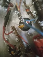
I'm not sure what kind of Diode this is ? 1960 or 1961 years , maybe a zenor or tunnel ? It's got positive 158 vac in on one side and 6 volts out on the other side and no negative voltage. It's on The negative Bias circuit on Two 6l6 GC , goes through two resistors into two 150 volt e caps installed backwards with the positives grounded and it goes out to pins 5 on The 6l6 tubes. I've been trying to look it up but I can't find anything like it . Maybe someone knows what it is or something else I can use in it's place ?
Attachments
Could possibly be selenium. Either way it's a critical component and I would replace it with a 1N4007 diode. Are there any bias adjustment pots?

There's No bias adjustment pot or pots but I was thinking about putting in two 5k pots with one for each tube. That is After I get it working again. After a lot of reading and research I'm thinking that I need A Zener type of Diode for voltage loss and regulation ? , I'm thinking about The 150 volts positive that's going in . Is that okay through a regular 1N4007 Diode in reverse Bias ? and is it going to regulate it at A -50 volts Bias ? . I'm thinking that it has to be a Zenor type in there to drop the voltage and regulate it , but it doesn't have to be because the resistance can do that also. It does have a cement 5 watt resistor to one of the e caps installed backwards. Maybe I am just overthinking it and I should just try putting The 1N4007 in there. It will either have negative voltage or something else will blow up but I will at least find out if the Diode is the problem or not. My biggest problem is that I don't have a wiring diagram for the thing and I can't find one. It's A 501273 Whirlizer amplifier. 1960 ish.
Voltage will likely be a bit higher (more negative) when the selenium one is replaced with a silicon one. Be sure that is not an issue with your replacement. In the case of a grid bias supply, the extra negative voltage could result in less quiescent current draw by the output stage, and that might need some adjustment. At least, any error will be in a safe, nondestructive direction, and it should be easy to correct. The 1N4007 diode will work well there otherwise.Could possibly be selenium. Either way it's a critical component and I would replace it with a 1N4007 diode. Are there any bias adjustment pots?
Seems odd that fixed bias would be used without any adjustments. Maybe the tubes were biased very conservatively to increase the lifespan?
It's got positive 158 vac in on one side and 6 volts out on the other side and no negative voltage.
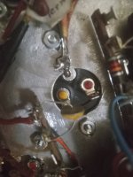
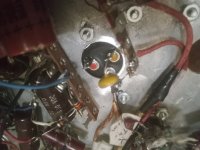
You are taking the voltage readings with the tubes out, yes? Is the 158v AC being read with a meter to chassis ground, or with a scope telling you peak-peak voltage? 158V of bias supply is really high for a 6L6 amp, assuming push-pull mono, yes? Does it branch to any other components to feed the driver from the ?? rectifier?? A top-side shot of the mystery component could help.
Last edited:
Using a Fluke meter and the 6l6 tubes are both out but the rectifier tube A 5U4GB is in. I think that they either used a Zenor type diode to lower the voltage or it's resistance and 1/2 of the splitter tube. I haven't been able to find a wiring diagram for the amplifier but I can see some of it.
Unlikely it’s a zener. Nobody ever regulated bias voltage. If you’re really curious you could disconnect one end and use the diode test feature to measure the forward voltage. That will indicate the material.
You have a Variac? An indispensable piece of test gear when working on amplifiers. Why? In this case, you can just replace the diode, but then bring up the AC to the connected amp slowly using the Variac dial. Observe the negative bias voltage as you do this - is it starting to creep up in DC value, say, as the AC input goes from 20 VAC to 35? When you're confident it is increasing negatively with AC line input, then you can swing the control out to 110.Maybe I am just overthinking it and I should just try putting The 1N4007 in there. It will either have negative voltage or something else will blow up but I will at least find out if the Diode is the problem or not.
Versus just plugging to the mains, hitting the power switch.
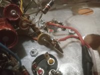
If I had to bet, I'd call that a ''modern'' selenium diode, low current type, single cell. Nothing special. Now, the issue with the small (+) voltage where there should be (-) bias voltage could indicate that a coupling cap going from driver to 6L6 grid is leaking high plate voltage and overriding the bias voltage. The final bias voltage of the 6L6 would be -20 to -30v but a leaking coupling cap could send that much (+)voltage down the bias circuit. That is if the circuit is similsr to most. Just an presumption. Keep working with the 6L6 tubes pulled and lift one leg of the mystery diode, then check for (+) voltage on the grid pin that shouldn't be there.Diode pictures
Last edited:
Selenium Diodes were very common when I still had hair & most of my teeth.
IBM used large Selenium FW stacks in some of their relay logic data crunching equipment when I worked there (1954) in outside service.
There were quite a few 25L6's used, the metal kind as relay & solenoid drivers, running at about 200V DC. That was in collating machines
During preventative maintenance many were discarded, I kept some that later worked well in several PP 25L6 amps I built.
I ran many forward drop tests on Selenium devices in 2017, all plotted on MS XL.
To put those on DIY they need to be converted to JPGs. Maybe tonite.
In ordinary rectifier service they are rated at only 25VAC per disc. PIV is very limited.
You could just as well lift one end of the coupling cap and see if the (-) bias voltage comes back. That would be my choice because most cases is a bad coupler.
I disconnected the grounds and the voltage into the Diode dropped from 158 vac to 128 vac and coming out from the Diode it went up from 6 vac to 99 vac , but it is still positive voltage and not negative voltage, Isn't it the two backwards installed e caps being fed By the diode leakage That together make the voltage go negative ? Or Am I misunderstanding something about how it works ?
I replaced the chassis with a new one and I could have missed a resistor to ground By mistake. It was a pretty complicated thing coming out of A Whulitzer Organ. I had to decide what to keep and get rid of. I'm also going to rebuild it with A Sunn Model T pre amp section. So basically I was just going to use The power and output section from the Organ.
I disconnected the grounds and the voltage into the Diode dropped from 158 vac to 128 vac and coming out from the Diode it went up from 6 vac to 99 vac , but it is still positive voltage and not negative voltage, Isn't it the two backwards installed e caps being fed By the diode leakage That together make the voltage go negative ? Or Am I misunderstanding something about how it works ?
If the mystery component is a rectifier, the polarity of the voltage out depends on the its installed direction. The output will be a pulsating - - - - - - DC, positive or negative. Half-wave. The meter needs to be set to DC but it won't be a recognizable level without filtering. During the chassis swap, was it removed, possibly replaced backward? Was the power transformer removed, possibly getting the bias tap lead swapped with one of the HV leads? At this point, without a sketch of the circuit and some other pertinant voltage checks, it's going to be tough to sort this issue out. If the 158v AC is actually coming from one of HV legs, then it will be going through a voltage divider and dropping circuit after the rectifier. That needs to be drawn out if it exists to make sense of the bias supply circuit. Is this a simple push-pull, (2) 6L6 mono amp? What is the unloaded B+ at the first filter? Is it a cap or is it choke, first?
On The DCV Scale I have Negative - 26.3 and Negative - 26.4 VDC of Negative Bias Now on both pins 5 and I regrounded the 3 e caps and it stayed the same. So I'm guessing that I was checking it wrong using The AC scale instead of on The DC scale. My mistake. That voltage - 26vdc seems a little bit low to Me for 400 volts Plate but it might drop down some to 350 under A load . I was thinking about changing the diode to a modern 1N4007 to raise it up little and putting two 5 K pots for a Bias adjustments one for each tube . It has 3 E Caps in the Bias section a 50@50vdc, 50@150 vdc and a 16@150 vdc right now. I would like to have two separate bias pots, it has none right now.
- Home
- Amplifiers
- Tubes / Valves
- Tube Amplifier negative Bias Diode type ?