I'm showing 548 VDC from The rectifier PIN 2 to the capacitor with the New Can grounded without A load of Any kind with the 6l6 tubes out. I was wrong saying that it was At 400 volts.
An amp I have looks like this, power supply wise -

You can see for the -24V section, it has a capacitor from the secondary HV winding, then a resistor divider, then the diode, then I assume a "bleed" resistor, then the cap right at the output.
If you can draw what you have in a similar way, it's better - well - as was said above "without a sketch of the circuit and some other pertinant voltage checks, it's going to be tough to sort this issue out."
Hope this helps,

I'm showing 548 VDC from The rectifier PIN 2 to the capacitor with the New Can grounded without A load of Any kind with the 6l6 tubes out. I was wrong saying that it was At 400 volts.
OK, those numbers make sense. High line voltage and no loads make sense. The bias voltage is within the right range so you're looking safe to load it up. Ground the signal input with some shorted RCA cables, have a go. I'd meter the B+ with some clip leads to the probes while you bring it up and see how high it goes and the time to drop back to normal run voltage. Normal checks.
There's a bunch of Whurly schematics here http://4tubes.com/2-SCHEMATICS/Music-amps/Wurlitzer/
I clicked a few at random, but none have the diode - all the 6L6 circuits are cathode current biased.
There's a pay for - couple bucks - whurly schematic site here https://thecodemachine.co.uk/Schematics/Search.php?manuf=Wurlitzer
Again, nothing corresponds to your amp model number. They must index by the unit it came out of...
Here's a homemade writing diagram of the Bias section from The PT to the grounds to the tubes.
Attachments

Last edited:
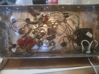
How about a photo of the whole underside of the chassis - clear and big as you can make it and still post here.Here's a homemade writing diagram of the Bias section from The PT to the grounds to the tubes.
It's not all together yet I'm waiting for A bunch of parts, Let me finish putting it together and then I will take another voltage reading and some pictures. But here's a few pictures of the project. Thanks for All of you helping me figure out what Was going on with The negative Bias. It's a big relief knowing that it is working properly. Now I can keep wiring things up. I'm a little bit rusty been a Few years since I did this. Thanks Again !
Attachments
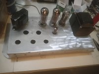
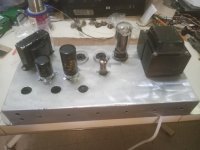
OK I see what you did there - I was somehow assuming the original chassis / wiring! Nice project.
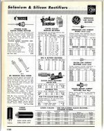
Page from a 1960 Catalogue of electronic parts covers Silicon, Germanium & Selenium rectifiers & Diodes available in 1960.
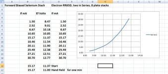
A Sarkes-Tarzian 700 single Disc Selenium Diode showing forward Bias drop on an XL plot I did several years ago.
The curve fits well with Square Law, typical of solid state diodes.
And a small multi disc diode for use in biasing. I used two each of these in a pair of PP UL 6L6GC amps I built around 1960.
The biasing circuit in those looked a bit like here on p22. THE HV rectifiers are 5AR4s.👍
Attachments


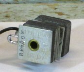
I'm wondering if this mystery rectifier is some form of a copper disc rectifier with leads attached and dip cased? Probably a short lived type if so.
The 5AR4 are pretty expensive Rectifiers in Mullard, I have one in My Bogen DB230A in my home studio. The 5U4 GB have a 550 Volt rating higher than the other 5U4 G 's . To me A 90 dollar plus difference in price is enough for me to say I'll pass on The 5AR4 tubes. They have one that's in-between A 5Y3 and 5U4 also but I can't remember the number. If I happened to run across a cheap 5AR4 Mullard I would pick it up but I can't really justify paying 100 dollars for a rectifier tube. Especially if The 5U4 GB can do the job. Now if I was out hammering the amp At full volume every night I would probably want A 5AR4 Mullard in it. But at moderate volume I probably won't even see enough sag to bother me.
Last edited:
In 1960 all these prized tubes of today were cheap. So we used boxes of some kinds,The 5AR4 are pretty expensive Rectifiers in Mullard
mainly high purveyance (5687, 7119, 6DQ5.............) for building test circuits for the research
we were involved in.
Your circuit may be using the same -ve bias circuit I used, it uses 2 diodes.
The loading on the PT is symmetrical, current is pulled on both halve of the AC supply.
So no DC offset of the magnetic flux in the PT as in the other circuits.
I see in my very olde schematic of the PS I've used 1N547 Si Diodes, probably since
there were plenty in the lab. The 1N547 diode was MIL Grade in that time.
I'm thinking the original selenium stack is still here in my stash.
Attachments

SS Stuff wasnt exactly cheap then. $17 / $27? As a cheap 3 year old, I'd have stuck with the tube. Imaging today paying $180 / $285 for a pair of enclosed diodes with a plug on it. How'd you afford building anything back then?Page from a 1960 Catalogue
As a youngster, you wanted something, cloth, radio, anything, you, your dad or mom, you DIY using chunk left over after the war.How'd you afford building anything back then?
The first transistor, a funny looking S&H (Siemens and Halske) was a weeks salary for me.
For the price of a 1/2W resistor i could have got a meal at a restaurant, a 15" inch JBL chassis would have been more than my total salary from the first 2 year i went to work.
It is nowdays for most folks totally unimaginable how things where back then.
Especially unimaginable for americans, my first month salary as a 15 year old was the equivalent of 7.20USD a month, working 45h a week (normal folks kids where expected to go to work at age 14, i was underweigth so i started school a year later than normal). 4 years later my salary triplet to almost 30USD and a year later sixfold, wow i finally made it and could afford to eat AND buy some stuff.
Last edited:
I went to work for Philips in 1963 for the stately salary of 3200 Dutch Guilders a year.
But at that time the exchange rate was 10 Guilders for 1 USD, so it came out to a salary of $ 320 per year.
But I did feel pretty rich, I had it better than most of my friends.
You have to look at it in the context of that time, or look at how much it would be in this time, otherwise the comparison doesn't tell you anything.
1 USD in 1963 would be 10.3 USD in todays money.
Jan
Even not considering the cost…. Having to use a stud mount rectifier just to get to an amp and a half? Crazy.
Gimmee my 1N5408, and step on it!
Gimmee my 1N5408, and step on it!
There seems to be an error in the drawing regarding the wiring of the 47k resistor.Here's a homemade writing diagram of the Bias section from The PT to the grounds to the tubes.
As shown, both the 47k as well as the 16µ cap would be useless.
The yellow diode is an International Rectifier 'Tri-sealed' model. I have one with IR marking and model 2E4, which IR catalogs from circa 1962 indicate are a 400V PIV of abt 0.25A silicon rating, and still being sold on ebay !
- Home
- Amplifiers
- Tubes / Valves
- Tube Amplifier negative Bias Diode type ?