Very sought after American High-End DAC, that normally is sold out because they are not able to deliver to the high demand ... And this one has been further
upgraded in 2 important areas (Analog output and PSU).
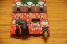
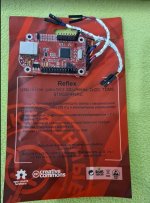
As the name suggests this is the newest model with an AKM 4483S DAC chip, and it is about 3 months old.
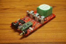
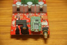
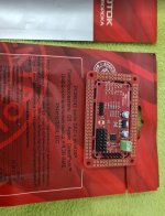
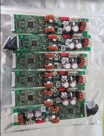
It is default delivered with OPA1656 op-amps in sockets in the analog outputs. They sound good, but not nearly as good as Sparkos discrete SS2590 Pro opamps,
that in mine and many others opinion are the best op-amps on the market. The SS2590 type are originally developed for expensive studio equipment, but Sparkos
delivers adapters, so that they can be installed in 8-pin DIP sockets, and therefore also can be used in consumer equipment. But be aware that Geshelli do
NOT
deliver these types from the factory. They only deliver the cheaper model SS3602 - so this is a unique offering.
As it is configured right now, it is only the RCA outputs that are running, because I have uninstalled the op-amps for the balanced outputs. But they can of course
be re-installed, if necessary.
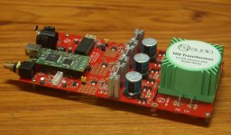
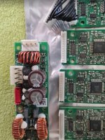
The Sparkos SS2590 op-amps gave a large quality improvement, and the next improvement appeared by installing a powerful and noiseless linear power supply.
So if you check out videos on YT, that generally are super positive, remember to add those 2 important upgrades to the evaluation.
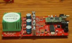
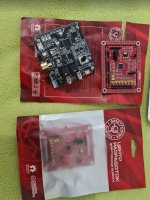
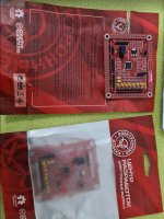
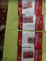
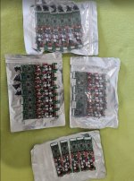
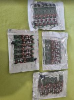
The DAC will be delivered in original packaging, with the upgraded PSU, and the standard PSU and 2 OPA1656 for the balanced outputs.
White alu housing with see thru plexi front and back plates. Measures: DAC: H5 x W16 x D12 cm., PSU: H5,5 x W10 x D21 cm.
The switch on the cable is installed because the linear PSU starts very slowly, and the DAC will not accept that, but will go into failure mode. But that is fixed with this switch.
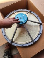
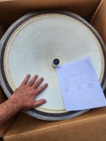
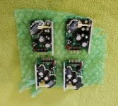
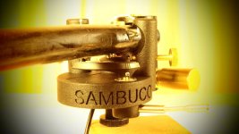
The pictures might not be exceptional, but the DAC is
🙂.
It can be sold for Euro 350 with the original OPA1656 op-amps installed in i both RCA and XLR outputs, but I recommend it with the SS2590 for Euro 470. It can be sent inside
the EU with GLS for Euro 30 - contact me for pricing outside EU. Payment could be PayPal
to a friend, or bank transfer.


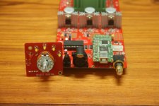
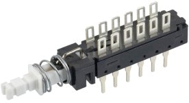
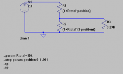
 I've included a photo of the backside of the potentiometer. I really hope anyone can help me with this


