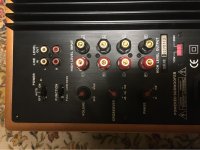
Upgrading Vacuum State FVP FVP-5 Tube Line Stage to FVP-6
Please note, the FVP-6A and FVP-6B line stage schematics are (C) Copyright Joe Rasmussen & Vacuum State and
only single user license is granted.
The original FVP5 schematics also had shared copyright, but SVP-1 and SVP-2 are Copyright Vacuum State. Their schematics have similarities but will not be shown here as I consider them belong to Vacuum State which will still make them. So understandably, I am not comfortable in posting them.
Here for DIY purposes, we shall show two variations called FVP-6A and FVP-6B:
What makes them new is that they are based on the
12AT7A/ECC81 tube instead of 6DJ8/6922/ECC88 tube. Down here in Australia a number of FVP users were persuaded on my recommendation to change away from the ECC88 tube to the greatly underrated "T7" tube in the line stage (the ECC88 remained the same in the phono stage). Nobody regretted it and reported they liked what they heard. There is something about the "T7" tube, it does not try to be high or low gain or mu or anything special. It seems to hit a sweet spot of its own. Like it is not trying to do anything hard.
OUR PROBLEM? CONTROLLING THE GAIN!
This what the early FVP5 did to control the gain, a resistor was added to draw additional current and it looked like this:
This is a crude way of lowering the gain to something manageable. In effect the 25K and 47K look in parallel and also brings the Anode voltage down to where we need it to be. BUT...we want to avoid using this resistor and there are two ways of doing it as well as being able to set the gain where we want it.
The two methods both involve using a current sources.
The reason for being two variations, FVP-6A and FVP-6B, it has to to with FVP-6A requiring an added negative voltage (-15V), and FVP-6B does not.
Both methods should work well. The "B" variant is simpler as it does not need an added negative power supply.
The schematics as shown uses +250V, but it could be used with as low as +210V, but with lower voltage the circuit adjustments in the circuit become more critical.
Gain is aimed to be around 15dB approx (5-6x) but it can be trimmed a bit lower. For sure these things can be discussed as we go along. We gain discuss what is needed to do to get the gain you want. How that can be done, this we can discuss as we go along.
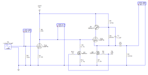
Here is the
FVP-6A schematic:
Some simple modeling:
(100mV in and 560mV out.)
What you use as a current source is up to you. Dial in enough current to get you approximately +130V on the Anode of the input gain tube. This also provides a good bias voltage for the buffer stage "Super Linear Cathode Follower" or SLCF for short. This is the key voltage in the circuit.
How you get the +250V is up to you. You can use a SuperReg for sure, but whatever you use, note that it will have an effect on the result, the sound. Power supplies always does.
The
+15V comes from the filament supply. The "T7" filaments are wired in +12.6V (series) and are fed with an inline 15 Ohm 1W resistor with will drop down the voltage by a couple of volts. This also creates a slower start when the filaments are cold and good for long-term life.
The
-15V needs to be a dedicated supply and it to needs to be regulated. The R9 resistor value
"???" is adjusted, so that +130V appears on the Anode of the "T7" gain stage. The R9 value here should not be copied, the correct value needs to be found.
Some may have noted that the SLCF uses a Darlington instead of a HexFet IRF710 used in the Vacuum State circuit. This is to avoid this 47K resistor:
This resistor should ideally be eliminated. The 47K was required because the HexFet's non-linear capacitance could affect the performance. Allen decided to add enough resistance to prevent it from misbehaving. Of course, the SVP variants used an actual tube and that meant he could get rid of that 47K. But here we don't have that option. Hence the idea was developed to used a Darlington with a gain of 500 or higher. The MPSA29 should do the job nicely, but will need a 33-47V Zener to protect it.
The R4 470K or 560K needs to be adjust so that the voltage drop caused by the Darlington is 15-20V. Hence the Anode of the follower will see around around +230V to +235V.
How you come up with the +250V and -15V respectively, we can have a discussion about that.
Next is the
FVP-6B Schematic:
Some simple modeling:
(100mV in and 600mV out, gain = 6)
Now we have done away with the extra negative power supply. That is quite a few components eliminated.
Note: Only four additional components, three resistors and one HexFet, typical an IRF710 or IRF820, per channel.
Note that Anode load value is lower and so it the Cathode resistor value, compared the FVP-6A. In this circuit, it is R11 that is adjusted to give the same +130V.
This current source effectively takes the place of the 47K resistor that we might other wise have used. But a current source presents a hugely larger impedance, indeed the ideal current source is infinite.
The FVP-6B does draw more current from the +250V power supply than the FVP-6A.
Please note re the Buffer or SLCF, it does not have the same output grunt as the ECC88 version. But it is quite adequate for our purposes. We are mainly concerned about the sound.
So there you are. I am sure that there will be lots to discuss, but much of it should be obvious to seasoned DIY'ers and also for them to be helpful to others.
Let the building commence...