F5m kit

Presenting the documentation for the F5m appearing shortly in the store.

The Essentials kit consists of the Jfets and Mosfets plus two channels of pc board and 1 power supply pc board.

The Completion kit is everything else except chassis, power transformer, rear panel connectors/switch/ac inlet.

The kit is designed around several chassis available in the store, but is fairly agnostic.

Attached is the article I wrote for this project, and this is the support thread.

:snail:

2/11/2024 After testing by member 6L6, I revised the power supply layout and made an additional
note about the power supply thermistors with higher output stage biasing. The revised article is labeled
R1, and both are attached below.


Update Alert: It turns out that the insulators we bought were not very insular. Not a disaster in general
but a problem if your heat sinks are bare metal. Different pads are available for this.

See the details in post 1,003 of this thread.

Also note 4/21/2024 revision of the power supply board. :snail:


EDIT: Build Guide here - https://guides.diyaudio.com/Guide/F5M+Amplifier/29?lang=en

Attachments

BOSS CE-4800D Parts or (Schematic)?

image.jpg
image.jpg
image.jpg
Guys greetings, I have a power to repair, customer says it was attempted after it first died but it seems they attempted the repair. However the parts doesn’t seems to be appropriate based on their arrangement. Can someone suggest power supply FETs and audio output FETs or a full or partial schematic? They had IRF540N in the PS and a mixture of P75N05 mixed batch in the output.

Wayne's BA 2018 linestage

Any thoughts or comments on Wayne's linestage presented at BA 2018?

It looks like an economical high performance design with a couple of nice options (like a beefier output if needed)

I'm a terrible designer and a slow builder - I think we wound be interested in hearing if there are any experiences or opinions yet.

Thanks Wayne!

YouTube

Attachments

  • wayne.JPG
    wayne.JPG
    51.9 KB · Views: 27,322

My presentation

Hello everyone,

My name is Marc and I joined this forum to find help with building my ESP P101 amplifier.

I am interested in many things, particularly electronics for audio applications, but not exclusively.

I have designed and built a 3D printer, integrated Tuya into fans, repaired numerous devices, electrified bicycles, and designed and built my own high-powered electric bike.

In the field of electronics, I am an amateur with very limited knowledge, but I am quite skilled at soldering and am fairly well equipped (soldering station, desoldering station, spot welder, LCR/battery meter, multimeter, digital oscilloscope).

Thank you in advance to everyone for your future help.

Electrocompaniet EC-3 and ECMC-1, schematics wanted

Dear all,
I am looking for schematics from mentioned Preamp and Step-up board. Main pre is working OK, with Line inputs, but phono one have problem. Since ECMC-1 is a step-up board, I cannot check it either. I contacted mother company but they told me it is not in their policy to share such service information...
I would appreciate if someone has drawings (is OK in scan or photo) to help me out to repair it.
Best regards,

John

Jeff Rowland Coherence 1 - Schematic for the Modules wanted

This Thread exist already and is closed:
Jeff Rowland Coherence One Schematic - diyAudio

I want to have the schematics of this discrete jFET operational amplifiers:
1) Phono Amp Low Level
2) Phono Amp High Level
3) LINE AMP INVERTING
4) Line Amp NON inverting

Who can help?
The modules are similar to those from JC-2 (John Curl, Mark Levinson)
JC-2(220V仕様) Mark Levinson - HiFi-Do McIntosh/JBL/audio-technica/Jeff Rowland/Accuphase
Schematic of the main- and front board/power supply are in post #71 (page 8) under
Jeff Rowland Coherence 1 - Schematic for the Modules wanted

Attachments

  • Rowland Research Coherence 1 Phono low level module botton.JPG
    Rowland Research Coherence 1 Phono low level module botton.JPG
    22.4 KB · Views: 3,462
  • Rowland Research Coherence 1 Phono low level module.JPG
    Rowland Research Coherence 1 Phono low level module.JPG
    88.1 KB · Views: 3,392

System Pictures & Description

I invite everyone to post a picture and description of their systems. Comments are welcome!
(Mods: It may be useful to make this thread sticky or move its location)

My system was put together on a grad student's budget - i.e. next to nothing. I built the speakers using vintage Alnico drivers from Dave aka planet10. I built the stands very cheaply from plumbing parts. Currently, I'm using two Sansui amps; one for the speakers and a second for the stereo subs seen under the desk. I'm currently gathering parts for a Mini-Aleph that will replace the Sansui driving the main speakers.

The sources are a Panasonic CD player, a belt-driven JVC turntable, and 10 GB of MP3s from my computer. I also have a Rega Planar2, but it's currently being used in the HT system. The preamp uses a single +24V power supply to run the 12AE6 space-charge triodes and heaters as well as the TI BUF634 buffers.

Cheers,
Eric


Complete system:
An externally hosted image should be here but it was not working when we last tested it.


Component rack:
An externally hosted image should be here but it was not working when we last tested it.


Pete Millett Hybrid preamp/headphone amp:
An externally hosted image should be here but it was not working when we last tested it.


Component rack, stylized picture :
An externally hosted image should be here but it was not working when we last tested it.

Adaptor PCB 2SK2145GR as 2SK170BL Substitute

There have been endless discussions about 2SK170BL replacement.
I have already published data indicating that 2x209GR in parallel would be a good replacement in all respects.
https://www.diyaudio.com/forums/pas...source-follower-applications.html#post5582425

Of course you can also use a single 2SK2145GR, which is in principle 2x 2SK209GR.
They are not guarantee to be a match pair, and from experience some 10% are poorly matched.
So the best is to measure the Idss of each JFET and select only the good ones.
But for those who just want to save money and don't care about performance,
no one will stop you from using the 2SK2145GR without any selection.

Here are the Gerber files of a small 5x5mm conversion PCB.
Both size and pin assignment correspond to the 2SK170BL.
Plenty avaiable at Mouser, etc.
What more do you want ....

🙂


Cheers,
Patrick

.

Attachments

C/E/X PA Flat to 30 (FT30) PA TH Awesomeness

This thread is a continuation of woody1's thread (flat to 40Hz) which can be found here: http://www.diyaudio.com/forums/subwoofers/170749-15-tapped-horn-rcf.html

Epa, Xoc1 and others have been contributing their time and effort in attempt to help me reach my goal: Flat to 30Hz with as much clean output as possible - XTRA points for breaking physics and keeping it small. Heh.

We have found 15" drivers are limited by xmax far before maximum power is reached.

Here's where we left off:

Post 73 (Epa) @ 2.83V
30Hz = 95.28 dB
40Hz = 98.58 dB
3.3 dB difference

cres2.jpg


Post 98 (Xoc1) @ 2.83V
30Hz = 96.17 dB
40Hz = 100.74dB
4.57 dB difference, so step from 30 to 40 Hz is 1.27 dB more...

197479d1290430180-15-tapped-horn-rcf-bms18n850v2-6-fold-th-1.jpg

197480d1290430180-15-tapped-horn-rcf-bms18n850v2-6-fold-th-2.jpg


My REAL 6 Fold mod (I meant to post) @ 2.83V
30Hz = 98.29
40Hz = 98.48
0.19 dB difference, so step from 30 to 40Hz is 4.38 dB less AND 2.12 dB more output at 30Hz

18N850v2REAL6foldmod690WInputParameters.jpg

18N850v2REAL6foldmod690WSPLResponse.jpg

18N850v2REAL6foldmod690WDiaphragmDisplacement.jpg

18N850v2REAL6foldmod690WSchematicDiagram.jpg


What's your take on this version?


Post 98 is more efficient at both frequencies as would be expected as it is bigger. External is 600 litres compared to 397 for post 73.
Biggest misgiving I have about the post 73 design is the small S3 dimension.
At 1236 this is about the same size as SD. You can see how tight the mouth is positioned to the rear of the driver. This would require care and adjustment to make it work due to the driver seriously restricting the mouth. I suppose an access panel would be needed to actually get the driver in the box!😱

restriction is not to bad because of the neodinium magnet.
ff%20iets.jpg

i designed the post 73 th for the use in a cardroid sub aray.
this is why its symetric.
i like xco1 model 2,its a easier bild but for me a little to big.

i wil work this weekend on it to give you al the details😉
meanwile here are some designs,most of them are posted here.to make your choice more diffecult😛
kies.jpg

Must they (post 73) be used in a cardioid sub array? Will I/we loose any performance if they're not?


yes the idea was to make the front parts removeble 🙂
(Referring to post 73)

ok lets make it 15mm.i think 18 is a bit over the top.
horizontal there are only small spaces ,and vertical wil do some bracing in the middle.
front wil be removeble in one piece.
it might be a good idee to send you the dwg,dxf file when im finnished.
then you can make a 1 on 1 print on A0 paper(it fits)in the copy store.
cost about 4 euro here on this side of the pond🙂

justin ,we need to make a new topic,because this has no longer anything to do with woodys design ,:nownow:

Welcome 🙂


Any others: feel free to post your design if you believe it betters any of these and fits the goal posted above. Many thanks!

Justin

Is this okay (Ultimax 2-8” vented)

Anything ‘wrong’ with this?

Maybe there’s a ‘better’ use of chamber or port size/shape to arrive at a similar Fb?

Seems like I can really drag a high QTS driver down low regardless of its Fs in some of these big vented boxes? ( Fs 46 hz , Qts 0.75)

Attachments

  • att.n4qC9ZGlGMFXCEls01o4vOkHMREocRhy8G_9L26uRwc.jpeg
    att.n4qC9ZGlGMFXCEls01o4vOkHMREocRhy8G_9L26uRwc.jpeg
    50.8 KB · Views: 157
  • att.dbpKeh26qQFV64I9gsZUBuyaf-MZWlVuOKCaOfdYm2Y.jpeg
    att.dbpKeh26qQFV64I9gsZUBuyaf-MZWlVuOKCaOfdYm2Y.jpeg
    43.7 KB · Views: 153
  • IMG_3961.png
    IMG_3961.png
    614.5 KB · Views: 143
  • IMG_3960.png
    IMG_3960.png
    625.3 KB · Views: 147
  • att.5q8r6F4Hp-TiPgnkvonNWRk8hiAk7vQGEUxi1zM97zY.jpeg
    att.5q8r6F4Hp-TiPgnkvonNWRk8hiAk7vQGEUxi1zM97zY.jpeg
    59 KB · Views: 153

Hi there forum members, my company is hiring!

Renaissance (Scotland) Ltd are hiring service staff. We are currently looking to recruit a hifi service & repair technician on either a full or part time basis. The job location is in Edinburgh.

Please see the details on LinkedIn or PM for full details

https://www.linkedin.com/jobs/view/4237706192/

https://www.renaissanceaudio.co.uk/

Many thanks for taking the time to read this post

John
  • Like
Reactions: analog_sa

Learning assistance

Hello,
I wonder if someone could suggest a good source of information, either in print form or online is fine, for understanding a particular negative feedback circuit as it applies to shaping an EQ response. In other words I would like to learn how it functions (I have a good idea of the basics) and what the mathematics are for determining component values and how to change them to achieve different requirements. This is the circuit I'm interested in:
Screen Shot 2025-06-08 at 11.18.51 AM.png

CamillaDSP - Cross-platform IIR and FIR engine for crossovers, room correction etc

I would like to announce CamillaDSP, a general purpose tool for routing and filtering sound. It can be used for example for building crossovers for active speakers, or for performing room correction.

You can find the source code here: GitHub - HEnquist/camilladsp

The documentation for all published versions can be found here: CamillaDSP

There is a second repository for configuration help here: GitHub - HEnquist/camilladsp-config: Help for setting up CamillaDSP, example config files etc

Quick summary
  • For Linux, macOS and Windows
  • Written in Rust
  • IIR filters (BiQuad)
  • FIR filters (Convolution via FFT)
  • Built-in sample rate converter
  • Filters can be chained freely
  • Flexible routing
  • Alsa, PulseAudio, Wasapi, CoreAudio, File and stdio input/output
  • Simple YAML configuration
  • All calculations done with 64-bit floats

I have been using BruteFIR for crossovers for quite some time, but there were two main things I wanted to improve upon. Firstly BruteFIR only supports FIR filters, and I wanted the ability to also use BiQuad without having to make an overly complicated setup. Secondly when BruteFIR encounters a buffer underrun it always exits with a "broken pipe" error instead of just trying again. This can get somewhat annoying. I also thought that the BruteFIR configuration is unnessecarily complicated.
I have also been using the excellent tool EqualizerAPO that does all I want, but it's for Windows only.

When using Alsa for both input and output, CamillaDSP can work almost as a drop-in replacement for BruteFIR. I run a 2048 tap stereo 2-way crossover at 44.1kHz, and this consumes less than 2% of a single cpu core on my HTPC (dual core Intel Skylake).

To help with configuration CamillaDSP checks the configuration and tries to give helpful error messages when there is a problem. In addition there is a Python script to visualize the whole pipeline from a config file.

Sample output:
pipeline.png


To try it, download a pre-built binary for your system from the "Releases" page:. Click "Assets" to view the available files.

Instead of using a pre-built binary it can also be built from source. The "Cargo" tool makes this very easy as it will download and compile all dependencies automatically. See more instructions in the README.

Universal Tiger

In the late 70s, my friends and I assembled 3 "Universal Tiger" amplifiers degigned by Dan Mayer and sold by SWTPC.

After a couple months of operation, they all blew their output transisters. Recently I was browsing Dr. Leach's site and read his comments regarding the design."These amplifiers were very unstable, causing them to oscillate, overheat, and blow tweeters."

I find all this strange as, at the time, the Hirsch-Houck Labs gave the amplifier very high marks for sound quality and stability

Have you experts ever looked at the schematic to determine what could have caused the problem and how it can be resolved?

I would appreciate your comments.

I attach a copy of the schematic.

Attachments

  • universal tiger.gif
    universal tiger.gif
    33.8 KB · Views: 7,020

For Sale Gilmore Dynalo PCB kits with matched transistors

Two Dynalo kits left with genuine well matched transistors available after getting parts for my own needs.

Included in Dynalo kits:
2 x Dynalo amp boards
1 x Golden Reference supply board
2 x THAT340 converter PCBs for Toshiba 2SJ74 + 2SK170BL JFETs (other adapters available for LSK489 & LSJ689, see pics)
32 NPN & PNP tightly matched MPSW56 & MPSW06 output transistors. (16 per board)
12 x well matched VAS/CSS transistors (6 per board)

Two Dynalo kits left
£50 GBP + shipping - EU should be around £7 tracked, USA £11 tracked

Attachments

  • IMG_0286.JPG
    IMG_0286.JPG
    967.2 KB · Views: 664
  • IMG_0289.JPG
    IMG_0289.JPG
    931.1 KB · Views: 537
  • IMG_0292.JPG
    IMG_0292.JPG
    734 KB · Views: 497
  • IMG_0297.JPG
    IMG_0297.JPG
    746.4 KB · Views: 525
  • IMG_0293.JPG
    IMG_0293.JPG
    643.1 KB · Views: 596
  • IMG_0298.JPG
    IMG_0298.JPG
    863.1 KB · Views: 651
  • Like
Reactions: Pars and itsikhefez

T.H.E. Show SoCal 2025 Jun 6 - 8 - Sunset Beach

T.H.E. Show SoCal 2024
https://www.theshownow.com/
The Hilton Orange County Costa Mesa, CA - Sunset Beach Room (beside Newport Beach Room)


To find out why Marc gave me pretty high compliment about my system, I would like to invite you to visit us (Seal Beach Room)
https://parttimeaudiophile.com/2023/05/22/phasemation-yukiseimitsu-wolf-von-langa-munich-2023/?amp
"however, had a unique soundstage that reminded me of the first time I heard a VK Music system featuring Sunvalley amplification, AER speakers and a Sparkler Audio CD player. It’s a sound that pulls you inward until you’re immersed in an otherworldly and vaguely spherical image that informs you of everything that’s happening within the music."


For Sale complete F6

Complete F6, built spring of 2021.
The amp is incredibly well built, with overspeced components throughout. This F6 features a giant 400VA power transformer, complemented with a built in slow start warm up circuit.

Summary of the nominal specifications:
  • Distortion @ 1 watt 0.05%
  • Input Impedance 100 Kohm
  • Gain 14 dB (5x)
  • Input Sensitivity (1 watt) 0.57 V
  • Input Sensitivity (max output) 2.83 V
  • Damping Factor 16
  • Output power 8 ohms 25 watts @ 1% THD, 1KHz
  • Output power 4 ohms 50 watts @ 1% THD, 1KHz
  • Frequency response - 3 dB @ 1 Hz, 50 KHz

Manual:
https://www.firstwatt.com/wp-content/uploads/2023/08/prod_f6_man.pdf

*** Due to size/weight I am unfortunately going to restrict this sale to local sales only (Toronto, GTA)
$1100 CAD ($800 USD)

Attachments

  • 1.jpg
    1.jpg
    526 KB · Views: 106
  • 2.jpg
    2.jpg
    799.6 KB · Views: 104
  • 3.jpg
    3.jpg
    606.6 KB · Views: 105
  • 4.jpg
    4.jpg
    391.3 KB · Views: 99
  • 5.jpg
    5.jpg
    574.6 KB · Views: 94

My Stasis 3 needs a service

Hello

I once owned a Threshold Stasis 3 and Fet One pair, which I loved, but had to sell due to financial difficulties.
This set worked well with my Ditton 66s, which I also had to sell along with the Threshold set.

I was able to buy my Ditton 66s again, 20 years later, but the Threshold set had long since been resold.
I started looking for a new set, but these devices are rare and still too expensive for me.
I was lucky to find a Stasis 3 and an NS10 separately, both in France.

The NS10 was 110V, so I easily switched it to 220V and replaced all the chemical capacitors. I'd still like to find a Fet One, but they are very rare, especially in Europe.

I haven't done anything on the Stasis 3 since I got it. I recently decided to replace the RCA sockets because the plugs don't hold well.
I knew this amp had been professionally repaired, but what I didn't know and didn't see was that the job hadn't been done very well: some wires were melted and the circuit boards were damaged.
At that moment, I regretted opening it!

The RCA cables had been replaced, but they were too stiff and had bent the leads of an MPSA42, making contact with each other. Luckily, these leads were already in contact on the circuit board, so it didn't change anything!

So I completely disassembled the amp to rewire it.
While cleaning the circuit boards, the leads of a 2SA1112 were cut off flush with the case. I was lucky here too, because since I listen very loudly, they could have broken from the vibrations.
So I was right to take it apart, without knowing it. I replaced the 2SA112 and 2SC2592 with MJE15033G and MJE15032G, which I had in stock.

I rewired it, changing all the ring terminals and lengthening the wires so I could keep it open without unwiring anything. I also changed the banana plugs.

I was very nervous about powering it up again. I first used a 100W bulb in series and measured the output voltage. There were 2x16V on the filter capacitors and over 100mV negative on the outputs.

I finally mustered the courage to connect it directly, and it didn't catch fire! The output offset is lower but still high: -48mV on one channel, -60mV on the other.
But, after a while, the offset increases on the channel that was at -48mV, going beyond -70mV after only a few minutes, while it decreases a little on the other channel to around -50mV.
The transformer is a bit noisy, I'd never noticed it before.

I noticed that it heats up much faster, and that the temperature seems higher than before.
Perhaps the fact that the MJE transistors have a much higher gain than the original ones means the quiescent current is higher?
I'll have to adjust the quiescent current potentiometers; it scares me.
I'll first open it up and measure the voltage across one of the emitter resistors on each channel to get the actual value of this current.

I would need to replace the two filter capacitors, but my finances do not allow me to do it at the moment, I will do it later, perhaps at the same time as replacing the two printed circuits of the input stage.

Here's some photos before my intervention:

20250525_164145.jpg
20250525_164214.jpg
20250525_164253.jpg
20250526_093401.jpg
20250526_093405.jpg
20250526_093414.jpg


After my intervention

20250531_123029.jpg
20250531_125447.jpg
20250531_190429.jpg

Spectral DMA 100 Help needed

Hi,I have a stripped Spectral DMA 100 amplifier,need help finding power supply specs for both driver and output.
I have a need to build power supplies as the chassis is missing both transformers……maybe use the chassis,I do have a Diyaudio 5U chassis new in the packing…I have been saving it for a new project,or,if the transformers needed can fit the original chassis,maybe use the Spectral case.
all outputs verified ok.
The boards appear to be prototypes,there is no serial number sticker on the back of the case….found at the Alameda Antique Fair,SanFrancisco in 2017…..
thanks,Dave Grady

Attachments

  • IMG_0859.jpeg
    IMG_0859.jpeg
    391.6 KB · Views: 399
  • IMG_0858.jpeg
    IMG_0858.jpeg
    526.3 KB · Views: 454
  • IMG_0860.jpeg
    IMG_0860.jpeg
    469.1 KB · Views: 409
  • IMG_0861.jpeg
    IMG_0861.jpeg
    448.1 KB · Views: 389
  • IMG_0862.jpeg
    IMG_0862.jpeg
    532 KB · Views: 354
  • IMG_0863.jpeg
    IMG_0863.jpeg
    502.5 KB · Views: 362
  • IMG_0864.jpeg
    IMG_0864.jpeg
    449.3 KB · Views: 352

Ulawatu Kit Speaker.Is it really tube amp friendly?

According to the data the Ulawatu kit speaker should be lowish powered tube amp [SET] friendly.
Specs say they do not dip below 5 ohms and are at least 92db/watt sensitivity.
Has anybody used them with amps like that?I have an Almarro 205 which is only about 2.5 watts and an Almarro 318B which is more like 12 watts.Also a vintage Mullard 520 push pull at about 25 watts.
It is for a second room which is 4.8m by 3.4m so a medium to small room.A good sounding room though.I had Dynaudio C5s in there but sold them.

https://www.google.com/url?sa=t&sou...QQFnoECBkQAQ&usg=AOvVaw2iZQ_i3HIkZDZ3VLEuiekF

DAC AD1862: Almost THT, I2S input, NOS, R-2R

Use this link for more details:
https://electrodac.blogspot.com/p/dac-ad1862-almost-tht-i2s-input-nos-r.html
Note: 8th pin on the I2S input header is missing connection with the GND (on some of my PCBs this pin is unconnected, if you are going to use it, solder it with the nearest GND pin on the header)


People who are selling brand new unused AD1862 or AD1865 chips:
I want to thank @Paddy Garcia for the whole happy DIY community. He did very honorable work: Group Buy #92 :worship:


Special tested DACs:
DAC702BH/CH (Glue logic - I2S data input) (result: audible digital noise on the output, not good for audio use)
DAC8811 (CPLD data input) (result: audible digital noise on the output, sound far away from very good audio, don't waste time and money on such DACs)
...

Attachments

  • diyAudio_AD1862_DAC_v1.3_uf.l_2021-06-10.zip
    diyAudio_AD1862_DAC_v1.3_uf.l_2021-06-10.zip
    692.2 KB · Views: 1,707
  • diyAudio_AD1862_DAC_v1.3_uf.l_Top.png
    diyAudio_AD1862_DAC_v1.3_uf.l_Top.png
    108.8 KB · Views: 6,982
  • diyAudio_AD1862_DAC_v1.3_uf.l_Schematic.jpg
    diyAudio_AD1862_DAC_v1.3_uf.l_Schematic.jpg
    403.5 KB · Views: 7,364
  • AD1862_BOM_v1.3.jpg
    AD1862_BOM_v1.3.jpg
    330.8 KB · Views: 6,752

Signalyst DSC1

The author of HQplayer Jussi Laako released design of this dac on Apr 18.
It's a pure DSD 1-bit 33-level dac with full support from HQplayer.
Signalyst
Anyone interested?

Interested in getting boards? http://www.diyaudio.com/forums/digital-line-level/254935-signalyst-dsc1-6.html#post4175377

Important grounding and gain modifications: http://www.diyaudio.com/forums/digital-line-level/254935-signalyst-dsc1-2.html#post4104608

Hello DIYaudio Community

Hello DIYaudio Community,

My name is James and I'm a new member. I've been an audio enthusiast for > 20 years, enjoying both listening to music and learning about the technology behind it. I particularly appreciate well-built amplifiers and line power systems etc...

Recently my Unico CDP has got problem somehow! In order to troubleshoot the CD player myself, I'm hoping to get a service manual or schematic diagram.

Before posting this request, I searched the forums extensively using terms like "Unico CDP schematic," "Unico CD service manual," and variations of the model name. Unfortunately, I haven't been able to find the specific documentation I need.

Would anyone in the community happen to have access to, or know where I might find, the schematic diagram or service manual for the Unico CDP CD player ? Any pointers, suggestions, or shared knowledge would be immensely appreciated.

I look forward to learning from and contributing to this knowledgeable community where possible.

Thank you in advance for your help and expertise!

Best regards,
Jamesckm

Attachments

  • 20250610_104010.jpg
    20250610_104010.jpg
    701.1 KB · Views: 34
  • Like
Reactions: lineup

Sample rate switcher for CamillaDSP

I have developed an automatic sample rate switcher for CamillaDSP.
Unlike gaudio_ctl, this tool is dedicated to updating the CamillaDSP configuration, so there is no need for external programs.
It also automatically reloads a valid configuration after the USB playback device has been unavailabe for a while (e.g. when you switch the input of your DAC from USB to S/P-DIF and then back to USB).
Details and software are available on github.

https://github.com/marcoevang/camilladsp-setrate

Another realization of Bob Cordell's THD Analyzer

Hi all,
I started the adventure to build Bob's THD Analyzer.
I made new PCB for my implementation.
They are: one for Sine Generator and Output Attenuator with the connector for the switch capacitors range board.
The cap sw PCB for Sine Gen, and Filter range (two equal for both).
One for Filter, Amp and Freq Detect.
One for Output Filter with connector for the Meter
One (little) for Meter circuits. Mount AD536AH for RMS conversion
One for Input Attenuator/Amplifier
I still have not decided how to switch the resistance of the frequency, probably Optofet or Photoresistors but they latter have serious problems of thermal drift.

....le first photos

Attachments

  • THD SINE PCB (Small).JPG
    THD SINE PCB (Small).JPG
    63.5 KB · Views: 2,730
  • CAP SW PCB (Small).JPG
    CAP SW PCB (Small).JPG
    62 KB · Views: 2,628
  • THD FILTER AMP FREQ DETECT PCB (Small).JPG
    THD FILTER AMP FREQ DETECT PCB (Small).JPG
    70.5 KB · Views: 2,609

For Sale Matched octet 2SJ74BL/2SK170BL

I’m dependent on matched Jfets for my amplifiers, so I have used otherwise idle time to measure, with PEAK DCA75, about 1500 pairs.

At my rate, those, combined with my untested stock, will see me well into the eighties, so I’m offering octets, four of each N and Ps, for €80, all inclusive.

Values between 6,5mA-10,5mA can be supplied.

Registered shipping, PP family and friends to EU citizens only. Postage outside EU is killing.

R

Attachments

  • IMG_1354.jpeg
    IMG_1354.jpeg
    526.1 KB · Views: 510
  • IMG_1353.jpeg
    IMG_1353.jpeg
    583.1 KB · Views: 513

Protecting BC1s

Having recently acquired a Sugden Headmaster and a Quad 909, I fitted new drivers - new supplied by Spendor in 1997 but never fitted. I am absolutely delighted with the way everything performs. However, I am concerned about overdriving the Spendors and want the main drivers to last.

So, I got to thinking about taking some of the power away from them with a supplementary woofer/mid-range unit. This led to reading as much as I could about various projects and one in particular was the modification to the B&W DM601 S3 cross over. I subsequently bought a pair from eBay, plus a few other bits - good quality and cheap.

However, the more I thought about, the more I realised - whilst it may keep me entertained, it is not an area where I am likely to produce successful results. So I came to the conclusion that I should leave the Spendors alone and go for creating/making a L.S. of my own.

I became intrigued with a full range speaker, vis a vis centred around Fostex units, in particular their FE208 E Sigma. This unit is recommended for Horn enclosures, but as an intermediary stage, want to use a conventional Ported Enclosure.

Fortuitously, a pair of CM7 crossovers arrived today, which are a joy - given the quality I got for peanuts.

The question is now however; before I lay out some serious cash on drivers - does anyone have any experience with Fostex units and the particular one I am interested in is FE208E Sigma. This is recommended for horn enclosures. However, this is going to be a two stage project. The intention is to couple this with a Monacor RBT - 95SR. It may well be it ends up with the Fostex T900A.

However, this is a serious project to keep me occupied through till spring so some serious advice is needed before splashing the cash.

Any help - no matter how trivial the contributor may feel it is, would be gratefully appreciated. - Kicking ideas around gets one closer to a solution, so everyone's contribution is valuable.

As a base line, ultimately I would like to go for a horn enclosure, so this limits the type of drivers I need to employ.

Bad news for Ripole sub builders :-(

The inexpensive 12" Peerless SLS woofers work really well in Ripoles. In fact; the SLS 12 is my all-time favorite $75 woofer.

I regret to report that the Peerless SLS 12 and XLS 12 woofers are no longer available at Parts Express without a 100 quantity min-buy. I called Parts Express about this and was told that the manufacturer (Tympany) imposed the 100-qty min-buy, not Part Express. Apparently; these woofers are being phased out but I don't see any comparable replacements for them on Tympany's website.

The discontinuance of these woofers seems non-sensical to me-- rather like Logitech discontinuing their Transporter streamer.

If anyone is interested in doing a group min-buy; count me in for ten.

For Sale Various STK

I have given shelter to these items long enough. It’s time our ways part.

Perfect stock for a small repair shop.

There are a few used ones. To the best of my knowledge they are fine.

No, I will not sell them individually, but I might entertain splitting I half.

I will include a few bonus items, names to be unmentioned.

€200, shipping to EU included.

Regards
R

Attachments

  • IMG_2527.jpeg
    IMG_2527.jpeg
    1.3 MB · Views: 94
  • IMG_2530.jpeg
    IMG_2530.jpeg
    1.1 MB · Views: 91
  • IMG_2529.jpeg
    IMG_2529.jpeg
    761.6 KB · Views: 84
  • IMG_2528.jpeg
    IMG_2528.jpeg
    927 KB · Views: 90

Chip Amp Photo Gallery

A lot of the other forums have a permanent photo gallery for projects, so why not the Chip Amp forum?

I will kick this off with my newly finished Chip Amp and let the moderators decide if this should be a permanent thread or not.

This is an LM3886 based Chip Amp using PCBs from www.chipamp.com.

The tranny is a Piltron 160VA 22V transformer with 15000uF caps and snubbers.

For a more laid back sound, I went with Carbon Film resistors.

The results really surprised me. The Chip Amp sounds better than I expected and better than it should considering the cost.

Attachments

  • lm3886-ca-03.jpg
    lm3886-ca-03.jpg
    72.2 KB · Views: 68,378
  • Like
Reactions: kennybee

DAC Lampucera with Lampizator upgrade recommendations

Dear fellow DIYers,
I have purchased the Lampucera with Lampizator DAC kit from Lawrence in Hongkong for 220 Euros incl. shipping. I switched out one of the included transformers for a 50VA toroidal and inserted a OPA2134PA opamp (Second toroidal is coming for the tube output stage). Already I find this DAC very engaging and wins hands down against my Sabaj A10d AKM version with Topping P50 LPS.

As I have zero experience with tubes (never used them before), can anyone recommend a good 6922 tube for it? I was looking at this one:
https://www.audiophonics.fr/en/tube...-compatible-6dj8-ecc88-e88cc-7308-p-6162.html
Also opamp recommendations are very welcome.
Additionally I saw someone changing the output capacitors on the tube output stage for Jantzen Superior Z and was thinking of doing the same.

My questions are: does someone have experience with this particular kit? Can you share some of your thoughts and ideas?

Thank you very much!


PXL_20240622_135737923.jpg

Ray Media RMC RL- s881. For McIntosh MCD201 CD player not working i want help about to find this

Hi, i have McIntosh mcd-201 cd player, my issue is i can't find his mechanism i have new laser lens. But can't find hole mechanism even not find in Google and nothing in replacement for Raymedia RMC RL-s881, please help about replacement or same mechanism finding...
IMG_20240213_233359336_HDR.jpg

Attachments

  • IMG_20240213_225254283_HDR.jpg
    IMG_20240213_225254283_HDR.jpg
    307 KB · Views: 280

DIY biamp 6-24 crossover

At long last, I present the DIY Biamp 6-24 Crossover.

Attached is the "owners manual" which contains everything I have to say.

Basically it is a complete stereo biamp crossover which has 6, 12, 18 and
24 dB/octave slopes and filter poles independently adjustable over a
6:1 frequency range.

Quantities of the "Essentials Kit" are ready to ship to the store, and
should be available shortly. It includes the pc board and the selected
Jfets + bias resistors. The part list is complete and everything can be
obtained from Digikey and Mouser. I expect a "completion" kit to also
be offered.

6L6 has been provided with an advance copy to enable one of his
popular build guides, and Mike Rothacher has put together a simulator
for customization.

:snail: :wiz:

-

Attachments

SounStream LW4.620 DC on output

Hello everyone,

I'm working on a SoundStream LW4.620 that has DC on the output without a signal and a square wave with a signal.

Everything checks out both in and out of the circuit.

Someone has worked on it before.

So far, I’ve found some disconnected jumpers and a failed diode. I’ve replaced all of them, but the issue persists.

All four channels have the same fault.

Does anybody know or have experience with this issue?

Any help would be greatly appreciated. 🙏

Signal on the base of the output transistors before clipping⬇️
PIC_3616_113539-01.jpeg


IMG_20250606_003654.jpg

IMG_20250606_003722.jpg

2-stage split gain phono preamp with passive-active RIAA

I am still experimenting with different phono preamp topologies. This is the one I intend to build next (and after that -- a shunt feedback RIAA phono stage).

2-stage_hybrid.png


Brief description:

The highest "normal" signal from an MM cartridge that we should ever see is about 166mV RMS or 235mV peak (Self, 2018), although this value is presented as an outlier, and it is suggested that most records played with a normal hi-fi cartridge should only present levels up to 60mV RMS (~85mV peak). Finding the expected value of spurious signals (i.e. clicks and pops) was a bit more difficult, some searching (including various discussions here) suggested that it could be as high as 400mV peak (Clappers et al., 2020). The gains of the two stages were selected such that the first stage never clips before the second.

The 75us corner of the RIAA de-emphasis curve is implemented passively after the 1st stage using R19 and C8 in the hopes that this would be enough to prevent the high-frequency content of pops and clicks from overloading the 2nd stage. This and the other two poles were calculated using Peter Baxandall's equations (Baxandall & Lipshitz, 1981). The component values were selected to give reasonable values of gain resistors R2 and R4 (they are relatively small to minimise their noise contribution, but not so small as to strain the gain stages' ability to drive the feedback network). Another design objective was to avoid the use of many different capacitor values for the RIAA EQ. As presented, four capacitors of the same value are used (C10 is three 33nf capacitors in parallel). The values of RIAA components were tweaked a bit after simulating the circuit in LTSpice: for example, the best standard value for R4 is 390 rather than 360Ohm, but I reduced it to slightly increase the total gain. Theoretically this impacts the low frequency response, but in this case any aberrations are irrelevant since the circuit includes some infrasonic filtering.

The values of C7/R20 and C2/R3 were selected to give a useful degree of infrasonic attenuation without impinging on the musical content too much. We're down 1.4dB at 20Hz and 0.6dB at 30Hz, and between 42Hz and 200kHz we're within +/-0.25dB of the target curve (assuming that all components are bang on their nominal value). The degree of infrasonic attenuation ranges from 16dB at 4Hz to 53dB at 0.55Hz -- the region between 0.55Hz and 4Hz is considered the most problematic when it comes to artifacts produced by warped discs, etc (Self, 2018). While this is definitely not the best infrasonic filter out there, it is still much better than no infrasonic filter at all, and I did not want to include another gain stage.

R21 and C9 are the "Marcel damper" proposed by @MarcelvdG which can be useful if this phono preamp is implemented using opamps from the OPA165x family, or in general for filtering RFI collected by the tonearm cable.

I modeled this circuit using LT1115 because the model is already available in LTSpice, however it can be implemented using many different gain devices. I want to implement it using two different discrete opamps:

https://www.diyaudio.com/community/threads/discrete-opamp-with-jfet-cascode-input.427760/ - first stage
https://www.diyaudio.com/community/...e-or-going-crazy-with-discrete-opamps.427868/ - second stage


Bibliography

Baxandall, P. and Lipshitz, S., 1981. Comments on "On RIAA Equalization Networks" and Author's Reply. Journal of the Audio Engineering Society, 29(1/2), pp.47-53.

Clappers, M. et al., 2020. Overload margin in Phono pre-amps. Available at: https://www.diyaudio.com/community/threads/overload-margin-in-phono-pre-amp.356112/ (Accessed 2025/05/20.)

Self, D., 2018. Electronics for Vinyl. New York: Routledge.
  • Like
Reactions: alighiszem

B9E Novar socket for USA large 9 pin tubes with 1 mm pins.

So after seeing some of the threads on here, and seeing many tubes that would be useful but not finding any sockets, I've designed a PCB based socket for them.

It uses a set of nine Keystone 1434 as the socket pinholes. They are easy to desolder in the event they wear out.

The connections are made to screw terminals.

There is a centre hole to make drilling the chassis easier, too. EDIT: The hole is 3mm. I now know some Novar tubes have the evacuation tip on the bottom. The hole can be drilled out if needed.

To the mods - Move to Vendors if necessary. I post this in parts so people will see it.

Oh, and Happy Wednesday.

Koda

Attachments

  • Screenshot from 2021-10-20 15-07-41.png
    Screenshot from 2021-10-20 15-07-41.png
    197 KB · Views: 485
  • 2021-10-20 14-54-47.jpg
    2021-10-20 14-54-47.jpg
    711.2 KB · Views: 459
  • 2021-10-20 14-53-54.jpg
    2021-10-20 14-53-54.jpg
    733.9 KB · Views: 505

A damn bump in a Douk Audio U3

Hi everyone, please help me with this Douk Audio U3 headphone amp or one of these days I'll hammer it. I've tried every way I know, but when I turn it on or when I insert the jack an annoying bump comes to the headphones and, since I have a wonderful (at least for me) Philips Fidelio H2HR I don't want to ruin it, so I'm doing my tests with a cheap Sony (9.90 € !!!). For the rest the amp works well but I don't know how to avoid this noise. I contacted the company and they gave me some advice that I already knew. What can I do? Thanks.

For Sale Parasound D/AC1000, PCM63 Dac chips

For sale init's original state, never been modified a Parasound D/AC-1000 based on PCM63 DAC chips.
I intended to modify it in the past but never got the time and I have too many Dacs and no space for this beast.
In it's original packaging, no cables included.
Will ship to anywhere in Europe, postage is on buyer's expense.

300 Euros+shipping cost.
IMG_4539.jpg
IMG_4537.jpg
IMG_4540.jpg
IMG_4541.jpg
IMG_4538.JPG

help with Qualio-IQ filter

Hi as my first loudspeaker I am building a "clone" of the qualio-iq speaker.
There are much information about the speaker on their website and from test.

Final specifications for this visiting Polish intelligentsia would be 102×38.5×31.5cm HxWxD, 32kg/ea., 4Ω, 30Hz-31kHz and 89dB. The AMT comes in at an unexpectedly tall ~8kHz on a 2 order slope whilst the Satori widebander adopts shallow 1 order entries/exits on either end. It meets the Satori woofer at a high 600Hz. The woofer enters on another 2 order filter.

I can't find out where the resistor and one of the capacitors goes. It looks like they site on the midrange

Some pictures of the new and updated filter taken from the website

1722796808870.png

1722796831685.png


1722796452729.png

How bad is it to mask the surround on a full range driver?

Hi all,

Before I go cut some baffles just to measure and find out, was curious if someone already did this and knows how bad it would be to basically mask the surround on a full range driver, not the cone, just the surround. Or if the surround has to be exposed and has a contribution to the output and shape of response. Vs, if the surround were masked. I imagine since it moves it makes sound too, so masking it would be weird and likely bad. I'm willing to cut wood and find out. But I'm curious if someone already has done this and was it really bad or not. Let's assume the driver doesn't need to go lower than 200hz so it would just be for upper bass, mids and treble as a wide band.

Point in case, this Fast-8. The image when I ordered showed a bone white color for the entire cone and surround. The surround is yellow though on this production unit.

20250603_204952.jpg


So on my test baffle, I installed it just to see how it looks and listen to it a while. Sounds great. I like the look. But, my wife doesn't like the yellow surround. So now I'm wondering if I can just mask that yellow surround (smaller diameter hole, rear mounted, masked). Or if it would be a horrible response result by doing it. I've never masked a surround. I'm willing to cut a new baffle just to test it. But, maybe someone can save me the heart ache of how bad it is if they already tried it. Or maybe its fine?

20250603_211837.jpg


Very best,
  • Like
Reactions: Vix

Hi from Dubai!

Hey everyone!

Thrilled to join this fantastic community! My wife might not share the excitement though, she’s convinced I've already binge-watched every single Hi-Fi video on YouTube. What can I say, the obsession is real 😂.

Quick intro: I'm Awni, originally from Iraq and I've been living in Dubai for the past 10 years.

I'm gearing up to build my first Hi-Fi system and absolutely love DIY projects. I've even built my own custom guitar, so woodworking is right up my alley. Currently eyeing a couple of Troels' designs, I'll share more details soon! 😎

Looking forward to chatting with everyone.

Cheers,
Awni

how to determine filter type from component values

I am trying to determine the type and frequency of the filters in some vintage speaker crossovers (Wharfedale Denton, Linton), but can find no online documentation. There are plenty of resources, written calculations and software, that allow you to determine the component values given the frequency and filter type, but I need to go the other way round. Once you get above a first order filter, the topology seems to stay the same, but the Q of each part of the filter (2 in the case of a second order) varies for each type, and so therefor does the component value.

I can iterate through a software tool trying lots of different frequencies, but I have to do this for Butterworth, Bessel, Linkwitz-Reilly, Elliptical, etc, which is a lot of work for an oldy like me. Also, I have yet to stumble on software tools for filter types other than LR or Butterworth. What if my filter is a Bessel?

Anyone know of a shortcut of any kind, either written or in software?
Much appreciate any help. Thanks.

Help with W-One ladder relay attenuator remote control

I have one of these resistor ladder relay stepped attenuators, Patrick uses them in his own implementation in the F5 preamp.

Seller I used.

I just found this on AliExpress:
£56.81 | Hiend Remote Volume Potentiometer 2X 50K Stereo With Dale Resistors (B7-2)
https://a.aliexpress.com/_EzOLzhU


Some better pictures on the F5 preamp thread

Post in thread 'The F5 Preamp 2024' https://www.diyaudio.com/community/threads/the-f5-preamp-2024.419289/post-7830825

I'm struggling with the remote not working (from new,). As delivered I noticed there wasn't the 3 pin cable or IR receiver delivered. Communication with the seller on AliExpress assured me that the new display board has the IR on the display board. But it wasn't working.
Remote flashes red when I press the buttons. Seems the same remote as seen in Fran's hands on the F5pre video.

I've tried a different IR receiver
Screenshot_2025-05-22-07-28-40-39_260528048de7f2f358f0056f785be619.jpg
And used a 3 way ribbon to connect to the 3 way connector on the W1 board. The led on this KY-022 board flashes as I press the buttons on the remote, so it is getting the signal, but still no joy.

The seller has recommended I try a new LED in the original position on the display board which I am waiting to come from China. I was told it is LF0038M but I can only find references to it on AliExpress so that's where it's coming from.

Not certain it is going to help. Any other way to check all this. The remote control is a bit of a deal breaker as I want to put my streamer into 100% volume output mode and not use the digital volume control in that .

A few more pics I took and sent to the seller
IMG20250512063906.jpg
IMG20250512063913.jpg

IMG20250512063927.jpg
IMG20250517101128.jpg

Salas DCG3 preamp (line & headphone)

Hi all, this thread is about a JFET & MOSFET preamp I am cooking for sometime now. Its a two stage single ended Class A circuit.
It was developed on the bench involving much experimentation with topology and a range of active parts. Simulations came second.

Some speakers are insensitive, some amps also, or a source is relatively low output like a phono stage. So a line preamp with gain is good to have.

Its named DCG3 because it has DC servo and three MOSFETS. Its standard gain setting is also times three.

The main schematic is attached* Click for full circuit description & Click for the development story

Some THD plots when driving 1.5kOhm line and various actual headphones are also attached.

*(12 Oct 2016 updated and build guide/bom pdf added)

erratum: C6,C7 should read 4x in the BOM. J3 in preamp's schematic is named Q5 on the actual board.

About J3/Q5 possible IDSS tolerances and a matching R3 value: post#452

V1.03 board has correct J3 designation, split ground between channels (can be bridged) and the relay is reconfigured to rest at ground: post #3207

Sept 2023 extra measurements like multi-tone resolution at same level as here. Also THD vs Freq sweeps for alternative J1,J2 types: post#6941-42

Attachments

  • Line100mA400mV.png
    Line100mA400mV.png
    19.3 KB · Views: 28,892
  • LineFFT.png
    LineFFT.png
    14.1 KB · Views: 28,959
  • Sen100mA400mV.png
    Sen100mA400mV.png
    19.3 KB · Views: 26,410
  • AKG100mA400mV.png
    AKG100mA400mV.png
    20.4 KB · Views: 25,620
  • Fostex100mA400mV.png
    Fostex100mA400mV.png
    17.9 KB · Views: 24,282
  • Grado100mA400mV.png
    Grado100mA400mV.png
    17 KB · Views: 3,462
  • Grado150mA400mV.png
    Grado150mA400mV.png
    17.5 KB · Views: 3,626
  • DCG-3_Sch.png
    DCG-3_Sch.png
    26.7 KB · Views: 17,432
  • BOM-SCH-GUIDE_DCG3-DCSTB.pdf
    BOM-SCH-GUIDE_DCG3-DCSTB.pdf
    785.3 KB · Views: 4,619
  • DCG3_Sch_V1.03.png
    DCG3_Sch_V1.03.png
    30.3 KB · Views: 7,245

Mismatching Speaker Impedance

Hey All,

I am recently was able to pick up a pair of 8ohm Onken 5000T Espirit supertweeters and wanted to try them in my A7 system. However, my system is a 16ohm system running a Hiraga style crossover w/ supertweeter circuit from Pete Riggle (circuit design attached). Will it pose any issues for me to simply swap out my current 16ohm supertweeter for the 8ohm Onken?

As per Pete's design, there are 2 L-pads that control the relative levels of the drivers (woofer-tweeter, tweeter-supertweeter). My thought was that if there were any level issues due to the mismatching impedance, I could adjust accordingly using the L-pads. Am I mistaken?

If I am making any major mistakes or incorrect assumptions, please let me know!

Attachments

  • 8hst-circuit-diagram_orig.jpg
    8hst-circuit-diagram_orig.jpg
    96.5 KB · Views: 74

AC-balancing a differential amplifier using dual trace oscilloscope (no differential probe)

Hello friends,

As per subject line, a long time ago I stumbled on a page explaining how to proceed but I can't find it anymore. I'm confident someone here knows how.

Off the top of my head I'd first DC balance using DVMs and once the plates sit at same voltage with no signal, hook a scope probe between ground and each plate, AC coupled.

Feed a signal at the input, check if each output looks ok. Switch the scope in "add" mode, then adjust balance until lowest residual voltage.

Is that about it?

Some details : the circuits to be adjusted are both an input and an output stage, both class A sitting on CCSes. Scope is my old Tek cathode ray tube, and of course with respect to the HV probes will be set at 10X. All elements (mains, circuit, scope, signal generator) are all grounded at a single point.

Thanks for any insights, and have a nice week-end everyone!

- Joris

Scanspeak D7608-9200 mid dome disassembly tips and other info

* Disclaimer - Perform the following procedure at your own risk. Not responsible for damage to your own driver !!! *

I finally decided to take a chance at removing the mounting flange on one of my D7608-9200 dome mids. I'm documenting this so others can attempt the same. Again, please use caution doing this by yourself. This procedure is reversible if you're careful.

To start with, the flange is held onto the driver assembly with very tenacious contact adhesive. Do the following to pull the driver element away.

I started by grabbing the flange with the dome facing away from me, using two thumbs to push / bend the flang away from the magnet, little by little, opening the gap up. Once you start weakening the adhesive bond at the gap, working your way around the flange, you'll notice it starting to gradually separate, until the motor assembly can be completely pulled away by hand, holding onto it by the outer flange and motor / magnet assy edge. I dont recommend prying between the flange and inner edge, as this clamps the entire dome and motor together - you can damage the inner thin plastic ring which holds down and terminates the dome surround to the motor. Also watch the 3 clips on the side of the dome assy, which can break fairly easily when prying away the flange, especially at first as you start bending away the flange for the first time.

This whole process only took a few minutes to accomplish, but removing the left over adhesive was the hardest part, not having identified a suitable solvent to simply loosen and remove the glue. I ended up using some naphta (lighter fluid or BBQ charcoal starting fuel) to scrape away the bulk of the factory contact adhesive. This took about 30 minutes to do. DO NOT USE aromatic HC based solvents, as it will attack the plastic, which appears to be made from ABS.

If you're careful not to damage the flange upon removal, it can be reattached later on with some 3M weather strip adhesive or other contact cement.

Sorry for the lousy pictures.

- more D7608 info here to follow soon !

Attachments

  • 20240322_231740.jpg
    20240322_231740.jpg
    540.8 KB · Views: 365
  • 20240322_231817.jpg
    20240322_231817.jpg
    558.5 KB · Views: 337
  • 20240322_231825.jpg
    20240322_231825.jpg
    410.7 KB · Views: 346

NAD C326Bee goes into standby although an active signal is present. Any idea?

Hi there,

a couple of months ago, I reported that I could re-animate my NAD C326Bee from turning on and forcing a specific input to be chosen.

Since then, the amp was working perfectly, but then since yesterday, a weird behaviour occurs:
* The amp is working with a valid input signal, and is set up to have the auto standby function in absence of signal. Roughly after 1 hour, it goes into standby (real standby, amber LED. Not protection with red LED). I managed to reproduce it with different inputs.
*When I de-activate the auto standby function, I could not reproduce the problem.

In other words, it seems that the auto standby function is corrupted, and is triggered erratically when it should not.

Did anyone have already such a issue? And if so, what would be the solution?

Cheers.

For Sale Edcor Single Ended Audio Output Transformers.

SOLD - XSE10-5K 10W, 5K Primary, 8 Ohm Secondary. $40 per transformer retail. Selling as a pair for $50.

SOLD - CXSE5-5K 5W 5K Primary, 8 Ohm Secondary. $45 per transformer retail. Selling as a pair for $50.

Purchase either one pair or both pairs for $100.

Free Shipping. Buyer must have a US shipping address. No exceptions. Send PayPal payment to markw1951@gmail.com. Make sure your PayPal shipping address is current. Ships within 2 business days from Florida.


IMG_1021.jpegIMG_1022.jpegIMG_1023.jpegIMG_1024.jpeg

Technics SU-A700 Mk2 remains in standby

Hello all,

I have an integrated ampfiler Technics SU-A700 Mk2 . It has been working well for many years but now when connected to mains it remains in stand-by and does not want to power up. Sometimes it turns on normaly and works normaly but it looks to be absolutely randomly. I did not observe any systematic behavior in this. There is the same behavior when trying to turn it on with POWER button on a panel or using remote control. Also the same with connected inputs and speakers and disconnected.

I have done a very basic diagnostic. I have checked if the speakers are not shorted - they were not, I have opened the cover hoping I'll see something evident but I haven's seen any burned parts or blown-out capacitors. I have tried to measure the voltages on the power supply's output but not aware if they are correct (34 V, 34 V, 6.5 V, 6.3 V all AC against ground). I have also checked the switch with a beeper.

So before I start a complex diagnostics and do crazy things I would like to ask here if ti's not an "old pain" of these units being so long in service or if someone had the same issue and has already resolve it. I have downloaded a service manual which shows mainly how to operate and disassemble the unit and schematics and PCBs layouts.

Thanks all in advace.
Regards
Kamil

TPA3255 Reference Design Class D Amp GB

Update Jan 32, 2023: video on how to setup and connect your amp for the first time.

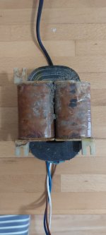
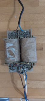
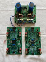
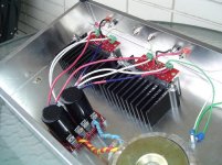
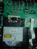
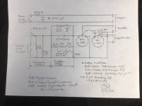
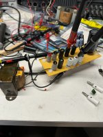
Update Sept 24, 2022: Nice build with linear PSU by member Tommost:
1664024933000.png


Edit Aug 15, 2022: 
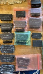
Workaround to supply chain shortage of N131 DCDC buck converter.

Edit July 24, 2020: Review of the TPA3255 amp by Redjr
TPA3255 Reference Design Class D Amp GB

TPA3255 Reference Design Class D Amp GB

Redjr has provided files to allow us to make professional looking front/rear panels that look like this:
867116d1597094895-class-amp-photo-gallery-p1020239-jpg

867119d1597094994-class-amp-photo-gallery-p1020268-jpg


Edit June 22, 2020: silk screen error on R203/C203. They are swapped. Thank you to VladC for catching this. More here.

Edit May 20, 2020: Redjr is the first to test his TPA3255 out and he says it sounds great. He used it with a Connexelectronic SMSP, which I previously found to be unsuitably noisy when tested with the 3e TPA3255 and Chinese-made blue EVM clone TPA3255 boards (ubearable hiss sound). But since Redjr says it is silent when used with the present TPA3255 amp, I had to give it a try. And it is quiet with my amp! It must have to do with the layout, the extra RFI/EMI filtering, or maybe the quality components from a Mouser supplied BOM. But my TPA3255 design is compatible with a 400w and 800w 48v SMPS from Connexelectronic. This opens up another viable PSU option for folks waiting too long for the Aliexpress 800w LED PSU.
TPA3255 Reference Design Class D Amp GB

Edit April 23, 2020: The first production verification amp was tested at the reference condition of 10W into 10ohms at 1khz and achieved 0.0011%THD vs the TI specified 0.0021%THD with PFFB enabled:
837048d1587662608-tpa3255-reference-design-class-amp-gb-tpa3255-v002-10-0vrms-10ohms-fft-pffb-victors-osc-jpg


The 1W case at 3.16Vrms at 10ohms gives 0.00074%THD:
837049d1587662608-tpa3255-reference-design-class-amp-gb-tpa3255-v002-3-16vrms-10ohms-fft-pffb-victors-osc-jpg


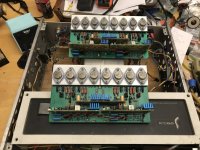
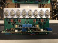
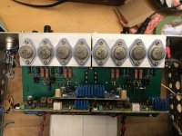
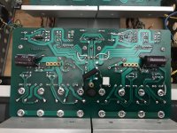
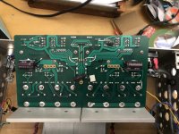
Here is the fully built amp - made in USA:
836851d1587609199-tpa3255-reference-design-class-amp-gb-67aa1113-6c7f-4ff0-91da-9f8655028f17-jpeg


Edit Jan. 10. 2020: Pre-Orders for the Ready to Run (RTR) Stereo BTL fully assembled and tested amp can be placed here:
RTR TPA3255 Reference Class D amplifier | Etsy
Pricing is $227 ea, shipping is automatically calculated based on 14oz shipping weight and 8in x 6in x 5in box. Shipping in USA will be USPS Priority Mail by default.

Edit Nov 12, 2019: Updated BOM with corrected R221 and W1xx jumper programming (1210 0R resistors) for Stereo Balanced Input and Stereo BTL Outputs:
TPA3255 Reference Design Class D Amp GB

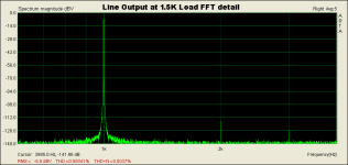
Final Test w/ correct current limit programming resistor, showing FFT at 20.3W rms into 3.3 ohms showing THD is 0.0021%:
794180d1573531774-tpa3255-reference-design-class-amp-gb-tpa3255-3e-amp-8-19vrms-3-3ohms-r121-22k-jpg


Amp was also successfully tested at 200W rms into 4ohms using a large wirewound heater dummy load:
794241d1573562561-tpa3255-diy-discussion-design-etc-a5d73f3c-af52-4a95-8847-96be8d8ad004-jpeg


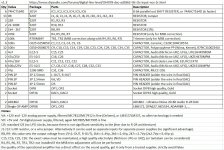
Edit Nov 5, 2019: Build notes/errata on Schematic and BOM
1. One correction to the schematic and BOM that I caught while building this was the value for R221 which sets the max current before the auto-protect kicks in. 220k is not a valid value. Use 22k for 17A (max value). Unless you want to limit it then use the table in the data sheet to set the appropriate value.

2. One other thing are the resistors R275/276 for the LED status lights. 1k is way too bright. I would go with maybe 4k7.

Edit Oct 31, 2019: THD and all-orders of harmonic distortion up to H9 vs Freq up to 10k for 5.6Vrms into 4 ohm load:
783516d1569420234-tpa3255-reference-design-class-amp-gb-tpa3255-rev0b-5-14vrms-6-6ohms-btl-sweep-jpg


Edit Oct 7, 2019: 20W into 3.3ohms FFT looks very nice. Dominant second order harmonic distortion and dominant even orders. About 0.0024% to 0.0029% THD and noise floor is very low. This is with 12v battery feeding 800w DC-DC step up to 51v:
784656d1569792221-tpa3255-reference-design-class-amp-gb-tpa3255-v0b-8-12vrms-3-3ohms-fft-jpg


This is with 120VAC wall plug powering an 800w (48vdc adjusted to 50v) SMPS (Aliexpress $44 LED PSU), also 20w into 3.3ohm load:
785019d1569942762-tpa3255-reference-design-class-amp-gb-tpa3255-v0b-8-14vrms-50v-800w-smps-fft-02-jpg


Setup with 800w SMPS:
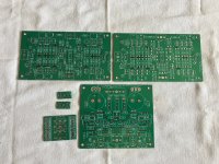
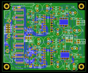
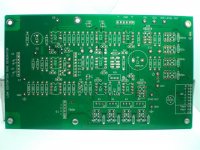
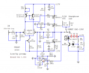
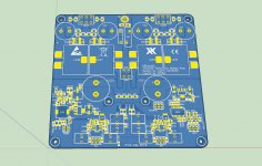
784970d1569915442-tpa3255-reference-design-class-amp-gb-tpa3255-v0b-8-12vrms-setuup-50v-800w-smps-aifeng-clc-jpg


Render of revised v01 layout with corrected silkscreen and 3.3v LDO pinouts:
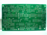
786083d1570368105-tpa3255-reference-design-class-amp-gb-580475fd-4b4d-495f-8d75-effd83c244d7-jpeg


Bottom side:
786084d1570368105-tpa3255-reference-design-class-amp-gb-9e41ec5b-b52c-49f8-b7e8-962171b84032-jpeg


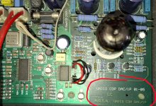
Edit Sept 27, 2019: The amp is up and running! Sounds great and measurements are very promising.
783331d1569353432-tpa3255-reference-design-class-amp-gb-tpa3255-test-success-03-jpg


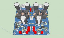
Edit Aug 17, 2019: latest 3d render with improvements (listed here) included:
775839d1566058237-tpa3255-reference-design-class-amp-gb-f6578a48-52aa-4283-aa4e-e2efbc5affbf-jpeg


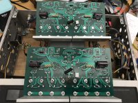
Latest bottomside of PCB (note extensive use of groundplane and large short triangular traces for power input and bulk caps all connected to Vdd pins):
775838d1566058237-tpa3255-reference-design-class-amp-gb-ede8becc-1d12-4494-85de-af340f7e4115-jpeg


***** ORIGIBNAL THREAD START *****
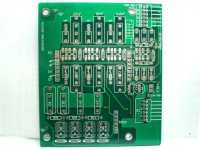
3D render of TPA3255 Reference Design with components populated (top)
771900d1564643487-tpa3255-reference-design-class-amp-gb-tpa3255-3d-top-jpg


First some history... When I first got started in DIYA projects back in 2012, there were no cheap premade Texas Instruments TPAxxxx Class D amps available. Back then, I had to make my own, and I did it with a 25w TPA3118D2 (closely related to the super popular TPA3116D2 in the Juggernaut thread inspired by my experiments in P2P SMT Class D amps).

My first DIY amp ever, a dead-bug flip-chip
The TPA3118 sounded fantastic and eventually, inexpensive variants started popping up on Aliexpress and eBay, culminating in the ubiquitous $12 TPA3116D2 50w Class D amp. I used the TPA3116 for many years in many speakers, often driven by a miniDSP for 2-way to 4-way active speakers. Somewhere along the way, I switched to Class A amps, and you know the rest of the story - culiminating in the popular Alpha series amps and finally, the ABBB.

So what brings me to go back to my Texas Instruments Class D roots? Well, there has been a lot of development by TI over the past 6-7 years and I need some more power to drive some PA speakers and subwoofers. I have a current subwoofer project that has 4 drivers, each driven by its own amp channel and DSP. So I needed a way to make circa 150w to 200w per channel at 8ohms. The TPA3255 is perhaps the best-in-class Class D amp to do this job. One thing that really piqued my interest is that the TPA3255's datasheet says that it only has 85uVrms of noise with no input signal. That is a super quiet background!

So I have been working with JPS64 and Jhofland to develop a new Class D amp based on the TI Reference design, but with some tweaks to make it even better. The design philosophy is to keep the amp more general to allow the user to select SE, BTL, or PBTL operating modes rather than force the user to the typical BTL-only offerings available on eBay/Aliexpress. The TPA3255 when operated in SE mode provides for 4 channels of output, and the audio quallity is very high as the harmonic distortion vs frequency is flat rather than rising (as is the case for BTL). It is also a good thing to keep the possibility of balanced input for the amp to enable a nice quiet drive for folks with high end DACs or preamps. We also added some nice features to make the amp easier to use and more reliable. Like Molex Minfit Jr connectors for quick and reliable connections rather than screw terminal blocks. An NTC ground lifted chassis ground Faston spade is also provided, as well as a header block to allow master/slave operation and also carrier frequency selection. Basically, all optional features are kept to allow the user the widest latitude of how they want to apply the amp.

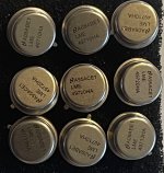
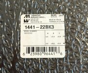
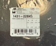
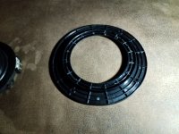
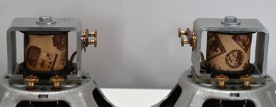
We are also mounting the main TPA3255 chip on the bottom side so that its thermal pad faces down towards the mounting surface. In this way, the board just needs to be mounted to a metal chassis with the usual standoffs and a small thermal conductor block (aluminum or copper) can be used to mount this amp inside a sealed (non-ventilated) chassis, yet still permit adequate cooling. It eliminates the need for a separate heatsink element. Of course, the amp uses only the best symmetric star-grounding-centric layout methododologies that you have come to know and love from JPS64. Don't forget the thousands of via-stitched traces for extra low impedance current paths. Finally, the crown-jewel of the design is use of premium high current CoilCraft flat copper wire shielded inductors. Those of you familiar with souped-up TPA3116's will reognize these as the ultimate inductors for Class D amps. They look cool too.

The design ended up at a generous 120mm x 124mm and will be 2.0mm thick with 2oz copper traces and ENIG finish. Typical JPS64 via stitching now covered with solder mask (tented vias) to reduce solder bridges. An on-board DC-DC converter provides the necessary 12v auxilary voltage for operation. Maximum power supply voltages is 51vdc single-rail. Typical 48vdc SMPS are perfect for powering this amp. If you already have a 400VA trafo that can make 48v to 51vdc, it can work very well too.

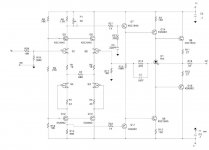
Schematic is in the PDF file below. Board is 120mm x 120mm with four M3 bolt holes offset 4mm from the corners or 112mm x 112mm CTC.

If you are interested, please add your name, number of boards, and country to ship to below.

A huge thanks to JPS64 for his amazing layout of this amp, and also thanks to jhofland for helpful advice on the schematics.

I expect the pricing to be $32 ea and the usual shipping of $5 for CONUS, $10 for CAN, and $15 for everywhere else for up to 4 boards. Additional shipping charges for larger quantities of boards. I still need to order the verification board and build and test to make sure it works before the production boards can be ordered.

GB Interest List example:

JaneDoe - 2 boards - USA

Edit June 3, 2020: If you have ordered a bare PCB, please use this BOM v002P. It contains all the corrections found during production. PM me for an updated schematic if you purchased a board or a RTR amp.

Edit Jun 21, 2020: There is a typo on line 9 of the BOM, it should be 0.01uF 100v X7R 1206. TPA3255 Reference Design Class D Amp GB

For R1021 to R1024, choose any value from 10R to 220R, 51R is a good value, 1% metal thin film, 0805. It is part of the input RFI filter and I am finding that original 2k2 was not needed and attenuated the input signal. Even 0R (jumper can work).

Edit June 22, 2020: there is a design for thermal spacer here - CAD CNC file.

Edit June 19, 2021: how to install thermal paste and under mounted heatsink.
TPA3255 Reference Design Class D Amp GB

Edit Feb 19, 2023: alternate part for SOT-223 12v LDO is MIC2920A-12WS-TR

Attachments

  • TPA3255-3d-Top-PCBonly.jpg
    TPA3255-3d-Top-PCBonly.jpg
    241 KB · Views: 12,831
  • TPA3255-3d-Top.jpg
    TPA3255-3d-Top.jpg
    216.5 KB · Views: 22,369
  • TPA3255_Class_D_SCH_001.pdf
    TPA3255_Class_D_SCH_001.pdf
    64.8 KB · Views: 2,702
  • Like
Reactions: BurntCoil

Choosing a capacitor at the input of an amplifier

Hello everyone,

At the input of an amplifier, we put a capacitor of a few microFarads to block the possible continuous component coming from the preamp.

What type of capacitor gives the best results?
  • a chemical type Silmic II, BlackGate, Nichicon Muse,
  • a MKP (Polypropylene)
  • a MKS (Polyester PET)
  • a MKT (Polyester)

What is your experience in the field?

Thank you for your feedback.

For Sale Siemens UAA180 Led Bar Driver. NOS

For sale, Siemens UAA180 IC’s, new old stock. 40 pieces available, € 7,50 a piece, € 6,50 a piece buying 10 pieces, € 5,00 a piece when buying 20 pieces (full rail). Can be shipped using regular mail. Ask for a shipping quote for your country.

This IC is used in many vintage amplifiers. See attached datasheet for further information.

IMG_7603.jpeg
IMG_7604.jpeg

Attachments

More snubber musings

First, let me commend to your reading Mark Johnson's excellent article in Linear Audio "Soft Recovery Diodes Lower Transformer Ringing by 10-20X".

I did a replication of Mark's Test fixture, some of the values are a bit different. (Was a bit puzzled that Figure 3 in the article specified a 1N5262 Zener diode, but I had one and tried it out.)

I used an old transformer, probably 1960's vintage, which I was guessing would have high leakage inductance, sure enough it measured 95uH compared to 41uH for an Antek toroid.

I was expecting the ringing of this transformer's leakage inductance and a 1N4002 diode to be in the 10's of kHz, instead almost 400kHz.

Attachments

  • IMG_2140.JPEG
    IMG_2140.JPEG
    420.4 KB · Views: 227
  • Snubber Test Fixture.png
    Snubber Test Fixture.png
    17.3 KB · Views: 236
  • SDS2204X Plus_PNG_19 1N4002 Ringing Magnitude.png
    SDS2204X Plus_PNG_19 1N4002 Ringing Magnitude.png
    64.7 KB · Views: 219
  • SDS2204X Plus_PNG_18 1N4002 Ringing.png
    SDS2204X Plus_PNG_18 1N4002 Ringing.png
    77.9 KB · Views: 190
  • SDS2204X Plus_PNG_17.png
    SDS2204X Plus_PNG_17.png
    70.7 KB · Views: 200

For Sale Panasonic Film Caps NEW

I am helping a friend close out an old repair shop, in exchange for my time he is giving me what I want for myself.

I have a large number of Panasonic film caps that he gave me. Far too many for what projects I will do.

They are almost all still in original sealed bags.


1)ECQ-E 1.5UF 250V I have five bags of 100 each $25 per bag


2)ECQE6104KF CAP FILM 0.1UF 10% 630VDC RADIAL EIGHT BAGS OF 100 $20 per bag


3)ECQE2105KF 1.0UF 250V three bags of 100 $20 per bag (these are marked 250HI and are larger item 4)


4)ECQ-E 2105KB 1.0UF 250V two bags of 100 each $20 each (these are marked L250)


5) ECQ-E2225KB 2.2UF 250V one bag marked 300 but is open, number unknown. $125


6) ECQE 2.2UF 250V caps marked 225K N250 five bags of 100. $30 per bag

minimum purchase $50, shipping to USA only, shipping is actual cost, payment is PP F&F. I can provide my eBay account as a feedback reference

Attachments

  • DSC08017.JPG
    DSC08017.JPG
    562.8 KB · Views: 98
  • DSC08019.JPG
    DSC08019.JPG
    617.5 KB · Views: 104
  • DSC08020.JPG
    DSC08020.JPG
    594.5 KB · Views: 96
  • DSC08021.JPG
    DSC08021.JPG
    408.9 KB · Views: 88
  • DSC08022.JPG
    DSC08022.JPG
    623.8 KB · Views: 102

For Sale Oleg Rulitt Solver Lab 8 field coil speaker drivers

Wonderful full range field coils very hard to come by i have never seen another pair for sale in the UK. Hand made by Oleg Rulitt in Germany. Using vintage frames and coils with his own paper cones. They need 0-120 vdc to drive them i found 72-75 vdc worked well in my open baffles using a vari-ac transformer feeding 2 simple power supplys made up from bridge rectifiers and a capacitors. There is a fair bit about these on the web and a good review on glow in the dark.com. Only selling these because i want to move up the Oleg Rulitt field coil chain. One word of caution they have exposed electrical contacts on the rear so not for use with children around. Looking for £800.00 +UK shipping. Or collection from Chichester West Sussex.
Please note no power supplies are inclued.

Attachments

  • DSC_0654_copy.jpg
    DSC_0654_copy.jpg
    247.2 KB · Views: 130
  • DSC_0655_copy.jpg
    DSC_0655_copy.jpg
    230.6 KB · Views: 132
  • DSC_0655_copy2.jpg
    DSC_0655_copy2.jpg
    219.8 KB · Views: 124
  • DSC_0658_copy2.jpg
    DSC_0658_copy2.jpg
    260.5 KB · Views: 123
  • DSC_0655_copy3.jpg
    DSC_0655_copy3.jpg
    205.4 KB · Views: 132

EAR834P is not what it seems

A friend of mine has an EAR834P phono preamp in for repair and noticed two fets in the front end, wired up as a cascode with the first 12AX7. This is not what the schematics circulating on the net show. Before anyone starts it is an original unit not modified. What gives? Schematic attached.

Attachments

12-15L portable speaker subwoofer

I'm looking to design a portable (backpack) speaker. This will be a two-way speaker with DSP, and I'm trying to figure out how to do the subwoofer part. The volume occupied by the subwoofer part would be around 12 to 15 liters. As for characteristics, I want the subwoofer to be more or less flat down to 35 Hz if possible, so deep rather than boomy. As for power, somewhere in between 70 and 150W is my ballpark.

A 4 ohm driver would be ideal as my amplifier can only push around 70-80W into 8 ohm speakers, but 8 ohm could be justifiable if a really nice driver is available. As for budget, around €80 max for the driver would be ideal (I might build 2 for stereo). I'm a newbie to subwoofer design, but from what I've gathered, drivers for compact designs benefit from low Vas, low Fs, low Qts, and high Xmax. With this in mind I combed though the SoundImports catalog and made a spreadsheet of every woofer within that budget range (see attachment). The most promising contenders I found were the Peerless by Tymphany SLS-P830946 and the Dayton Audio DCS165-4. I couldn't find a good 8 ohm contender.

As for the type of enclosure, I was thinking of either a folded transmission line speaker or passive radiators.

I could use some wisdom here. If someone could point me in the right direction or provide some resources I would appreciate that.

Attachments

Projects by fanatics, for fanatics
Get answers and advice for everyone wanting to learn the art of audio.
Join the Community
508,228
Members
7,908,893
Messages

Filter

Forum Statistics

Threads
407,208
Messages
7,908,893
Members
508,228
Latest member
Jurij951