Tri Amp Power Supplies

I built a tri amp two years ago with three separate power supplies, one for the base amp, one for both mid and high frequency amps and one for the controls, filter and attenuator. This took up a large cabinet but works fine.
I intend building another tri amp with all the amps using discrete components due to obsolete chips. The power supplies for this tri amp would be separate for each of the amplifiers and a fourth ps for the controls, filter and attenuator.
The space requirements would mean a very big cabinet.
My question is - could switch mode power supplies be used without creating interference problems. I have never used a switch mode ps and have only read of the interference problems with them in the past.

Connect 2 outputs to one speaker???

I have a simple question that's probably been asked and answered before (I tried searching but couldn't find it)

Can I connect two outputs on my carstereo to one speaker? For example in my 2-door (and 2-speaker) car, can I connect the front+ output AND the rear+ output to the speaker's + input (and same with the -) on each side/channel, to utilize my 4 channel stereo better?

And if so, what happens to the audio signal? In my mind it shouldn't affect the audio signal at all, but I could be wrong.

Aleph 40?

I have the BrianGT mini Aleph board set and would like to build an Aleph 40: 8 output devices, 6 on the output boards, and 2 on the main board. Yes, I know this will make the enclosure more challenging, but I have some ideas.

However, I have some questions. Sorry if these have been asked before.

1) The parts list I found says the bias resistors for the output board should be 0.47 ohms, but the schematic I found shows them as 1 ohm. Which is correct, and is this also correct for 8 output devices?

2) I don't have ZTX450/550, but I have BD139/140. Can I use these?

3) I have lots and lots of IRFP044. Any issues using these? Can I turn up the wick with these? How?

Need help understanding Haffler DH220 Design

Hi,

I'm looking for help in understanding the circuit design for the Haffler DH220.

First, a bit about me. I have a degree in physics and did some electronic labs in college, but I'm not an engineer and that was 20+ years ago. I do some electronics hobbying, mostly fixing broken stuff, but don't have any experience in audio projects, though that seems to be a hobby waiting to happen. I've good analytic and mechanical skills. I work as an IT Architect and restore motorcycles as a hobby. All this is to say that I think I'm up to the task of understanding this, but I could use a little help.

I have a working amp that I want to refurbish as it sounds a bit "dead". Not dead like it doesn't work, but just not very open, vibrant, etc. My thought is that I'll upgrade capacitors and replace components as needed based on testing them.

However, rather than just jump in, I'd like to have a solid understanding of the circuit first. From studying the schematic (posted below with my markup), reading literally hundreds of posts on this and other forums, reading appropriate sections electronics texts (The Art of Electronics, and Sloan's books High Power Audio Amplifier and Audiophile's Project Sourcebook), and reading through Marshall Leach's description of his amp design (very helpful), I have a pretty good high level understanding of the Haffler design. However, there are some sections of the circuit I don't understand.

What follows is my understanding (please correct any errors) as well as my questions.

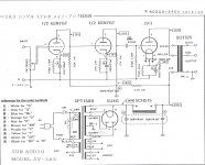
The design follows Lin's 3 stage architecture. It is a complementary design, so in the following (and in my markup of the schematic), I'm just going to focus on 1/2 of the circuit

The input impedance is set by R1. The input is ac coupled through C1 and C2.
C21 and C22 are to remove any power supply ripple.

The input stage is a differential amplifier formed by Q3 & Q4 with a current source in the tail formed by Q2, D4, D5, D6 and R9.

The input stage is biased by the voltage divider that is adjusted by P1.

Output from the input stage is from the collector of Q3 and feeds the 2nd stage (the VAS). The 2nd stage is a Darlington Pair (Q7 & Q8). Diode D9 seems to work like a Baker Clamp to protect Q7 from saturating. If I understood my reading correctly, a Baker Clamp would have another diode, so I'm not sure if this actually is a Baker Clamp or not.

The output of stage two is from the collector of Q8 and feeds the base on the output driver Q12. Q12 is biased by the amplified diode formed with Q9, P2, and the associated resistors. Q12 is configured as an emitter-follower and the emitter output feeds the parallel MOSFETS that complete the output stage.

The output is run through some filters composed of L1& R36 along with R35 & C19 and R37 & C20 (I believe these two RC segments are part of a Zobel network).

Questions:

How is this 2nd stage biased? Is it through R9 and C4? If not, what is the purpose of R9 and C4?

What is the purpose of R34 and C18? My guess is that R34 is part of the feedback network and C18 provides a mean to bypass R18 for certain frequencies to adjust feedback.

The circuit near point A in the schematic is the feedback network, correct? If someone feels like explaining how that functions, that would be great, though just knowing it is the feedback network is enough for my general understanding.

What is the purpose of C23?

What is the purpose of C11, C12, and C13? More power supply filtering?

One of the output stage input drivers (lower part of diagram) has some capacitors in it's circuit segment (C10 and C17) that the other driver doesn't. What is the purpose of those and why on only one driver?

What are the diodes in the middle of the diagram for (D11, D12, D13, & D14)?

Finally, can someone explain the purpose of the Resistors and Capacitor (R401, R402, and C401) in the output stage? Are those there for biasing? I'm having a hard time wrapping my head around that detail.

Thanks in advance for your input on this. If I get a thorough (and accurate) understanding of the circuit, I'll write it up and repost it.

James
dh220_schem_markup.jpg

Luxman LV-105u replacing outputs help!

I need some info regarding replacing the output transistors. I realize finding original replacements is not going to happen. I have purchased a pair of IRFP9240 and IRFP240 after reading some threads about this amp.

I need to know if I need to modify anything else inside to get these to work. Also should I replace both channels with the new parts. I believe that one channels original outputs are still working. So do I need to replace both sides?

I did try and install these new parts on the dead channel. Everthing went OK I thought. But as I turned it on and try to adjust the Bias I am getting 0.0v on one side and the other seems fine I can set it to the 65 mv the service manual asks for.

I have done many tests to see where I am getting voltage. Or for short resistors. I found a couple that were out of tolerance and replaed them accordingly. Voltage is making it to the main board. On the side with the original outputs. My measurements are not to far off the required values. The other side gets voltage but nothing across the emitter resistors. I cannot find the short. Please help

I am not looking to send this out to be fixed by a tech. I want to do it myself. I do have some knowlege in electronics but I am not a tech or professional. Please anyone that can help me I greatly appreciate it.

Do I need to look at the driver board? Or main board? or other mods to get these outputs to work.

The amp's tubes both light up. I really like this amp. Please reply.

2x5V and 2x3.3v lt3042 doubles power supplies

i have for sale four lt3042 double power supplies (picture has 5 but i sold one already), ideal for dacs, clocks etc. they are good, just need transformer and are ready do power!
2x5V and 2x3.3v lt3042 doubles power supplies.

asking 45 euros for all, including shipping in Europe.

😱😱

Attachments

  • 20200322_221914.jpg
    20200322_221914.jpg
    395.3 KB · Views: 268
  • 20200322_221924.jpg
    20200322_221924.jpg
    390.1 KB · Views: 255

Looking for a power on LED that does more.

Sort of throwing a Hail Mary if anyone has come across a circuit to jazz up the front panel of a piece of equipment? Sort of like a front panel LED that doesn't just stay solid, but pulses to output power, or pulses to music, etc? Thinking that must have been used some time some where on a commercial piece of gear, maybe even just an elegant application of a special purpose IC.

I know you can rig up a simple transistor circuit to act as a single LED to pulse with signal, but doesn't seem like a good solution, as setting would only work at one volume unless there was AGC as well.

Circa 1980 Sharp stereo amplifier. Pop! now just hiss.

Hi All,

Just a quick question about my Sharp stereo amplifier model SM-1122.

I was in the garage listening to the radio using the Sharp model ST-1122 AM/FM stereo tuner when I heard a loud POP. Immediately there was quite a bit of hiss/static along with the music, similar to when you get this analog tuner close to a station but not really on it yet. I walked over and looked at the tuner signal meters and they were close on but I adjusted the dial anyway. No help.

It's an old set up and I have used DeOx on the switches and buttons once about 3 years ago. So every once and a while I have to cycle thru the buttons on the tuner (AM/FM, mono, air check) to fix little issues. I cycled thru the buttons on the tuner, no help. Then I cycled thru the buttons (loudness, mono)(phono, tuner, tape, aux) on the amp. No help.

That's when I noticed that no matter what source button I selected I now had a constant loud hiss that is not affected by the volume control.

Has the amp finally given up the ghost?

R/
Jim

Any idea's, Dynaudio issue

Any idea's, Dynaudio issue

In 1991 I built a pair of Dynaudio Twynn speaker with Dynaudio 17 W-75 woofers. Over time, (in the past three years) the top drivers (mid-range speaker) on both pairs has started to rattle with music that has heavy base or if I play them a little loud. I am guessing that the voice coil is bad. Any feedback on if you think that is my problem?

My real question is;
Can I get them fixed? If so at about what cost? and by who?

Or;

What is a good replacement driver for the Dynaudio 17 W-75's that would work with my Dynaudio Twynn setup and be as good or better than the Dynaudio 17 W-75's .

Thanks for the help,
John..

WTB: WIN7 Laptop USB2, w/Charger etc or Trade for Tubes

Hi Y'all,

Maybe someone out there has a something like a Dell Laptop with
win7 on it that they aren't using any longer. I need one so that I can use
my QA400 analyzer through it on a USB2 port.
charger that works etc.

Probably needs the 8MB RAM and whatever video memory will
work. The larger the screen the better.

QA400 doesn't work on WIN10 machines.
It worked with WIN8 but that is problematic.
with WIN7 it worked just fine.

PM me with what you have or post a pic here etc and price.

PS - I'm on a very limited budget.

Open to trade for tubes or for sale.
Matched NOS Pairs:
7581A NOS,NIB Philips ECG7581A for reference only ebay $429.99 LINK
Mine are triple matched, factory, distributor, then in actual amp. I'd let these
pairs go for $325 plus actual shipping. While they last.
Gm = 4700, Ip = 50
Amp match varies a bit as it's not as controlled
as a precision matcher. These voltages were measured
through a 10 ohm Dale RN65 to ground and subsequent
extrapolation to current draw at 450V if I recall.

Tube were burned in for approx 30 minutes to stabilize,
then also checked for noise, and microphonics by chopstick
testing. I guarantee these tubes!

5 - .439 = 43.9mA
6 - .420 = 42.0mA


7 - .426 = 42.6mA
8 - .404 = 40.4mA
9 - .419 = 41.9mA
10- .423 = 42.3mA

The only non-performance issue that I noticed with
these tubes is they've been in in-home storage cabinet
and each tube has been protected with a green puffy
styrofoam peanut. They exhibit a slight fog on glass
appearance that I wiped off the two tubes in the pic.
Along with the very gentle wiping, some of the green
logo edges started to lift also.

6V6 GT NOS Mazda "Guerre"
This pair only, $125 plus actual shipping

Gm = 26.0, Ip = 3.10
Gm = 26.0, Ip = 2.90

Cheers,

PAM8403 Parallel

I've been playing with the PAM8403 amp. I built a small mono speaker as a children's project and thought it would be sensible to parallel the two output channels for more current capability (yes the advantage of this depends on load impedance and voltage rail).

At first I put some 0.22R resistors in line with each output and tied them together. This is standard for a class-AB amp with the resistors helping to balance the current from each output. When I increased the volume the amp cut out to protect itself.

A bit of reading revealed that the spread-spectrum output uses an independent randomised modulator for each channel. That means the switching carrier for each output channel is not matched, even when you link the inputs to the same source. When the outputs signals are not perfectly matched the outputs try to drive each other which ain't good.

The solution is simple - add LC filtering on the outputs before tying the channels together. The inductor (33uH) / capacitor (220nF) filters out the switching carrier allowing the outputs to work together. Just thought I would share this as I found a few others on the interwebs trying to do the same. Hope this helps.

An externally hosted image should be here but it was not working when we last tested it.

Why care about 60 degree off-axis response?

I would like to put this up to discussion, because there may just be something that I don't understand.

I believe I have a sweet spot for 8" full-range or mid-range drivers in a 3-way setup. Being fairly new to this, I came across the "beaming" issue that is often expressed, which is more of a problem the larger the driver gets.

One article I came across on this topic is from Troels Gravesen, which I believe is a well respected speaker designer:
beaming

Now here is what I don't quite get: He talks about how a 60° off-axis response influences the FR of an 8" driver. The problem is obvious, yes. But, why care? Even if I would not toe-in my speakers at all, how likely is it that I listen to my music at 60° off-axis? And even if I did, most music material is more or less equal in both channels, so if I am off-axis 60° from one speaker, I am probably at nearly 0° to the other.

I am not here to say that beaming is not an issue. But to look at 60° off-axis responses to me appears to make no sense.

Or am I missing the point somehow?

DIY Binaural Mics

Hi all,

I've liked binaural recordings for a while. Not the weird YouTube videos, but ones where you've got musicians playing around you and it sounds like you're right there (links at the bottom).
Well, one of the bands I work with would be perfect for that sort of thing, and they're up for it.

Shopping list:
2x Behringer ECM8000
1x polystyrene head
2x latex ears (the ones I picked up were for acupuncture practice).

I had one of the mics lying around, and picked up a 2nd for cheap on the usual auction site.

Sliced the head in half horizontally, cut channels for the mics etc, gaffer taped it all together and had a listen.

The result was, without doubt, an auditory disaster. No bass, horrendous peak in the mid-high range.

As usual, I did some measurements. First up, with my reference headphones, Shure SRH840s. To me, they sound very clean and neutral. Cans by Sennheiser, Sony, Audio-Technica of similar price point all sounded wrong to me.
Anyway, I'm not here to go on about headphones.

Here's a graph.

An externally hosted image should be here but it was not working when we last tested it.


So that's put the headphones on the head, sweep through the headphones and run the head-mic into REW.

I tried EQing that response flat, which sounded half-decent, but not great. Then I did some reading around with terms like "Diffuse Field" among others.

Next up, I put the good measurement mic (Beyerdynamic MM1) up in front of a Bose MusicMonitor, generated a calibration file, and then connected up the head.

Of course, the frequency response is angle-dependent, so here's a few graphs.

An externally hosted image should be here but it was not working when we last tested it.


An externally hosted image should be here but it was not working when we last tested it.


An externally hosted image should be here but it was not working when we last tested it.


I took an average of those three, which looks like this:
An externally hosted image should be here but it was not working when we last tested it.


Then I EQ'd that to be pretty much flat, and had a listen.

Much much better. Not perfect, but certainly closer than I got by measuring with headphones.

My phone doesn't want to talk to my laptop at the moment, but when I get that sorted I'll upload a couple of photos of Ed. He looks like a polystyrene head that's been stabbed with a couple of measurement mics, and that's pretty much what's happened.
One day he might get a wig.

That's all for now. I might try playing guitar while walking around and upload a recording.
I also thought it might be a good way of evaluating speakers, but I don't think its quite "there" yet, so that'll be a while off.

Chris

PS - recordings links:
https://www.youtube.com/watch?v=ecOrBqQAuXg
https://youtu.be/itLxXeyM2aM?t=58s

Solid electrolitics vs audio grade electrolitc capacitors

Hello everyone. Just curious if anyone has tried the new solid electrolitic caps for audio applications-ie preamps,cd players or amps & how they compare to the audio grade lytics such as elna and nichicon muse. These are the new caps that most of the manufacturers are putting in motherboards on computers now because to their much longer lifespan and better frequency characteristics. I looked some up on digokey or mouser one & they were expensive & didn't have very high voltage..

Toroidal Transformer replacement

Hi all,

I would like to replace a toroidal transformer with Pri 230v / Sec 17.5v - 0 - 17.5v and 8.5 V - 8.5V (5wires). I haven't found anything similar with the 0v center tap.
So i was thinking about to use this one:
30W / 30VA R-Core Transformer PRI 115V/230V 50/60Hz SEC 9V+ 9V / 18V + 18V | eBay

My theory is i need to connect always wire 1 from each color together to have the 0v and the second wire for each voltage as the positive.
But because both sides of the coil have the same color, i will never know which one i use as 0v and which one as positive... do you think this will matter?

Thanks,
Thomas

Help with Gemini Preamp EQ

Hi All,

I made three way speakers, then tri-amp system.
As preamplifier I'm using Gemini PA-7000. Changed transformer, capacitors, BA4558 replaced by NE5532. Found 20% difference in channels output. Temporary 8 pin B20K potentiometer (broken in central loudness dent) replaced by B33K. Still 5-10% difference. Checked first NE on main board and difference was 2-4%(Vcc-14.7/Vcc+15.2). On the second NE5532 placed on Equalizer Board found x1, x10 difference in +/- inputs on left and right channel. Output difference was 15%. With small movement of treble or mid potentiometer the situation become better. Unfortunately there is no direct switch to bypass EQ.
Could You please help me with advise How to bypass EQ.
Thanks in advance
Rauf

Attachments

  • Gemini 7000.png
    Gemini 7000.png
    318 KB · Views: 158

Testboard LME49830

Hi there,

I have built a test board for the LME49830, exactly according to the datasheet. Only conventional components were used, no SMD.
The board works. The sound is warm and clear.
If anyone can use it, I can upload the layout. I do not want it to develop. It was just for fun, the LME49830 has a friend gave me.

regards Olaf

Attachments

  • LME49830_Proto_Top.jpg
    LME49830_Proto_Top.jpg
    193 KB · Views: 1,515
  • LME49830_01.jpg
    LME49830_01.jpg
    256.3 KB · Views: 1,444
  • PCB_TopView.JPG
    PCB_TopView.JPG
    127.2 KB · Views: 1,455
  • schematic.JPG
    schematic.JPG
    110.8 KB · Views: 1,464

Capacitors

Hello,
I have a power supply tranny and two dual mono PS boards from Electrocompaniete AW50.
I would like to use it on another project. The capacitors are 4pin Roe Elna 10000mf 40V.
Any way I can test them to see if they are still good?
Or should I replace them with other capacitors since they are at least 30 yo? would be very helpful if someone recommend how to hook up normal 2 pin ones in this layout, if it is even possible.

any recommendation would be appreciated.

Attachments

  • IMG_9260.jpg
    IMG_9260.jpg
    399.6 KB · Views: 148
  • IMG_9261.jpg
    IMG_9261.jpg
    650.5 KB · Views: 136
  • IMG_9262.jpg
    IMG_9262.jpg
    688.2 KB · Views: 135

buying parts for tube circuit experiments

Greetings!

So I decided to study tube amps and along with reading I would like to perform some experiments. Could more experienced eye look on my parts list and give some insights on what is missing?
The purpose of this is to learn and gather experience along the way. Any advice and suggestions will be greatly appreciated!

Tubes
6N2P, 6J32P, 6N14P, 6N3C

Capacitors
Polypropylene: 470pF, (1, 2.2, 4.7, 10, 22, 47)nF, (0.1,0.22,0.68)uF 630V
Electrolytics: (10, 22, 33, 47, 100, 220)uF - 450V, (47, 100, 220, 470)uF - 100V


Resistors
Metal film 1W 5%: 100, 470, 1K, 4.7k, 10k, 47k, 100k, 220k, 470k, 1M

Other
1n4148, hlmp-6000 LED

Pioneer PRS-D2000SPL

Hi everyone, I have recently purchased 2 Pioneer PRS-D2000SPL amplifiers, and I'm having issues with both of them. I need to replace the driver IC on them both, but the TND505MD ICs are discontinued and I've found an old thread here saying that the guy replaced a TND505MD with an IR2110S, however a modification was done, and he worded it as connecting " the Ground and Common together on the IR2110" but I can only see a COM pin on the IR2110S, while the TND505MD has a GND pin, so I assume they are similar. However the IR2110S also has an additional pin that is in use, pin 15, and it's labeled Vss, while pin 15 on the TND505MD is simply not connected. Could someone with a little bit more knowledge be able to help me after comparing the TND505MD and the IR2110S datasheets and suggest how to modify it to work like a TND505MD. Thank you for reading.

Pass Labs Aleph P troubleshooting

I recently bought my Pass Aleph P 1.7 back from a friend that I sold it to in 2014 after my position was eliminated. This is a commercial Aleph P, not DIY, with remote and uses the IRF610/9610 FETs. My friend had told me that he was hearing some random noise from the right channel, almost sounding like a dirty pot. This was when listening and not operating the volume control or anything.

When I got it back in January, it has performed flawlessly during this time; no noises, etc. that I detected. Until this weekend, when it appeared that the right channel went out. I took it down on the bench. Examining the internals, nothing appears out of the ordinary. I checked the power supplies and everything seems fine. I do have the service manual pdf.

I then injected a 1khz sine wave into the ch 1 inputs. At the output, the right channel was there, but was 1/3 to 1/2 the amplitude of the left channel. After thinking about it a bit and realizing the attenuator was on the output, I took a look at the amp section outputs for L+ and R+ at the 100R resistors R72 (R) and R42 (L). They looked good and were identical in amplitude. I then took two DMMs and connected the + of each to R42/R72 and the - to the bottom of one of the attenuator resistors in each channel. When operating the volume control, the left channel operated as expected. The right channel however was jumping around in a non-linear fashion at certain points, leading me to believe that one or more of the attenuator relays had gone bad. At this point I think I will replace all 16 of the relays (both channels).

The original relays are Aromat DS2YE-S-DC24V, which appear to be discontinued. I haven't found a datasheet for these, but Panasonic seems to own Aromat now. Any suggested replacements?

If anyone can think of any troubleshooting steps that I may have missed, please let me know. One other thing I may replace are the gain pots, but I haven't identified what they are yet, other than I know they are 2K pots. They seem to be working fine.

Thanks for any thoughts.

Making tube Rp disappear now

I recently came up with an interesting approach to make a tube (triode or pentode) lose it's Rp. (ie, go to very high output impedance) This might seem pointless, but if you want to control an amplifier's output impedance via feedbacks, it can be usefull to remove the effect of the usual varying tube Rp. This could be especially useful for SET type amplifiers where only one tube is operating (and varying it's Rp). Class A P-P amps have some (but not perfect) built in compensation for this, since one tube picks up as the other tube lets go. Class B P-P amps have far less compensation of output Z (before global feedback applied) due to non overlap of tube conduction, and that is responsible for some of the 3rd harmonic distortion they produce.

How this works is to operate g1 in positive territory (exclusively, so only some zero bias triode tubes will be suitable, most pentodes can be configured though, via low screen V, and some conventional triodes might be configurable via low plate V if they can supply enough current), and drive it with a controlled current source drive. (instead of the usual voltage source drive) The positive grid 1 intercepts a near constant small fraction of the cathode current stream (at least until the plate V dips down low enough to approach the region of g1 voltage). Lets call 1/Beta the numerical factor for fraction of plate current captured by the grid1. (so Beta is the current gain for the tube in this mode) The current source drive will automatically adjust the g1 voltage to obtain its requested grid current (and so results in the plate current at Beta times that).

So, looking at a triode, any variation of voltage on the triode's plate will automatically be met with 1/Mu opposite voltage variation on the positive grid 1 in order to satisfy the grid current requested. A pentode will operate similarly in positive g1 current drive, just with less voltage variation on the grid, due to the effective high Mu of a pentode. When the plate voltage does not effect the tube's current, we have high impedance, the intended result.

The driver circuit could be a linearized (high gm, cathode degenerated) pentode stage, maybe differential. Or a triode stage with low Rp and some series resistance to the output tube grid.

With the output stage's Rp gone, external combined V/I global feedbacks can be used to set an output impedance. (or for a low feedback design, only a weak local V feedback would be required, since the stage is already providing controlled current. This would set up a current per output voltage mode instead.)

This all would be useful if one wanted to drive a speaker with "critical damping" impedance, say.

g2 current drive might also work, but I'm not sure how well it will hold a constant Beta, since plate V will be dipping down to that V range easily. Beta would be expected to droop some when amplitude is high.

One could even get tricky, and make the output impedance vary in a specified way with amplitude or frequency to control some speaker in a way to compensate for its characteristics. This could be accomplished by a finite output resistance in the driver stage, maybe frequency affected, or frequency controlled outer impedance control feedbacks.

Just as a note. Using V and I global feedbacks have been used historically to control amplifier output impedance. But they typically require high loop gain in the amplifier to make them effective. This current (pun) approach allows one to accomplish similar effects for low or no feedback designs. More likely appealing to the SET crowd or low feedback group.

Cheap Chinese active X-O

An externally hosted image should be here but it was not working when we last tested it.


"HIFI Electronical 2 Way Crossover PCBA ClassA Power Linkwitz-Riley filter 4-Channel Output Crossover-point 2.2K Hz Free Shipping"

I've bought two of these with X-O points at 80 and 100hz for use with sub-woofers for my single driver MTLT systems.

Having frequencies down to a measured 30hz adds a subtle but valuable fullness to some music.

I used MathAudio's free plug in for FooBar to flatten out the peaks in my systems.

Anyway... Has anybody done testing on these $30 active X-Os?
Does the design look OK? 'Seems so inexpensive... less than passive X-Oers.

Thanks, Mack

A few Items for sale - Pcb's, transistors, capacitors

As I have suddenly a LOT of free time, as everyone else! Im having a clear out. All plus shipping

All not used
Clarity Cap ESA - 10uf 250v £5
Clarity Cap ESA - 6.8uf 250v £4
Clarity Cap ESA - 2.2uf 250v £2.50

F&t 10000uf 63v x2 used to test an amplifier, probably around 10 hours use, both £5

Transistor pulls from working equipment all £3 each

Motorola 2955 x2
Motorola 3055 x2
RCA 16112 x1
RCA 38494 x2
2SA1216 x2
2SC2922 x2

Pcb's not used

Peter Daniels universal PowerSupply Pcb x2 £5 each, details here - https://www.diyaudio.com/forums/audio-sector/149672-universal-power-supply-pcb.html

PFM flea, cd clock pcb £3, details here - Ray's Audio Page

Rectifier Bridge pcb from Peranders audio shop £5 details here - RFB03 Rectifier Bridge

Amp topology question/identification

Hi there. I picked up this amp recently for next to nothing. It's a high power (approx 200W into 8) , single ended input amp. It's sounds OK, but lacking some fidelity in my opinion. I'm wondering what kind of amp uses all the same output devices? In this case MJ15024.
I'm also thinking it might be worth ditching the amplifiers and utilising the chassis and 500VA 2 x 45VAC power supply for another project. If so, any suggestions ? Cheers

Attachments

  • IMG_4931.jpg
    IMG_4931.jpg
    638.6 KB · Views: 182
  • IMG_4930.jpg
    IMG_4930.jpg
    636.7 KB · Views: 190
  • IMG_4932.jpg
    IMG_4932.jpg
    721.3 KB · Views: 172
  • IMG_4933.jpg
    IMG_4933.jpg
    629.3 KB · Views: 174

S/PDIF to I2S wiht CS8416 problem unsync SDOUT at startup

Hi,
I have this system:
bluetooth module TS8970 (SPDIF) -> (SPDIF) CS8416 (I2S) -> (I2S) ADAU1701 (ANA)

The CS8416 is in Hardware mode.

When the audio startup or change trace or skip up/down the trace, seem that CS8416 sdout data is tempranealy unsync about the Master Clock and this cause an “CLIC CLIC” on output about ADAU1701.

I have tried this configuration:
each test was done in both conditions:
[CS8416 (master) and ADAU1701 (slave)]
[CS8416 (slave) and ADAU1701 (master)]

TRY1
Master Clock is Recovered Master Clock
RMCK Pin 24 CS8416 to MCLKi ADAU1701

TRY2
Master Clock is oscillator
Oscillator to Pin 25 CS8416, OMCK
RMCK Pin 24 CS8416 to MCLKi ADAU1701

TRY3
Master Clock is oscillator
Oscillator to Pin 25 CS8416, OMCK and to MCLKi ADAU1701
(RMCK Pin 24 CS8416 not used)

It seems that every time the audio stream is interrupted the PLL must hang up again. I also tried to change “Normal /Higher Phase Detector update rate” but I did not solve the problem.
Any ideas to help me?

High Power Heatsinks (UK)

I've just built an Aleph J Class A amplifier with two heatsinks salvaged from some LED light fittings.

The photo is of my almost finished project.

On offer are two more of these light fittings that gave me these heatsinks.

They are huge and enormously heavy so collection only from B98 UK.

I'll take £20.00 each for them.

Attachments

  • 20200316_135510.jpg
    20200316_135510.jpg
    807.9 KB · Views: 238

FS: Alpha Nirvana, SLB PSU, SRR DC Protection boards

For sale are a set of PCBs for the Alpha Nirvana Class A amp, Smooth Like Butter (SLB) PSU, and a set of SRR DC Protection boards. One of the SSR boards has faston connectors soldered on, it was shipped to me this way as it was the board used for checkout from that production run.


$140 shipped in US.

Attachments

  • IMG_20200419_183815.jpg
    IMG_20200419_183815.jpg
    976.9 KB · Views: 171

Xonar Essence STX ii recording - no info above 22KHz

Asus' web specs say this card will record at multiple sample rates including 96KHz and 192KHz. When used with Adobe Audition under Win10 or Audacity under Xubuntu 16.04, the files are at a higher sample rate, but there is ZERO information above a sharp 22KHz cutoff. It's as if the card itself is operating the analog-digital conversion at a lower rate and/or stripping info. See screenshot or spectral analysis.

Can anyone say they've seen the same (or something different?)

I did not see this behavior with my older M-audio Delta 24/96.

Attachments

  • SharpCutoff.jpg
    SharpCutoff.jpg
    294.4 KB · Views: 132

125asx2 in btl ?

Hi everybody,


i bought a icepower 125asx2 from a friend .

i plan to use it in btl with asymetrical ( mono cinch) input.
i ordered a cable set from ghent, china.
but now , i am not shure how to connect the right input to get the correct btl

output !
can anybody help me, my wife fears the house is burning down, in case of wrong connection !😱


thank you for your help !
jochen ( germany )

Capacitor value suggestions please

I am working on an AMC CVT-2030 which was a low budget hybrid EL34 PP amp that I got for basically nothing. Yes, the one with the output tubes soldered in. I have put in tube sockets and used a holesaw on the heat sinks to make room. I can't find a schematic for this model but there is one for the CVT3030 which is basically the same thing with a preamp. My question is about the value of the coupling cap from the drain of the driver MOSFET to the grid of the EL34. The value in the 2030 is .1\250v film. The 3030 is a 1u\250v electrolytic. I have very limited theory and design skills, is there a formula to calculate optimum values for grid coupling caps?

Jeff Bagby's Continuum Build

I think I must have gotten the (or close to) the last kit Meniscus had because the RS28A-4 tweeter is NLA, seemingly for awhile, as I notice it's been taken off of PE's site as well.

Really strange because, I am not a bookshelf or small monitor type. I bought this kit on impulse, and a bit of novelty due to having heard one pair of LS3/5a's in the later part of the 70's. I had a shop foreman, who was from England, who had carted that pair of speakers with him quite a ways around the world by that point. We (myself, and a few of the other shop guys) all hung out together after work and on weekends. Our stereo speakers were typically louder, party type speakers, so we used to joke with him about his little monitors. I had to admit though, in the small efficiency he lived in at the time, they actually sounded quite good, especially after a few beers. Anyhow, that was the only time I have seen/heard a pair of those and had totally forgotten about them.

I have already built a pair of Jeff Bagby's Fusion-12 design from diysoundgroup, which I am quite fond of, so I have a bit of confidence with his designs. So I start reading about the design goals with the Continuum and I come across a picture of the LS3/5 speakers! That tickled me just enough to instantly click the "add to cart" option! And I need another pair of speakers like a hole in the head.

Still, they're little speakers and I didn't expect much, figuring I'll use them for desktops or something trivial. I made the cabinets out of MDF so not committing to any real money in the finish in the event that they just sound so-so. Well, when I fired these little chunks up, I was so pleasantly surprised by how nice they sounded, that they instantly became pricelessly valuable. An instant, favorite small possession.

Is this the best sounding small speaker I have ever heard? Hard to say. All I can say is that even if it isn't, I don't care. I don't, or will never need a speaker that sounds better than this one in this category for a small, 2.1, music only setup. I have it accompanied by a Dayton 12" Ultimax subwoofer.

sczXHwt.jpg

Naim Nait 5i Bypass issue

Hi everyone,

I'm currently facing an issue with my (beloved) Naim Nait 5i from 2005.
When in Bypass mode I have noises coming up on the speakers.

My setup:
  • Naim Nait 5i amp
  • Audio-GD 3.32 Dac
  • HT Preamp Emotiva UMC-200
  • Computer is connected using optical fibre to the Emotiva, and coaxial to the DAC
  • Synology NAS connected to DAC with USB
When using the Naim 5i as in integrated with the NAS or PC, no issues.
When in A/V mode through the HT pream (optical f and unity gain) I'm picking all noises from the PC, hard disks, mouse movements..

So far I've tried different things:
  • Changed the PC power supply to a gold X-650 Seasonic
  • Plug the Naim 5m away from the PC
  • Add some ferrite cores on the PC and amplifier power supply lines
What worries me is that those noises are there even with A/V inputs unplugged from the amplifier so it all comes through power lines. Unity gain is amplifying all defects from the power lines..

While looking for a solution I realized that I had quite some "Humming" in A/V mode with no inputs plugged. (Ground loop ..?)

And while checking I also noticed a strong odour around the power supply capacitors in the amp. Could they be dead? No bulging on these BHC 10000uF and 4700uF

MANY thanks for any help or insight.. !!

WTB Or Trade

Hi,

Looking for the 6DJ8s that HP used in their equipment.
These are the ECC88 or E88CC, I forget which.

I've got this annoying ARC SP10 pre amp that is very
difficult to find quiet tubes in the phone section and parts
of the preamp section. Hence the need for the extremely quiet types.

If you have some and know they are quiet, please let me know
as I need them. I can trade for the Mazda 6V6 tube or Philips 7581As

Cheers,

Threshold SL10 is this cap backwards?

Hello,
Recently acquired this gorgeous Threshold SL10 but it sounds flat and clinical in comparison to my Pass korg B1. Like very flat.

So I had a peak and someone has been here before me. No surprise on an amp this old. Caps need to get replaced so they were. High quality black gate and Panasonic caps used by the looks of it.
But I noticed one cap in an unusual orientation and dining a simple image comparison shows maybe just maybe one of these 47uf 50V caps is backwards.
Am I loosing my mind?

Context:
Both are driving Hypex ncore Nc400s with Klipsch Forte 3 at the helm.
Turntable is micro seiki DD40 with nagaoka MP-150.

I really thought the Threshold SL10 was going to hand it to the Pass Korg B1 but maybe I’m just super wrong.

Would love your thoughts.
Thanks and stay safe.
Jules

Attachments

  • FA472EC3-BB54-4FAE-B200-949964B40CB0.jpeg
    FA472EC3-BB54-4FAE-B200-949964B40CB0.jpeg
    357.5 KB · Views: 94
  • 8C69418A-B695-400D-BE3F-66B0A716A634.jpeg
    8C69418A-B695-400D-BE3F-66B0A716A634.jpeg
    329 KB · Views: 96
  • 6F6CDB6E-A6B2-4770-8779-1485D6374AB4.jpeg
    6F6CDB6E-A6B2-4770-8779-1485D6374AB4.jpeg
    354 KB · Views: 93
  • F6017449-D340-4603-B4EB-6268553994E6.jpeg
    F6017449-D340-4603-B4EB-6268553994E6.jpeg
    349.9 KB · Views: 87

FS a few of the most fun builds I have done

An externally hosted image should be here but it was not working when we last tested it.

An externally hosted image should be here but it was not working when we last tested it.

An externally hosted image should be here but it was not working when we last tested it.

An externally hosted image should be here but it was not working when we last tested it.

An externally hosted image should be here but it was not working when we last tested it.

An externally hosted image should be here but it was not working when we last tested it.

An externally hosted image should be here but it was not working when we last tested it.

An externally hosted image should be here but it was not working when we last tested it.

An externally hosted image should be here but it was not working when we last tested it.

An externally hosted image should be here but it was not working when we last tested it.


These were some of the most fun builds I have done. The AO35 hammond and the B&H speaker boxes are like a blank canvas every build. The amps can be tweaked a zillion ways and you can see how creative you can be with the cabinets. If you look at the brown one you can see the patch cord reel. How awesome is that. It was of course some dry rotted speaker cable that had to be rewound with Mogami gold. I also had to put metal bottoms on the amps for shielding. These are almost dead silent but easily over driven. The brown one is also sporting a modified Newcomb TR-16. My son has been playing and collecting for 30 years and I have done tons of work on his many amps. He auditions each of these for me and every single time he is just amazed at the performance out of these compact units. No two of these ever sound the same...component, layout, tube brand and array give each amp subtle but noticeable nuances. Like I said...these are like a blank canvas and I thoroughly enjoy these builds. I know what they cost to build and 95% of the tubes are vintage but I really don't know what to ask for them. These are one off's and you will not see any others like these. Hydro dipping was expensive and they generally take about 4 - 6 hours total build time. My sons friends have all tried them out and a retired marine friend of mine played a couple local gigs a few months ago with the stars and stripes unit. I have since been inundated with requests for custom logos and configurations for different applications. Any help on pricing these units would be greatly appreciated. BTW...this site has been an immeasurable support group for tips and tricks. Thanks to all the craftsmen...one of which I am not.

500/1 LP filter does not work

My tale of woe:


About 15 years ago I purchased this 500/1 new. Installed it, worked great. That car got totaled and the amp removed about 8 years ago, and the amp has been in a drawer ever since.

I recently decided to install this amp and the 12w6v3-D4 in another vehicle. Hooked it up, no lights of any kind. Found a recommendation to toggle the signal sense switch 5-10 times. Did that, and yay it powers up. No sound though. I turned the LP filter from 12db to Off, and now it plays, but it sounds funny. Not just full range funny, not really distorted, just...not right.

I take the amp to my local car audio place, they have a repair section. The guy acts like I'm a total idiot, has this smirk on his face. Whatever. I explain that the LP filter won't work, and thus the related dials. (Bass Boost, Q, etc) don't work.

He plugs it in to his bench test setup, and, of course, the damn thing won't power on. I leave it in his tender care, he says repair will run $150-$300 if its totally smoked. Fine.

I pick it up, he charges me $160. Apparently he didn't find any failed components but did find a bunch of bad solder joints on the preamp board, gain dial, etc. I hook it up, and guess what. THE DAMN LP FILTER IS STILL INOP.

The sub now plays full range just fine, sounds good, no distortion, as long as LP filter is set to "Off". My current headunit does not have a filter I can turn on, its a junker. I'm planning on replacing it with one that has dedicated sub outs and a built in filter, so maybe its not worth messing around with the amp anymore, but I would like the damn thing to work fully.

After doing a bunch of searching here I pulled off the back cover and lifted the preamp board and pushed it back down 10 times, based on posts here that usually fixes it. It did make a kinda scratching noise the first few times which smoothed out. I put the cover back on and reinstalled it, no change. LP filter on 12db or 24db causes all output to stop. I also rotated the frequency dial fully about 10 times.

I'm already $160 into this thing, and used ones are running $200-$250 on ebay. I'm fully willing to buy a couple and return them until I get one that works. I'm leery of putting any more money in this unit, especially at a repair shop where they didn't bench test the amp for the concern I brought it in for.


So, does anyone have any advice for fixing this myself? Should I just get the better headunit and forget about repairing the amp, as it does work? If I go that route, is it okay to run the sub full range for a while, or could that cause damage? I don't have the gain very loud at all.

I'm hoping Perry Babin might have some input.

Caps 3 PC system replaced with a Hi Quality DIY Renderer

I have been using a CA caps variant PC based music system for some years. IT has a async USB card and SSD fitted with LPS for 12v and 5v components.
A year ago I returned to vinyl, heavily rebuilding a technics 1200 and building a DCT phono pre. This excercise highlighted the shortfall with my digital system- a tiring sound with a lack of fine detail highlighted in piano and violin pieces.
At the time I was working on my vinyl a friend told me of a company in Switzerland who made digital audio boards for the OEM market and sold some with an evaluation board to the DIY market -a bit like Hypex in their early days.
Two months ago he sent me his DIY board for evaluation
I was hooked at first listen, using 24/96 files from Linn library I heard crystal clear piano violins, A bit gobsmacked this unit was producing the closest Ive heard to dear old analogue from any digital equipment ive had connected to my system.
I bought one and built it.
All the family young and old ears consider this is the best so far.
Ive now built my second unit so both my systems are on the new Renderers - CAPS SB touch etc all redundant.
I have mentioned this on the CA forum but there may be more interest here in the DIY project.
The company - engineered SA - electronic, engineering and consulting
The board, which includes the Mr-Mod module, their NMR board
Cost circa 420 Swiss Francs -total cost to me with carriage and EU duty into the UK was £ 340
IT needs an ethernet network in and outputs SPDIF ( I2S is available)
a power supply at 3.3v 450 ma-750 ma
a mini 75ohm SMG coax plug with RG179 cable between board and case outlet
a case
I run it from Jriver on my NAS a with J remote on an old ipad and ipod.
Ill try and post a photo but Ive had 3 attempts so far and all I get is locked out and have to retype this, so its my last go.
If i fail ask me for any more info on the build if needed.
The final case to match my Benchmarks
zkpYnH7.jpg

The inards, PSU on the RHS REg and NMR board on the left
jDN5UZc.jpg

FS: AES Acoustic Elegance TDH12-4 12" Subwoofers - new

I have a pair of new, used, never hooked up TD12H -4ohm. The "H" version is the best for sub use and for smaller enclosures. Fs = 26

$245 each + shipping. Shipping for one should be around $31 and $51 for both. Free pickup for cash in Denver area.

These will come in the original carton with all packaging materials.

These are great-looking speakers. Would work great as subs or in a 3-way design.

Acoustic Elegance TD12H - Sealed or Vented Box Applications

The TD Series woofers are low distortion, high Xmax, wide bandwidth, bass drivers designed for sealed or vented enclosure applications. The TD12H uses a 4 layer flat wire copper coil. They have the highest BL and also highest mass. This allows them to work in smaller vented enclosures and have better low end extension. They make the best pure subwoofer drivers in the series.

TD12H Highlights:
Lambda Motor with Full Copper Faraday Sleeve (FCFS) (Apollo Option available)
Extremely low and linear inductance
Wide bandwidth and detailed midbass
High Xmax with clean suspension travel
High Efficiency upper/midbass
Designed for sealed or vented box applications
Also ideal for SQ Automotive subwoofers
The TD Series woofers are low distortion, high Xmax, wide bandwidth, bass drivers designed for sealed or vented enclosure applications. They work well in a variety of applications including subwoofers, bass/midbass drivers in 2way or 3way systems, and automotive SQ subwoofer applications. The Lambda Motor means they have very low/linear inductance with response extending cleanly to over 1000hz. The high Xmax allows them to play the lowest notes with accuracy and authority. TD woofers have been used in high end recording monitors, home theater subwoofers, and extremely high end hi-fi systems retailing for upwards of $100,000. When you want the most accurate woofer for sealed box applications, look no further than the TD Series.

So why do you have several versions? What do the different letters, M, S, X, and H mean?

The TD Series woofers come in 4 different varieties allowing for a variety of uses.
The TDM woofers are designed specifically for midbass/midrange use. They have higher efficiency and extremely clean upper end extension, playing cleanly to over 2KHz on axis. The Xmax is lower, 6mm, which is a trade off necessary to achieve the high efficiency.
The TD S, X, and H are all similar and can be used in bass/midbass applications. The core parts (cone, surround, spider, motor, and frame) are the same among all models. The only difference between the models is the wire used to wind the voice coils. All extend cleanly to over 1KHz.
The TDS use a 2 layer round wire copper coil for higher Qts. They are typically the option chosen for sealed box applications and larger vented box applications. They are often used in larger floor standing speakers.
The TDX uses a 4 layer flat wire aluminum coil. The BL is slightly higher and mass is slightly lower. They are typically used in vented enclosures where more efficiency is desired.
The TDH uses a 4 layer flat wire copper coil. They have the highest BL and also highest mass. This allows them to work in smaller vented enclosures and have better low end extension. They make the best pure subwoofer drivers in the series.

TD12H-4ohm
Fs: 26.7Hz
Qms: 3.72
Vas: 160 L
Cms: .4 mm/N
Mms: 88.6 g
Rms: 4 kg/S
Xmax: 14 mm(peak)
Xmech: 18 mm(peak)
Sd: 530 sqcm
Vd: 1.48L (p-p)
Qes: .25
Re: 3.5 ohm
Le: .3 mH
Z: 4 ohm
Bl: 14.4 T/m
Pe: 500W (cont.)
Qts: .23
1WSPL: 92.9 dB
2.83V: 96.46 dB

6aypjfT.jpg

rPDtu8X.jpg

JENc5kt.jpg

kwZVgUk.jpg

lpbSLZV.jpg

QwDHHrI.jpg

cross point suggestion

Hello,
i am looking for suggestions about crossover frequencies for my already good speakers. The drivers are seas excel W26fx001, w15ch001 and t29cf002 tweeter. Now i have them crossed at 180hz and 1980hz all LR 48db/oct and i am very happy. These days and because of the covid-19 virus i thought to play a little with the cross frequencies. The crossover is implemented using SHARC processor (IIR for the filters and FIR for driver EQ and phase correction)so any change is quite easy to implement. What do you suggest that i should try to change? Maybe going the high cross even lower? or the low cross higher? The high cross can't go higher because the 3rd harmonic of the midrange driver so it can only go lower - i think the tweeter can go lower for example at 1500Hz -48db/oct, can't it?

Help with 2 way crossover design

Hello! I am planning on building a speaker but the problem is that I have Little to no knowlage when it comes crossover design / building. I was wondering if I could get some help with picking out parts for a crossover. I was planning on using the Aurum Cantus AC-165 6-1/2" Carbon Fiber/Kevlar Woofer with the Tang Band 25-2234SE 1" tweeter. I would want a pretty bass Heavy sound almost lime the Kef ls50’s but also a good high-end sound like the Bowers & Wilkings 800’s. Could I please get some help?

Sony mds jb940

i have a mds jb940 that i have been working on,i have cured all its issues but one still remains, one of the optical inputs dosent work on the jb940 it has on the back, 1 optical output,
the analogue in and out's 1 coaxial output, 1 coaxial input and two optical inputs, optical input no2 dosent work, cant understand why,
i have service manual and followed it back, on pin 1 it should have 3.3v it has about 0.25v, on that line there are only 2 caps before it is linked
to optical input no1 which works, i have replaced c306, no change, if i remember right the other is surface mount which is possibly beyond my
soldering capabilities, pin 2 is the ground pin which is seperated from pin 1 in circuit by the same caps, that circuit serves all the jacks and ends up at a transistor and switch, then pin 3 looks like a signal pin
that goes through some components to the ic, the other optical jacks go to the same ic.
anyway logic says if the power is not getting to no2 and its getting to no1 then it can either only be 1 of the 2 caps or somehow its not switching on.
there is a button on front panel that switches through all inputs, when it gets to no2 it says c71 no signal.
i know it sounds like a bit of a jumbled up story, but if anybody can give me a pointer it would be appreciated.

Four UCD400

My current amp is:
2xUCD400;
+-50V dual linear PSU;
4x4700mkF per rail;
~500W toroid / quad secondaries;
balanced inputs;
input buffer's gain is reduced to ~18db;
PSU voltage drops to ~+-42V @ 4 Oms with 4V RMS input signal (max volume).

I'm planning to add two more UCD400s into this setup for the bi-amping.

1 there won't be any of the crossovers. Is there anything special I should implement for connecting input signals? Just to do the parallel or to add resistors in series?

2 the extra UCD will be loaded by 2 Oms speaker. Hereafter, I'm planning to add an extra filtering capacitors like 2x3300mkF per rail to the new module. Is this OK? Also, I worry that the transformer won't be powerful enough. Would you recommend to upgrade it to more powerful?

Thanks

Opa2134 Stability Dependent on Supply Voltage?

I have an individual trying to tell me that an Opa2134 will oscillate of used on 12V rails. I can't for the life of me fathom how one could come to such an arbitrary conclusion, and the circuit in question is about as basic as it gets (the first gainstage in a car amp). There are appropriate decoupling capacitors in place as well.

Is there any basis for this? I installed it and scoped the outputs of the opamp and there's no oscillation. I scoped the output of the amp and there's no oscillation. Idle current from my bench supply is super low (80mA from a 12V bench supply), but this individual is convinced that I'm missing the big picture.

Suggestions for next project

Hi guys!

I need your opinions for my next project.

What I have:
A 28 Sq. Meter living room
A class d pioneer LX58 home cinema amp
Morel solus speakers (the main speakers are 3way columns with 2x6.5 mid and midbass)
An 8inch active subwoofer

The problem:
I feel that I need smaller speakers. I really like the morels but most of the time I listen to my music at lower volumes and losing lots of detail, also I am watching movies mostly at night. Of course I've tried all the loudness etc. from the receiver but again, I feel I am losing the details.

What I have in mind:
I don't have enough experience to design my own speakers, so I have to build someone's project.
I feel that a 2way with a 5inch midbass will do the job.
I am looking at troels gravensen designs, especially at seas curv with seas drivers but also I am tempted at many sb acoustics projects but the majority are with sb17 or satori 6inch drivers.
A subwoofer is already installed so bass extension is not a problem.

My question:
Going from a 2x6.5 inch columns setup to a single 5inch/6inch will do the job when it comes to listening to lower volumes?

Do you have any suggestions on 5/6inch projects? I want to keep the budget low, so mostly seas prestige or sb acoustics.

FS: First Watt F6 boards and SMSL M8A dac

SOLDLightly used SMSL M8A DAC, original owner with all parts.SOLD

SOLDFirst Watt F6 boards assembled with matched set of Toshiba 2SK170/2SJ74 parts purchased from "Alweit" on Ebay. SOLD

Both the M8A and F6 boards are in working order.

M8A- 110usd

F6 boards- 110usd

The above prices include shipping in the USA. For sales to other countries, I will need to compute the shipping.
Payment via Paypal gift. I am a long time Ebayer under "drpro" with 100% feedback.

Questions, please PM or call 6154298373
Tnx for looking.
David

Attachments

  • SMSL-1.jpg
    SMSL-1.jpg
    289.4 KB · Views: 173
  • SMSL-2.jpg
    SMSL-2.jpg
    804.9 KB · Views: 166
  • SMSL-3.jpg
    SMSL-3.jpg
    725.3 KB · Views: 166
  • SMSL-4.jpg
    SMSL-4.jpg
    444.2 KB · Views: 162
  • F6-1.jpg
    F6-1.jpg
    321.8 KB · Views: 163
  • F6-22.jpg
    F6-22.jpg
    775 KB · Views: 106
  • F6-33.jpg
    F6-33.jpg
    970.5 KB · Views: 81
  • F6-44.jpg
    F6-44.jpg
    760.6 KB · Views: 75

KEF Daline B110 info needed

Hello fellow enthusiast.
More than 30 years ago I built a Daline transmission line speaker using the following drivers , KEF B110 woofer , KEF T15 mid and a COLES 4001g tweeter. A relative of mine was using it for the last 15 years or so and I have since gotten them back. I find the sound to be dark and not resolute and was thinking of trying some new capacitors in this 3-way crossover. I am not sure if any of these are electrolytics at all and was wondering if any one here can give me some information. The caps all seem to be from the same manufacturer (Erie ?).
Also if anyone can provide me with the construction details of the enclosures including dimensions
Thanks!

Attachments

  • 034.jpg
    034.jpg
    585.4 KB · Views: 471
  • 035.jpg
    035.jpg
    758.2 KB · Views: 457

HDMI->SPDIF extractor + WM8804 = Bad news?

I'm trying to use a Pi + a WM8804 addon board (Hifiberry Digi+ I/O) to do some realtime DSP. TOSLINK in, processing, TOSLINK straight back out again on the same clock. With the clean TOSLINK signal from my desktop motherboard, this works perfectly.

I bought a generic "HDMI->Optical" extractor device, hoping to be able to hook up my contraption to various devices that don't have SPDIF out. The TOSLINK signal from this device works fine when I feed it straight to my DAC, and it works mostly-fine when I feed it to a CM6206-based USB capture device.

But my WM8804 setup hates it. The signal errors out at least once a second, causing constant crackling which obviously isn't acceptable. Cables are known-good; tried multiple HDMI source devices.

I have the chip's "with flags" mode enabled (where various flags are appended to the audio sample itself) and the UNLOCK and/or TRANS_ERR bits are set for the affected samples. This makes me feel fairly safe in assuming the WM8804 itself is losing its grasp on the signal (as opposed to an error between the chip and Pi).

I've been looking through the driver with a fine toothed comb and haven't found anything wrong so far. It's still possible its timing is being set up incorrectly but it looks unlikely at this point (most timing configuration is ignored when the RX is active anyway, according to the datasheet).

The Hifiberry forum's guess was that the jitter/variance from the device was simply too high, perhaps as an inherent result of the audio signal being interleaved with video. However, google shows that the WM8804 has quite a good reputation for being tolerant of jittery signals.

Sadly I don't have an oscilloscope/logic analyser/etc so my ability to investigate much further is limited. Any suggestions would be much appreciated, as would recommendations for particularly tolerant SPDIF rx ICs!

(One obvious thing to do would be to try another extractor device, but aside from being a cheapskate, I'd prefer to be able to receive even questionable signals like this one- it's clearly possible since it works OK with the CM6206 and DAC)

powering two stereo TPA3255 amps using a +/-50Vdc supply

I am thinking about using some cheap TPA3255 amps in an active speaker project. These are readily available from Fleabay (choose carefully!) but come without a power supply. The tricky bit is that a power supply with the right voltage and current capability is not cheap or readily available due to the voltage and current involved.

Being a bit of a hoarder I happen to have some of the ubiquitous dual-output 500W SMPS power supplies lying around that can also be purchased on eBay. I have a pair of these with +/-50V outputs and I am wondering if they could be used to each power a PAIR of the TPA3255 stereo amps. Here is my thinking:

Normally one would need a circa 50Vdc supply for a stereo TPA3255 amp. The PS is single ended, so the inputs are capacitor coupled (reference: the typical application circuit in the datasheet). Could I not connect one of the amps to the +50V supply and PS ground, and connect the other amp between group and the -50V supply? When using the -50V supply, the ground must be connected to the amp's (+) terminal, and the -50V to the (-) terminal.

Assuming this works, I could use the PS with two amps to get 4 channels of amplification on the cheap. As long as I limit the load on any channel to a minimum of 8 Ohms the power demand for two amps should be able to be accommodated by the 500W rated PS. Seems like a very cost effective way to get 4x100W per side.

I just wanted to run this by the forum in case I am setting myself up to let out the magic smoke...

So this showed up on my Facebook page.. Any opinions?

I just had this show up on my facebook page, wondering what you guys think about it?

(No, I'm not affiliated 🙂

MV One – Davis Acoustics

Apparently its using this driver (their own product?) which costs about 785 euros a piece according to Google???

Fullrange speaker Davis Acoustics 20DE8, 8 ohm, 8.7 inch

Seems like a pretty expensive driver to me..?
Projects by fanatics, for fanatics
Get answers and advice for everyone wanting to learn the art of audio.
Join the Community
507,932
Members
7,894,338
Messages

Filter

Forum Statistics

Threads
406,520
Messages
7,894,338
Members
507,932
Latest member
Danpo64