I bought a nice casing which looks exactly like pass labs'.
I have no idea how to connect and there is 2 Poles behind the meter. Any idea how to connect to the amplifier?
I have no idea how to connect and there is 2 Poles behind the meter. Any idea how to connect to the amplifier?


is there something (some funny electronics) contained in that little box behind those M4 screws?
what you did open is meter mech. itself and we aren't interested in that , but in fact is there anything between contact screws ( two M4) and meter coil itself
have you any Rdc reading at these screws?
if they're directly at coil , when you try to measure Rdc , needle will move
what you did open is meter mech. itself and we aren't interested in that , but in fact is there anything between contact screws ( two M4) and meter coil itself
have you any Rdc reading at these screws?
if they're directly at coil , when you try to measure Rdc , needle will move
Hi
It's pop riveted... And rest is glued
There is 4 screws.. Not 2
Can I check with a atmega 328? For rdc
It's pop riveted... And rest is glued
There is 4 screws.. Not 2
Can I check with a atmega 328? For rdc
check Rdc with ohmmeter
if no other way ( you can't read Rdc of coil itself) , just cut those wires (yellow and red) furthest possible , drill small hole at back of instrument and route them out
solder some extension wires on them and you have your instrument ready to connect to whatever you want
if no other way ( you can't read Rdc of coil itself) , just cut those wires (yellow and red) furthest possible , drill small hole at back of instrument and route them out
solder some extension wires on them and you have your instrument ready to connect to whatever you want
standing current
Iq is shortie for Quiescent Current
if you need that ( and that's best for monitoring) , I need to know what you're building in that case , so I can tell you how to make it
in case that you already know how to connect it , even better 🙂
btw. you didn't tell - did you succeeded in routing instrument wires out?
Not yet ...before I know exactly what I'm going to do with it.
What is quintesense current..nevermind I'll Google lololol
I'm making class ab lat mosfet based on papa Nelson f5. That's how much I nubs lat mosfet
https://fabaudio.online/fssa-amplifiers
What is quintesense current..nevermind I'll Google lololol
I'm making class ab lat mosfet based on papa Nelson f5. That's how much I nubs lat mosfet
https://fabaudio.online/fssa-amplifiers
ok , in time , just ask
what I've done - connecting meter across one source resistor
trimpot connected as series resistor ( say that 10-50K will do) , then (say) 47uF elco in parallel with meter)
easy peasy
what I've done - connecting meter across one source resistor
trimpot connected as series resistor ( say that 10-50K will do) , then (say) 47uF elco in parallel with meter)
easy peasy

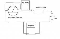
remove everything shown inside (resistor , cap , diode_
solder coil wires to output terminals/screws and close it
make test circuit by attached sketch , start with maximum value on trimpot, fiddle with trimpot to get full tilt of needle , then write down current and voltage
after that we have all data needed to implement it anywhere
solder coil wires to output terminals/screws and close it
make test circuit by attached sketch , start with maximum value on trimpot, fiddle with trimpot to get full tilt of needle , then write down current and voltage
after that we have all data needed to implement it anywhere
Attachments
- Home
- Amplifiers
- Pass Labs
- Pass lab meter