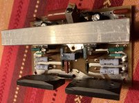
Mtx thunder 2301 output inductor

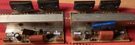
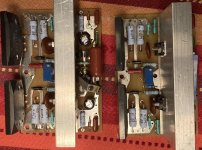
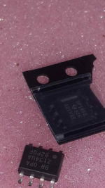
Ok so i got 2 of these 2301 amps i bough broken. After some parts around, i got 1 working. The second one had blown ps fets, gate resistors, ps drive transistor resistors, a shorted diode that i think the factory installed inplace of a rail cap and the inductor seemed to have some heat damage and a prior attemp to repair.

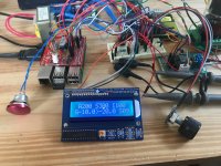
I got the amp to idle, even tho it was running hot and producing sound. Well here is were my problem starts.

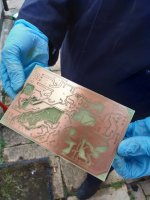
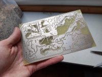
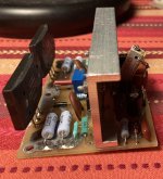
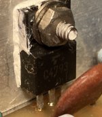
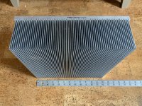
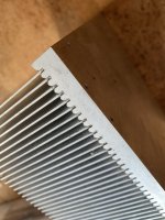
The output inductor had previously been messed with. It showed signs of overheating. Before powering the amp i took it out and compared it to the working amp. First thing i noticed is that it was installed incorrectly as if it got turned 90 degrees. I checked it for shorts between the two windings and it checked ok. Due to the burned wires, i had to cut some wiring and unwrap a turn on each winding. Checked for short and it was ok, even tho i don’t know for sure if the individual windings are shorted within themselves.
Went ahead and installed it and the amp runs a bit warmer then the other one.

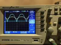
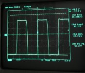
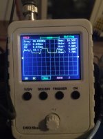
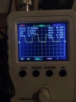
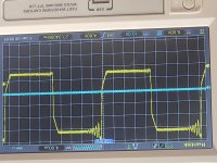
Here is were it gets weird. The amp produces sound both on the scope and with a load connected. Clean and no issues up to about 8 volts ac on the wave. Any higher then that and i see the wave start to break up(not clipping). The output wave soon dissapears, the fans try to turn on and the amp starts to draw more current. I havn’t measured the current draw, but i can hear the power supply fan slow down a bit, and voltage drops to about 8.5 from 12.5.
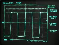
Here it gets pretty weird. I’m testing the amp with a sound generator app. I noticed that the higher the frequency, the lower the output of the amp before it (glitched). If i use a tone bellow 15hz i was able to get 35 volts of clean output before it started to clip. And the fan was running full speed like it should with full output. As soon as it increase the frequency, i hear what sounds like a hizzing sound and my output wave drops out. I didn’t noticed any dc on the output.

Finally broke down and pulled the inductor from the other amp and put it on there. The amp runs cold and i can get full clean output in all frequencies.

Now for my questions, what are my options with this output inductor? Is this typical behavior of a shorted inductor? Did me and the previous repairer removed enough turns from the inductor to make inefective at higher frequencies. I’m considering re-winding the inductor, but i don’t want to un do the working one to measure the wires. I do not have ways to measure inductance (that i know of). Any advice? I’m doing this mainly to learn more, so i want to know the how and why.

Thanks for the help.
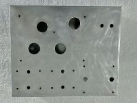
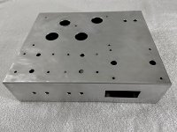
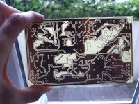
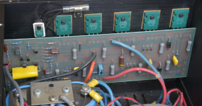
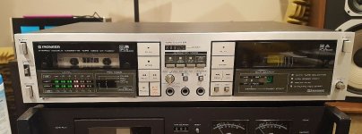
I’ll get some shots of the amp and the inductor here shortly.

Modded 4s Universal pre

Since I now have time to catch up on all the things that needed ... time.


I am no EE, far, far from it, but I am trying to learn at least some basics. My eyeballs hurt from constant staring at the computer screen. A couple buds at diymidwest helped me bunches building a 4s Universal tube preamp 4S Universal Preamplifier for 12A*7 Tubes. The build is here. 4s Universal tube pre — MAC/DIY While it allowed much tube rolling, it was pointed out how it was 'one size fits all' and while it might be optimal for a few tubes, for most tubes it probably was not. To that end, I was urged to optimize the 4s Universal for a single tube. The 12au7 it is.

Since I am but a newb, the cap/resistor values were suggested to me by the place I buy almost all the tube stuff, and moving the volume potentiometer to the input was suggested by everyone. This is the before and after. First diag is the original 4sUniversal, modded is number 2. After adding the 250k. of the potentiometer and 2.2k. stopper, I did not have the correct size smaller resistor to get exactly a 1m. grid leak so I had to put a 1m. in there.

First time ever doing a load line so this may not be correct, but if it is, the resistor/cap values may be way off.
For the load line, B+288v/82k+1.2k=3.46ma
For the cathode load line 2v/1.2k=1.67ma and 6v/1.2k=5ma


Way down in the lower left-hand area you will see Light green;load line, pink;cathode load line, and darker green;operating point. Also extended the cathode load line past -11v, which is the half-way point between grid voltage curves-22v and 0v. For a center bias, isn't this what I should be aiming for in an audio preamp? Using -11v as center bias and 288v yields the blue line, which I'm guessing is approximately where the load line should be?

Attachments

  • diy diagram.JPG
    diy diagram.JPG
    70.7 KB · Views: 403
  • diy diagram2.1.JPG
    diy diagram2.1.JPG
    50 KB · Views: 399
  • 12au7 loadline2_1.jpg
    12au7 loadline2_1.jpg
    323.8 KB · Views: 378

Visaton Grand Orgue subwoofer

Hello!
Refer to Visaton Grand Rogue website, the speakers can use as standalone subwoofer.

GRAND ORGUE | Visaton

"The bass part of the GRAND ORGUE, on its own without the full-range drivers, connected directly up to an active source without a passive crossover, acts as an excellent subwoofer and can be used, either singly or as a pair, to support music-orientated high-end loudspeakers and full-range loudspeakers down to the lowest bass frequencies and give home theatres the bottom end that they deserve."

Can I build the Grand Orgue as standalone subwoofer by removing those full range mid and high section? So which part should I remove based on the attached drawing?

Attachments

  • c9efa93f0e98667e91f1c8db597a31cb_540x.gif
    c9efa93f0e98667e91f1c8db597a31cb_540x.gif
    65.7 KB · Views: 288
  • caf150e9517d0caf3baade5e4ee7688c_540x.gif
    caf150e9517d0caf3baade5e4ee7688c_540x.gif
    88.9 KB · Views: 266
  • c10177bb1df375ec0de225c8cdad2826_540x.gif
    c10177bb1df375ec0de225c8cdad2826_540x.gif
    68.4 KB · Views: 291

Parts for a portable BT speaker, missing FR driver

Hello Everybody!

Looks like this is my first post on the forum, although I have had my share of diy projects in my life.

20200317-160155.jpg

20200328-165439.jpg

Although I just finished a home BT speaker(2x faitalpro 4fe32, tpa3116), I feel it is missing in the sub/bass section. Thus, I decided to build another BT speaker, this time PORTABLE!

Until now I have ordered almost all of the necessities, but I am still missing on the high frequency section drivers. What I have ordered:
1. Sub driver: GHXAMP Speaker 4.5 inch Bass Subwoofer Loudspeaker Mid bass Large Rubber Composite Aluminum Basin 4OHM 90dB 50W for Peerless|Combination Speakers| | - AliExpress
(I started off with the TB w3-1876s but ended up ordering this one. Cheaper, higher efficiency, approx. same volume required for a box. See the apple homepod)
2. 26650 3,7v accu for power bank. (6)
3. BMS 3s 40A for the accu. 3S 40A BMS 11.1V 12.6V 18650 lithium battery protection Board with balanced Version for drill 40A current/ Motorcycle battery| - AliExpress
4. 12v power plug: DC099 5.5 mm x 2.1mm DC Power Jack Socket Female Panel Mount Connector metal 5.5*2.1 5.5*2.5|Connectors| | - AliExpress
5. white led power button: 1pc 12mm Metal Push Button Switch High Head Ring/Power LOGO 3 220V Self reset Momentary/locking Waterproof Car Auto Eng|Switches| | - AliExpress
6. 12,6v 5a charger: Liitokala 12.6 V 5A power 12.6V charger for CCTV battery 5A charger for 12V 12V 12V battery 12V battery charger|Chargers| | - AliExpress
7. heat shrink tube for power bank.
8. DC-DC converter for constant voltage on the amp: https://www.aliexpress.com/item/32963683426.html?spm=a2g0s.9042311.0.0.27424c4doXV1OT
9. bluetooth receiver with IR remote: https://www.aliexpress.com/item/4000813876859.html?spm=a2g0s.9042311.0.0.3fb84c4dDdj3jN
10. 2.1 preamp/divider for audio signal: https://www.aliexpress.com/item/32773087353.html?spm=a2g0s.9042311.0.0.3fb84c4dDdj3jN
11. YDA138 amp board x3: https://www.aliexpress.com/item/33059299045.html?spm=a2g0s.9042311.0.0.3fb84c4dDdj3jN
(I decided on this board just by looking on the datasheets of some power amp ics able to run off ~12V. I ended up with tpa3110 and YDA138 and went for yamaha one https://pdf1.alldatasheet.com/datasheet-pdf/view/205149/YAMAHA/YDA138.html / http://www.ti.com/lit/ds/symlink/tpa3110d2.pdf)

NOW, I need the high frequency drivers.
Starting off at the Apple example with the 7 HF drivers, but without the processor, I thought I could go with 8x 1inch 16ohm paralelled drivers per channel. I am now pondering what to do, what to choose from:
a. 8 pieces of https://www.aliexpress.com/item/32817199763.html?spm=a2g0o.productlist.0.0.635776d0SaQ6OX
b. 2 pieces of https://www.aliexpress.com/item/4000029127816.html?spm=a2g0o.productlist.0.0.55671b77BVk6Ch
c. 4 pieces of https://www.aliexpress.com/item/4000027091657.html?spm=a2g0o.productlist.0.0.7bbd4db8cYXelT
d. 4 pieces of https://www.aliexpress.com/item/33041383465.html?spm=a2g0o.detail.1000060.2.6de0acb308rv3a
e. 2 pieces of https://www.aliexpress.com/item/4000272833081.html?spm=a2g0o.productlist.0.0.8b001b771qkx1u

The housing I think I will build of plywood, vertical cylinder, down oriented woofer and BR ports, and the HF drivers will be mounted on the upper cylinder wall.

Now, what do you think about the parts, and what do you think I should chose as HF drivers? Fell free to chip in with an idea 🙂

Thank you.

Willow II

I could not contain the excitement any longer and had to share the fruits of my labours over the last 7 months.
Willow II Born.jpg
It all started with me contacting Robert Nance Dee the designer of my previous build consisting of his PI and Willow I.
He mentioned he had been working on a new design for a preamp the Willow II and it was due to be published in the February 2016 edition of Audioxpress magazine. He then generously asked if I would like to be a tester for him and have a go at building it! When a great designer asks that you cannot say no.
I had no idea what I was getting into and Robert loving minimalist builds, this was all SMD!
He kindly supplied me the PCB's with a BOM and off I went ordering all the parts I was so excited. I'm going to do a complete build of this preamp later on but just to create interest and show what is possible.
Willow II Born 2.jpg
And yes it is Arduino powered!

Help with 2.5/3way simulation

Help with 2.5/3 way

Hi friends,
After debating about a good quality 2way many people suggested going 2.5way. After research and a lot of thought what makes more sense is to keep my floorstanders, and make them sing.

The floorstanders are made by morel but the original drivers were cheap quality. I tried sb acoustics sb16pfc25 and sb29rdc and even with the morel crossover, which is way wrong since the SB16 drivers are 8 ohm and sb29rdc 4ohms (morel woofer/mid was 6ohm and Tweeter 8ohm) the sound is much better.

The mid driver is at a separate 12 liter sealed box and the bass driver is at a separate 35 liter reflex box
The front baffle measures at 20cmX94cm
The configuration is woofer-mid-tweeter

Here is where I need you guys to step in.

I can do it 2.5way. In that case should I cut holes at the wood that separates woofer and mid in order to unite the volume for both drivers?

Should I keep it 3way adjusting the crossover to the new drivers and keeping the separate volume for mid and woofer?

A friend who has experience, simulated the 2.5way as is(separate volume for each driver) and get these results. What do you think of his design?

Going 3way instead of 2.5way with 6inch midbass drivers, does it makes sense?

Attachments

  • FB_IMG_1591357578591.jpg
    FB_IMG_1591357578591.jpg
    112.9 KB · Views: 153
  • FB_IMG_1591357542425.jpg
    FB_IMG_1591357542425.jpg
    25.2 KB · Views: 148
  • FB_IMG_1591357548170.jpg
    FB_IMG_1591357548170.jpg
    27.6 KB · Views: 144
  • FB_IMG_1591357554358.jpg
    FB_IMG_1591357554358.jpg
    33.1 KB · Views: 145

Six Year SSE Project Nearing Completion

Hey everyone,
On 4/14/2014 I purchased a Tubelab SSE board from George.
Well, I've finally gathered every last part I need to to finish this project!

For me, by far the biggest hurdle - so far - was the chassis. My hobby budget doesn't permit a custom fabricated job; I had to go with a $36 Hammond and do all the cutting myself. Using a stepped bit, various files, and sandpaper I ended up with a chassis I'm happy with. I intend to paint it tomorrow with self-etching primer and textured paint (too many imperfections for a smooth, gloss finish).

Here are a couple of photos...

Attachments

  • chassis-02.jpg
    chassis-02.jpg
    341.9 KB · Views: 487
  • chassis-01.jpg
    chassis-01.jpg
    324.7 KB · Views: 477

Grounding

I am going to build a 30watt, PP, 12BH7A/6L6GC amp from the book "Vacuum Tube Amplifier Basics" by EJ Zurich. This design is a mono block, but I'm converting it to stereo. My only concern is the grounding scheme. The author uses many 3 & 5 lug solder terminals, which is fine from a neatness standpoint. However, all grounds, both power and signal, are strictly through the ground lugs on these terminals. There is no starpoint. I've read that ground wires provide a much better return path than the chassis alone. Is this something I should be concerned about?

Passive Analog Summing Mixer Design Review

Hey everyone, I'm a recent graduate from electrical engineering and I want to start working my way into the audio field.

I want to create a passive analog summing mixer with 16 balanced inputs and 2 balanced outputs to use in my personal studio. Basically all mixing and panning is done ITB, summed through this mixer, and then amplified by a mic preamp to make up for the attenuation loss. It's a simple concept and a very easy design for me to take on since this is my first.

I'm not very concerned with the schematic design or functionality, but I have little to no experience creating PCB layouts. Especially in the audio realm where things may be done differently. I was wondering If someone could take a look at this layout and review it and offer suggestions/improvements.

Some general questions I have:
Grounding. I've seen a million different opinions on what to use, and I have ZERO expertise on the subject (star vs plane etc.). Would one of these be better for my specific design? How do I implement it in the most effective way? If I can use ground plane (like I am currently), what area should it cover?
Routing. The dualport dsub killed me. Is it ok to use multiple layers in a design like this? How could I improve my routing? Is 10mil okay for trace width?
Are the placement of my connectors ok? (CAD is not my strength, and I want to be able to use an enclosure properly)

A few things to note:
I want all connectors to be rear facing, so there will be some unavoidable black space (upper right). That's ok with me.
I want to use the dualport dsub connector for the inputs in order to save the most space, even though it makes routing a nightmare.

It honestly blows my mind that I can go through 4 years of electrical engineering and have zero experience working with any kind of PCB design in classes or labs. Thank you for any help, suggestions or ideas, it's been nearly impossible to find this kind of info anywhere.

Attachments

  • Schematic.PNG
    Schematic.PNG
    102.6 KB · Views: 639
  • PCB1.PNG
    PCB1.PNG
    152.2 KB · Views: 621

NEW VIDEO: AKAI GX-747 How to replace tension arm belts

Hello Guys,

This is my first post and wanted to share this video I made on replacing Belts on the AKAI-747 Reel to Reel I hope someone finds this video useful.. looking forward to future participation in this forum.

If you guys have any questions for me make sure to ask here or on the video comment.. thanks...


https://www.youtube.com/watch?v=WVtDHB4iOjk

Pass Labs B4 crossover questions

Hello,

I am hoping to find out about the Pass Labs B4 crossover I have heard about.

Is this available for sale yet? Price?

I am hoping to find out some technical details of this unit if anyone can share about it.

I read about prototypes being in the field a few months back but haven't heard much since.

I was hoping to find out if it offers level adjustment for using different sensitivity drivers/amps.

I also am hoping to find out the crossover points.

Thanks for any help you can provide.

-Nick

Selling my Dennis Colin Phono Preamp Kit

This is Colin's Groove Master design: JFET input and ultra-low distortion AD797 op amps. Excellent full-sptectrum noise figure, headroom and RIAA precision. Kit consists of partial kit: 2 manuals (user and assembly), parts list, JFETS and circuit board. I'll include 14 .05% resistors that I bought for 7 important locations (in each channel).
Anyone interested?

Technics SA-5250 Transistor Replacement

Hello Everybody,


today I got a broken Technics SA-5250 Receiver. One Channel was dead. The Power Amplifiers are mounted on Cards, removing one Channel revealed the right channel to be dead. The Drivers and Power Transistors seems to be dead, Collector-Emitter-Short. The Supply Voltage is +-30V.
The Drivers are 2SC1567 and 2SA794. I'd like to substitute them with BD139/BD140, their Vce is lower, but I think 80V is still enough for +-30V.

The Power Transistors are 2SC1667 and 2SA837. For these I don't have a 100% fitting replacement, but I've found two pairs of really old looking 2SD551 and 2SB681, which should be fine, but I'm not quite sure about that. MJ21193/MJ21194 should be fitting too, but I'd have to order these ...


Maybe someone could verify my decision, so that I don't fry more transistors.


Thank you very much


Lukas

Gunderson compensation..

What do y'all think of Steven Gunderson's approach?

Note that this is the technique used by Rotel in their RB1090 power amp., and Randy Slone in his designs.

Also available as:

'A Topology to Linearize Miller-Effect Compensated Amplifiers'

JAES Volume 32 Number 6 pp. 430-434; June 1984
An additional topology to Miller-effect compensated amplifiers, which reduces high-frequency distortion, is described. The addition is implementable in discrete or integrated circuits, with little or no additional complexity required in designs incorporating short-circuit protection. This topology is effective in reducing distortion to frequencies greater than 10 MHz. The greatest effect is achieved in power amplifiers with push-pull output stages.
Author: Gunderson, Steven J.

3D tube curves using an el'Cheapo tube tester

This may belong in the 'Test Equipment' section, but I thought I might share a 3D graph of a 6CA7 transfer curves I measured. There is beauty in it's simplicity!

I put together a concept tube tester based on a RPi and Microchip PIC to make these measurements. (Total cost without the RPi screen and anode transformer is about USD 80). Total measurement time (for 6500 data points) was 40 seconds, excluding tube heating time.

The original purpose of the project was to build a self contained tester that was not tied to a laptop/computer, that was fast, let the tube reach normal operating temperatures (ie not pulsed), but still gave full access to the raw measured data so it can be manipulated with Python script.

Attachments

  • Screenshot from 2019-07-20 14-04-49.png
    Screenshot from 2019-07-20 14-04-49.png
    313.9 KB · Views: 634
  • IMG_2196.JPG
    IMG_2196.JPG
    827.8 KB · Views: 656
  • IMG_2193.JPG
    IMG_2193.JPG
    710.5 KB · Views: 622

PCB making - first attempt

Hi,

I just wanted to share the results of my first attempt at PCB making.

The board is for a headphone guitar amp and I designed it using EasyEDA. I printed the layout onto tracing paper with a Samsung M2026 laser printer. I made two copies and overlaid them to increase the contrast. I actually had to print several copies to get two that were the same size. It seems that the printer isn't 100% accurate each time.

I used a Bungard pre-sensitised board and exposed it for 6 mins using a MEGA UV exposure unit. I then developed the board in sodium hydroxide for about 30 seconds and then etched in ferric chloride for about 15 minutes. After cleaning off the photo-resist with acetone, I tinned the board in 'seno tin' tinning solution.

I couldn't be happier with how it turned out. I spent a long time reading posts on this forum and in other places to try and avoid making mistakes so I wanted to share my exact method and results in case anyone, like me, is thinking about making PCBs but is worried about how difficult it might be.

I've still got to drill the board, so that's the next challenge, and then see if it actually works! Fingers crossed.

attachment.php


attachment.php


attachment.php


James

Attachments

  • PCB_1.jpg
    PCB_1.jpg
    304.3 KB · Views: 478
  • PCB_2.jpg
    PCB_2.jpg
    316.1 KB · Views: 783
  • PCB_3.jpg
    PCB_3.jpg
    390 KB · Views: 529

Alpine MRV1507 fault

Hi all, wishing you all good health at these testing times.

I have an Alpine MRV1507 on the bench, it's pulling excessive current a few seconds after applying remote power.

I've tested the power supply and although it's had a previous repair it powers up and idles fine if I disconnect the 6 pin molex which connects to the output board.

All the output transistors also test good.
Q819 has been replaced with a 2SD600 which had a loose solder pad which I have resoldered.

Initially it would power up then trip my power supply after 8-10 seconds, now it trips within a few seconds.

Any help appreciated, thanks

Positive power supply rail at a different potential than negative rail?

Further to my poking around inside a Sony XM 6020 I have discovered that the positive rail potential is ~33% lower than the negative rail's potential to ground.

The positive rail measures at around +22 v whereas the negative rail measures at -32 v.

I have noticed that the filter capacitor on the negative rail is also warmer than the capacitor on the positive rail.

The spec given in the service manual is +32/-32 volts.

The voltages at the drains of the mosfets just before the transformer are identical.

The square wave taken from the anodes of the rectifiers seems to be "offset" low, if that makes sense?

Is the problem in the rectifier diodes, it seems unlikely to be the transformer isn't is?

Attachments

  • Sony XM 6020 PS schematic.jpg
    Sony XM 6020 PS schematic.jpg
    246.8 KB · Views: 267
  • D88C7CD1-9B26-453A-9CAD-80935F389E8F.jpg
    D88C7CD1-9B26-453A-9CAD-80935F389E8F.jpg
    559.3 KB · Views: 243
  • 67D80BA4-AACC-45B3-BBE2-E554A7750BCA.jpg
    67D80BA4-AACC-45B3-BBE2-E554A7750BCA.jpg
    552.1 KB · Views: 224

Building a two way bookshelf

Hi all,

I am thinking to build a pair of bookshelf speakers using Scan-Speak 8" woofers and probably some aluminum dome tweeters from Seas, Vifa, Morell, or any good quality brand. I can build the crossover myself but prefer to buy a kit to assemble it. I have not idea what cutting frequency should I get since I don't know too much about these drivers. For what I have read, these drivers will work cutting them to 2000hz, 2500hz, 3000hz, 3500hz and 4000 hz. (two way crossover)

This is a project I want to do for fun and entertainment but I would like to have good results. I am trying to get advice from those who already has built DIY speakers or know the best way to chose a crossover. I don't know if it could be a good idea to cut the tweeter high and let more mid-frequencies to reach the woofer or to cut lower the tweeter allowing more mid-frequencies going to it. I am toward to allow more mid-range going to the woofer but I may be wrong. I think the woofer handles the mid better than a 1" metallic dome tweeter.

Please, give me some light about how to chose the crossovers and correct me if I am wrong with it.

Thanks

DIYSG Fusion 12's & 8 Center, Yamaha RXV2700, GSG 21" FM boxes, Pr. Dayton 10" subs.

DIYSG Fusion 12's & 8 Center, Yamaha RXV2700, GSG 21" FM boxes, Pr. Dayton 10" subs.

Got some stuff taking up room since my last build.

A pair of DIYSG Fusion 12's with pre-assembled Xovers, plus a Fusion 8 Center. All in black Duratex in excellent shape. Quality binding posts. $500 for the set.

My Yamaha RX-V2700 7.2 AVR. Excellent 1 owner condition. Beast of an amp at 140w/channel. Comes with both remotes, YPAO mic and a suitable box. $200.

A pair of GSG Audio 21" Full Marty flat packs on a pallet. Bought 4, but 2 is more than enough for my room (or my house for that matter). $500 for the pair. Local pickup only (less than half of my total to have them shipped to my loading dock).

I'm open to selling my completed GSG 21" Full Marty boxes filled with the B&C 21" 4 ohm driver finished in Duratex. $1500 firm...local pickup.

A pair of Dayton HF 10" 8 ohm subs in 1 cft sealed boxes finished in Duratex.
Again, excellent condition with binding posts and feet. $old for the pair.

All items built or owned by me since new. Obviously prefer local buyers and would make a great package deal. Would consider shipping but we would have to work out the details Pics available....just let me know. I'm in southwest Missouri and occasionally get to KC, St. Louis, Tulsa so a meet up is always possible. Ebay feedback is Huskerpilk. Sold a few things on AVS forums.

Thousands of vintage NOS film(mostly polyester) caps for sale or trade

Hello, I have here a massive collection of good film caps. All are new and still have long leads. The vast majority are 0.22uF with the rest being .2uF, .18uF, .16uF and .15uF and only a few being other, close values.
These are all good brands like ITW, Wesco, Acu-Cap(Aerotech), Mullard, Sprague, Epcos, Rel-cap, El Pac, Paktron, G.E., EC, Nytronics, ITT, Hopkins, IMB, TRW, Panasonic and Conrel Dubilier. Some of these like the v161-456 and Rel-caps I only have less than a dozen of each. Others, I have nearly 100 and a few, and like the Epcos stacked caps, the blue ITWs, the Wesco(Northern Telecom) and Sprague orange drops I have hundreds to thousands of.
I don't need all these, especially so many being the same value. I need to get rid of them so no reasonable offer will be turned down.
What I am looking for in trade are some capacitors for a couple gainclones I am working on. I need some good electrolytics that are at least 50v, some 0.1uF polyester caps, and some good input film caps with values of 1.0uF up to about 4.7uF.
I will ship anywhere in the US or even abroad. I prefer trade because it makes things easier not having to deal with paypal but if someone would like to buy a quantity I am open to the possibility. I am fine with shipping mine first and then the other party can ship when when they know their order is on the way.
Here are pics showing one of each type of capacitor I have available. The left side starts at 0.20uF and goes down to 0.15uF. The right side is all 0.22uF. There are also a few pics of the whole collection.
Have questions or want to make me an offer? Please message me or post here. Thanks

Attachments

  • 2020-06-05 17.26.46.jpg
    2020-06-05 17.26.46.jpg
    518.1 KB · Views: 275
  • 2020-06-05 17.30.04.jpg
    2020-06-05 17.30.04.jpg
    781.5 KB · Views: 279
  • 2020-06-05 17.42.43.jpg
    2020-06-05 17.42.43.jpg
    918.8 KB · Views: 271
  • 2019-09-27 06.58.45.jpg
    2019-09-27 06.58.45.jpg
    931.4 KB · Views: 248
  • 2019-09-27 06.59.18.jpg
    2019-09-27 06.59.18.jpg
    748.6 KB · Views: 246
  • 2019-09-27 06.59.24.jpg
    2019-09-27 06.59.24.jpg
    748 KB · Views: 120
  • 2019-09-27 06.59.37.jpg
    2019-09-27 06.59.37.jpg
    808.1 KB · Views: 115
  • 2019-09-27 06.59.48.jpg
    2019-09-27 06.59.48.jpg
    758.6 KB · Views: 100
  • 2019-09-27 06.59.43.jpg
    2019-09-27 06.59.43.jpg
    785 KB · Views: 98
  • 2020-01-30 01.56.05.jpg
    2020-01-30 01.56.05.jpg
    427.7 KB · Views: 134

Hum issues- Lehmann audio black cube linear

I own an original Lehmann audio black cube linear that has recently started a hum issue.
I know this headphone amp has been cloned many times so am hoping someone familiar could help me troubleshoot.

The symptoms:

When I touch the volume knob I get hum. Both in the headphones and the line out

The hum is louder at high volume and worse when set to high gain settings

When I touch both the volume knob and a grounded part of the chassis such as the RCA connector the hum reduces or goes away.
It does not matter what amps/dacs are connected. The problem is persistent and only if I touch the volume knob.


Where do I start? What could cause this to start occurring after so many years?

Thank you for the assistance.

Boston Acoustics RC61LF Parameters.

Hi,

I'm looking to build an enclosure for this old set of Boston Acoustics RC61 I have pulled out of the basement.

Have the two mid base drivers, the tweeters and the crossover.

Does anyone know what the Thiele parameters of this driver is? Cant seem to locate online, and Boston Acoustics responded with my request that "Unfortunately the driver parameters are not available"

Thanks!

Full digital Class-D amplifier on FPGA (with a multibit sigma-delta noiseshaper)

Dear all,

I implemented a new Class-D amp which is modulating the PWM signal fully digital with the help of a 4th order noise-shaper.

So actually a similar concept like a lot of silicon vendors out there are using for their digital I2S input Class-D amps.

The full source code is available on my GitHub:
GitHub - YetAnotherElectronicsChannel/FPGA-Class-D-Amplifier

And I also explained everything once again in a YouTube video (including listening tests)
YouTube

Have fun by checking out,
Markus

Krell KAV300CD Player mods

I have a Krell KAV300CD player, that I really like and I am looking for some cost effective mods to improve it's performance. I have recently had it serviced with a new laser, and I will be re-capping it in the near future. I also heard that an improved clock can make a big difference.

There are many options out there, does anyone have any suggestions? I've been looking at the TentLabs XO, but I have no way to compare the various offerings out there.

Any and all suggestions are welcome!

Crossover help for Delta 120A-Celestion-Beyma T 2030

Hello friends, this is my first post and i really need your help.I have just finish my new speakers with 1 x woofer eminence Delta 120A ,2 x midrange celestion TF0615MR(close back) and 2 x tweeters Beyma T 2030.I have a big problem with the crossovers, can you help me found out what crossover should i use for it ? I use an old crossover from my previous speakers but the result is terrible.I cant use the softwares -i dont understand those-is there someone who can design a crossover for me and what componets should i use? I am given you specs from the drivers :12" Woofer
400 W RMS,8 Ohm,54 Hz - 5 kHz 6'' midrange 97 db, 8 Ohm,50 watt rms,500-5,000Hz Tweeter Power: 15W
Impedance: 8 Ohm
SPL: 95dB / W / m
Extremely high quality high-end tweeter from 2.5 kHz Thanks!!!!!
An externally hosted image should be here but it was not working when we last tested it.

Hertz hp1d full rebuild

Full rebuild.

I've already removed all the FETS in the PS section and the Output section.
All dead.
Output driver board for the class D is still in place as I have to fix the PS section first.

I've checked the gate drive in the PS just before the gate resistors (as this ones also have to be replaced).

I don't think this is normal. Two of the banks driving one of the transformers look shifted upwards. The other one looks normal. Pictures attached. So I think i will have to rebuild also the PS board - i think it is the buffer driver transistors.

Attachments

  • other side.jpg
    other side.jpg
    235.8 KB · Views: 196
  • one side.jpg
    one side.jpg
    224.9 KB · Views: 192

Anyone interested in making a gerber file for me? I'll pay!

Is anyone interested in making a gerber file for me? I'd be happy to pay if it means I don't have to master the software out there.

I've looked at EasyEDA and a few others. I'm sure they are wonderful programs ... if you do PC boards on a regular basis and take the time to master the software.

This a a very simple board, I can send an "old school" drawing with all the components, traces and labeling.

Any recommendations on where to have a small quantity of boards made up? I have talked to JLCPCB. Prices are great but would like to try someone in the states. I also talked to RUSHPCB, they were about 10 times more expensive than JLCPCB. If that's the case with all USA made boards, I'll look abroad.

Lastly, is this the right form for this post? It's software related but I'm giving up on the software and am looking to hire help!


Thanks,

Eric

4" to 5" speaker suggestion for fullrange MLTL build with some more bass??

I have already built 2 TABAQ pairs (MLTL which are very similar in dimensions) and now I am hooked... Now almost any simple bass reflex commercial speakers up to 500EUR with that rubbery bass sound flawed to me.

Your advice is needed for another build. I feel ready for bigger and a bit more expensive, requirements to make it more narrow suggestion:

  1. Finished speaker has to go a bit deeper than TABAQ, lets say that 10Hz lower is ok, especially some more bass in 40-50Hz range.
  2. Decent quality of treble at 10-14kHz. I really understand, that full-ranger will not be as crisp as dedicated tweeter, but midwoofers acting as full-ranges is not to my liking. I am deaf above 13.5kHz, so the very upper part does not matter.
  3. 4-6 inch full-range speaker. 3 inch and smaller excluded. Preferably with as little correction filters or equalization required, but this is not deal-breaker. Price per one driver up to 80 USD/EUR, if there is smth head and shoulder above everything else - can be 100USD/EUR per unit. It should be available in Europe. Probably I am still not ready for MarkAudio, so exclude them for now...
  4. Speaker type - MLTL or other similar quarterwave type designs. The sound of them really impressed me, also space is limited. The only exception could be compact front firing horn if it has any advantages to MLTL.

With all above, what you, dear DIY colleagues would suggest me? Is it WIBAQ sized speaker with some cool but cheap driver I want to build?
I am not afraid of Hornresp anymore, so will simulate anything you will suggest me 😉

All suggestions are appreciated! Thanks in advance!

FS: Jean Hiraga 20W class A amp boards.

FS are a pair of NOS finished calibrated and tested Jean Hiraga 20 W class A amps. Good way to try out the amp without the hassle of building it and optimizing it. Price $140 for the pair. Two more pairs are available. These were only used during dial in which required mounting them on the heatsink and connecting them.
Modern Toshiba and Sanken (genuine) semiconductors were used. A high precision trimpot was introduced for fine tuning. This is a plug and play board and gives a few mV DC offset on the output. The PCB was redesigned for short signal path and large vias with custom C-channel heatsinks for excellent thermal stability. The +/- supply, ouptut and ground are designed to be screwed on the wire crimped loop terminals. The inputs are solder on.
All that is needed is a CRC-type power supply and a good enclosure with plenty of heatsink. They were setup to match the original Hiraga 20W bias numbers, approx +/-20 V rails and 1A bias. The components are barely breaking a sweat.

input pairs: toshiba 2sa1016/2sc2362
drivers: toshiba 2sc4793/2sa1837
output: sanken 2sc2922/2sa1216

Attachments

  • IMG_5063.JPG
    IMG_5063.JPG
    452.3 KB · Views: 272
  • IMG_5064.jpg
    IMG_5064.jpg
    596 KB · Views: 292
  • IMG_5066.jpg
    IMG_5066.jpg
    719.8 KB · Views: 281
  • IMG_5060.jpg
    IMG_5060.jpg
    547 KB · Views: 281
  • IMG_5065.jpg
    IMG_5065.jpg
    547.2 KB · Views: 272
  • IMG_5062.JPG
    IMG_5062.JPG
    657.7 KB · Views: 189
  • IMG_5058.jpg
    IMG_5058.jpg
    882.6 KB · Views: 160

Amp for Stax electrets - 5687 outputs?

In a fit of boredom and in the knowledge that there are some sources of sockets to plug them into, I have been pondering what it would take to make a DIY OTL amp for my Stax SR30 electrets.

The specs for these are 95dB at 100V input, impedance at 10kHz of 150kohm (although there is obviously a capacitive element) which makes it look like an OTL design based around a valve used for driver stages could work. From what is in the parts bin, it looks like 5687s in push pull could work?

I've atttached a schematic of what the initial back of a packet thoughts are, using 10M45 CCSs as I have had good results previously and it seems to make sense in the context of the output stage requirements. This would presumably lead to an effective loading for the 5687s of 75k each?

The first stage is currently a bit of a throwaway (as I am aware that there are some views on the actual quality of ECC82s...) to show what sort of first stage gain would be required for a reasonable output. In any case, I am not yet sure whether this would go in a system with a balanced preamp or not.

So before anything more goes into the design such as operating point tweaking, are there any points of complete idiocy that I have failed to spot in this context?

Attachments

Consensus on SMP's for indirect heaters (assumption is you want DC heaters)?

I know this is an old subject, but... I was at Axpona last year and saw a tube phono pre-amp for sale in the $8,000 range, it used dual SMP's for the heaters! I've seen posters here who regularly use SMP's for indirect heaters. And for B+. Assuming someone does want to use DC... These off the shelf Meanwell supplies are just so dog-gone economical at ratings up to 29A! One would be tempted to just use them and save a lot of time.

No 6 volt units here but plenty of 12 and 24 volt where you could series connect like tubes as stereo pairs or quads. Using proper construction, distances, wiring, etc. Is there some absolute reason to not use a drop in an SMP module for an indirect heater? Or is it all opinion? Is the parasitic really that problematic?

line card:

MEAN WELL LRS Power Supplies Application and Features

Example supply:

LRS-100-12: MEAN WELL : <p>102W 12V 8.5A Single Output High Efficiency Power Supply</p> : Power Supplies & Wall Adapters

Sorely tempted by small PPSL

Hello all,

I am sorely tempted to build a small PPSL for my living room / car.

I was thinking of 8" or 10" drivers to keep it super compact, hopefully with a room / car F3 somewhere around 30hz. (not winning any SPL contests I know!)

Had anyone got any good leads for drivers? Keen to keep the cost below £200 if possible! I have had a quick look at car drivers, but unsure which to trust to be honest. Happy to sim in WinISD.

Power will be a TAS5630 @ 50v (140@8r, 240@4r) in home, unsure about car..

Many thanks in advance,

i need help with Stage Master circuit

Hi all, i'm making the Legend Stage Master amplifier of Dr. Jagodic but i have some strange behaviors.
I'm an experienced electronics builder so, i think to have made all at good level and i already have checked many times all the circuit without find any evident problem.
In attach you can find the circuit of the amplifier.
To be prudent, i did the first power on with 17-0-17 supply and the result are:
1. The output is at + 16V
2. Probing the gate of the mosfet of final stage i found 16V for the positive rail and -17V for the negative.
3. The trimmer to adjust the offset make the adjustment only from 16 to 14V.
4. The quiescent current, can be adjusted from 0.5mA to 6mA. Due the low supply maybe it's right but what about the offset ?
It's seems that the mosfet are working in saturation area but why ?
Could you please help me to investigate looking at the circuit ?

Maybe the supply is too low to engage the circuit ? it would be the first time, i made hundreds of amps and always did the first power on with a low supply like this. Always worked....but now ?
Please help........

Attachments

Marantz PM7200 input level issue

I'm using a DAC which is connected to a graphic equalizer and goes into my Marantz PM7200 amp. When I turn up the volume on the DAC, at 12 o'clock position the amp already starts to distort even on low volume. First I thought that the equalizer is the problem, as it increases the gain a bit too, but if I connect my Sony TA FE-570 it has no difficulty even with the DAC on maximum volume. What can be the case here, is my Marantz faulty or just has a lower input tolerance? (Both used on AUX input) Thanks.

3-Way Desktop Speaker Design

Hello all,

I'm looking to design and build a relatively compact but high end pair of 3-way desktop speakers. Here are a few general criteria I'm working with:

- The height of each speaker should be kept to a minimum (preferably around 5-6")
- I'll plan on using an active crossover and separate amps per driver (high performing class D amplifier kits / designs aren't that difficult to come across and this is my first project so an active crossover gives me a larger tuning window after construction to get things sounding pretty)

As far as driver decision goes, I've got my eyes on the following:

- Tang Band W4 2089 (this seems to give a pretty stunning of low end for the size)
- Dayton Audio RS100P-4 (well reviewed midbass/midrange covered by Zaphs testing)
- Fountek NeoCD3.5H (this might just be my technophile side telling me a ribbon tweeter would be fancy. I originally had the Tymphany XT25TG30-04 holding this spot)

I'm mainly looking for critiques on driver selection so far but anything else would be much appreciated so I'll list my ideas for cabinet design too:

- Since it's a desktop speaker, I figure I can run a transmission line from the Tang Band down and up behind the desk saving hugely on desktop space usage.
- The Dayton will probably be the vented configuration recommended on their website

Any criticism would be much appreciated! Am I insane? Are there better driver choices available for the money? Or am I going about this completely the wrong way?

Thanks all in advance!

SPICE MODEL MJL3281/1302 need to be repaired

844476d1589600880-spice-model-mjl3281-1302-repaired-soice-jpg


The spice models provided by Onsemi , cordell , Improved SPICE Models for MJL3281A and MJL1302A - Section 1 , do not work in time domain. The internal emitter resistors about 0.04 ohms , can see on datasheet Ic/Vbe function is also forgotten . Can someone help these transistors models work?

It works on LT but not on Tina. Any suggestions?

Attachments

  • soice.JPG
    soice.JPG
    158.1 KB · Views: 363

Forte Model 1 and Forte Model 3 Adjust Bias

I've read a few posts here about adjusting the Bias and I'm a bit confused on which resistors are the emitter resistors. I've attached a pic of the board. Can someone point out which is the emitter resistors and which posts I should get the meter readings from when adjusting?

See attached image. Ultimately, an arrow to the component would be helpful 🙂

Also, there is talk about replacing the pot for a 20 turn and this board has one I believe. Can someone send me a link to the correct POT to purchase? I've got a Forte Model 3 and a Forte Model 1 that I'm getting up and running.

thanks for all you do!

Attachments

  • forte3board.png
    forte3board.png
    579.2 KB · Views: 240

Help! TT, One channel not working

So, I spent all day rewiring the R200 tone arm on my Rega planar 2. I soldered the wires from the bottom of the tonearm into a DIN female, and made a new cable with a DIN male connection. Was a pain in the ***, but now the signal is constant. Buuuuuut the right channel still has no signal. Tested both lines with the multimeter and they come out perfect.
Tried swapping the rcas on my amp, amp is fine...

Any idea? It had this problem before, as well as general instability from bad wiring. Signal coming and going, etc...

Advanced issues in audio transformers.

Hi folks,

So far, I've been winding output transformers with one secondary tap only.

Recently, I started experimenting winding multitap OPTs, and now, with a Williamson style transformer secondary layer configuration, this is where trouble begins.

In my recent prototype:

The primary has 3650 turns, 20 layers.
Each secondary layer has 38 layers (38*3), trifiliar. There are 5 layers

So, logically, there should be the following impedances possible:
1. All in parallel - 74k / 8R
2. 76 turns - 18.5k / 8R
3. 112 turns / 8.2k / 8R
4. 152 turns / 4.6k / 8R
5. 190 turns / 2.95k / 8R

But..

When a series connection of secondaries is made, no matter the order, the series resonance of the coil drops by the double (from 70 to 35kHz) and I see no reason why it should, as the secondary is already low impedance. For this drop in Fres, there must be 4 times increase of capacitance or Ls. It's puzzling.

The funny thing is, different series connections don't influence the Fres. Even one series connection, for example 1//2//3 - 4//5 screws it all and makes no difference to "all layers" in series. The slightly satisfying news is, this resonance is quite damped, since there's no peaking with the intended source impedance.

Although it's not everything...
there is a severe dip following at 53kHz, which appears to be a parallel LC resonance, due to the fact the dip increases with source impedance. More unbelievable is the other fact this resonance, if really parallel RLC, is not depending of the main inductance.

Only parallel connection gives the best measurement, with the Fres of 70kHz. It also lacks the severe dip afterwards.

So I'm creating this thread with any hope to discuss this problem with someone who got already familiar with such issues. I see no reason why series connecting secondary layers should bring such a huge, downgrading difference. It would make sense for an interstage transformer, but on an already low Z secondary?

Proposed 3-way design - your recommendations?

Proposed 3-way design - comments/recommendations?

Hey fellow audio DIYers. newbie here. After 3 months of reading speaker reviews, endless pages of Econowave, dipole and horn design threads, I've decided to build my first pair of speakers instead of buying new 2-way bookshelf speakers for my apartment space. I figure for the same price I can do better.

Accordingly, I am hereby humbly accepting any constructive feedback from this forum's esteemed membership on my below overall design choices before I calibrate my table saw. Thank you in advance!

Objectives:
- medium loudness listening levels in a 16'x16' living room space, 8' high ceiling, music only
- desiring very good hi-fi low-upper midrange accuracy, clarity and balance for jazz, classical, R&B
- total audio components cost to be < $350.00
- will install pre-assembled crossover, not a custom-built crossover (because of job, kids and many hobbies time constraint)
- cannot be huge speakers (wife/GF speaker low dislike factor)
Overall design:
- 100-150W max power, passive, 3-way, floorstanding, 2 speakers only, no subwoofer planned
- committed to 12" woofer in bass-reflex cabinet (3.1 cu.ft.) - enclosure separate from midrange CD horn and supertweeter
- leaning towards a 1000Hz/5000Hz 8-ohm crossover and drivers
- going for controlled directivity with a midrange 1" compression driver horn - so far decided on a JBL JRX speaker waveguide clone like the ones used in the Econowave designs (rated good for down to 1000Hz, and with very minimal "colouration" as I understand it), eg., Dayton Audio H6512 6-1/2" x 12" Waveguide 1-3/8"- 18 TPI
- will order drivers and components from Parts Express and/or other recommended suppliers
- maybe prudent to install L-pads for midrange horns and supertweeters?
- construction: 3/4" MDF well braced cabinet w/ thicker front baffle made of MDF and maple or walnut veneer plywood exterior, internal sound dampening material is still TBD
Specific components:
- woofer, midrange 1" compression driver and supertweeter choices - still TBD
Existing audio path:
- mp3s, flacs on laptop/HDD --> Schitt Modi DAC --> 1990's Yamaha 60W/ch receiver--> speakers
- better hi-fi 100W 2-channel integrated SS amp planned for near future
- to add switchover tube amplfier option/experimenting in 5+ years

See included 2D frontal scale diagram of speaker design for your reference - this is how I would envision it.

So, what am I forgetting or should be considering? Or recommendations from anyone who has built a similar 3-way? And yes, I have reviewed the "So you want to design your own speaker from scratch!" thread.

Happy listening to all. 🙂

Attachments

  • speaker1.jpeg
    speaker1.jpeg
    52.1 KB · Views: 663

What are my options? Purchased 12AU7/ECC82 to replace 12AU7/6922EH in Bravo Audio v2

*Please let me know if I have posted this in the wrong place*

Hello,

I have created a little problem for myself and I'm wondering what I can do to make use of my mistake.
I'm very new to tube amplifiers, and had a Bravo Audio v2 that I wished to upgrade.

When I looked online, I believed the consensus was that the "12AU7" is also known in Europe under its Mullard–Philips tube designation ECC82, and that these tubes were interchangeable. I also saw that Bravo Audio themselves sold a variant of the V2 with a Golden Lion ECC82, so I assumed I was good to go on buying this type of tube.

I know now, after purchasing a TAD RT005 Tube 12AU7 ECC82 that this is not the case. I found this out by plugging it in and only getting signal from one channel.

I know, I'm probably the biggest idiot for doing this, but I would like to know if there's anything I can do. I have a lot of experience working with circuit boards; is there any modification I can make to the Bravo Audio v2 to make it accept the 12AU7/ECC82 tube?
If not, what's my best course of action? I'm finding it very difficult to find an answer, which is no doubt because of my lack of savvy on this topic, but I would appreciate help. Even just a basic explanation to why and how I messed up would be much appreciated.
I'm finding it hard to find an upgrade amplifier that takes this tube too.

Apologies for the dumb post but I couldn't find anywhere else to ask for help.

Glenn

Small Thor - which XO?

Hi all,

believe or not, it's taken me more than 10 years to finally take those Millenium and Excel speakers off the shelv in my basement and build some Small Thor enclosures for them. I had built original Thor (or rather Hobby Hifi's Evo 04 modification) back in 2003 or so, but when I read about the new enclosures here in the forums I crashed those new boxes and wanted to build new ones. Well, that went quick... 🙂

I know you've all probably moved on to different speakers and are already bored by the Thors, but I'd need some help with the XO. I want to build Jim's improved version, but there are many schematics flying around those threads and I can't figure out which one is the patest and greatest. I managed to find

From https://www.diyaudio.com/forums/multi-way/64799-clarity-seas-thor-kit-post2838726.html:
https://www.diyaudio.com/forums/att...as-thor-kit-reduced-baffle-step-crossover-jpg

From https://www.diyaudio.com/forums/multi-way/64799-clarity-seas-thor-kit-post4541052.html:
https://www.diyaudio.com/forums/att...ty-seas-thor-kit-excel_lr4_crossover_1500-jpg

From https://www.diyaudio.com/forums/multi-way/64799-clarity-seas-thor-kit-post4851083.html:
https://www.diyaudio.com/forums/att...as-thor-index-threads-excel_lr4_crossover.jpg

Is there any chronology to those? What are the differences in terms of sound? Any help would be greatly appreciated!

Thanks, Hauke

Brand New HI-VI Research 8" Kevlar Woofer F8Ba

Just listed 6/7/2020 on eBay for 10 days a new HI-VI Research 8" Kevlar Woofer F8Ba. Please have a look if you are interested.


Cast aluminum basket provides stability
Rigid Kevlar cone for improved clarity
Shielded design can be used near TV's

This handsome woofer features a black Kevlar non-woven fiber cone, rubber surround, and massive cast aluminum frame. Very similar to the standard F8 woofer, this driver provides the same smooth frequency response and very dynamic bass. Specifications: *Power handling: 120 watts RMS/160 watts max *VCdia: 1-1/2" *Impedance: 8 ohms *Re: 6.50 ohms *Fs: 32 Hz *SPL: 89 dB 2.83V/1m *Vas: 1.76 cu. ft. *Qms: 4.59 *Qes: .37 *Qts: .34 *Xmax: 5 mm *Dimensions: A: 8-1/2", B: 7-1/2", C: 4-1/4".

Pioneer Tape Deck CT 1040W - LEFT DECK "B" Motor Stopped Moving :

Hello All :


So today i noticed that the motor is not moving but rest of the mechanism is all good with current. I have no clue what caused that? i was working just fine a few days ago. The other DECK "A" is all fine as well. Some help please. I have attached the service manual with the diagrams for the geniuses to look at guide me with solution please.

Service manual link:

Gofile

PS: I don't think if there are any dried solder connections/traces ... who knows 🙁

Attachments

  • Pioneer CT-1040W.jpg
    Pioneer CT-1040W.jpg
    153.9 KB · Views: 134

Tascam CD-401 MKII Belt

Hello everyone,

I try to repair a Tascam CD-401 MKII which had a broken belt, and it has been removed before I could measure it. I didn't succeed in finding a new one on the Internet, does anyone know if it is the same belt on other Tascam models or the dimensions of the CD-401's one ?
As I have ever build a belt for a turntable from belt sold by meter, I think that I could do the same with this one if I have the proper dimensions (diameter and lenght).

Thanks.

External power supply , safety earth and ground lift

I have a power supply in a separate metal enclosure for use with low voltage audio equipment. the chassis is earthed via a standard 3 pin connector (earth connection). The idea of the project is for this PSU to connect to separate modules (each in their own metal enclosure) via umbilical cords. The PSU has regulated ±20V + earth output(s) (i.e. '3 wire umbilical).
The '0V' line is to be ground lifted:
  • Should the ground lift be in the main PSU or in each individual module?
In respect of 'safety ground':
  • Should the safety ground be connected to each individual module (i.e. a '4 wire connection') from the main PSU?
I would guess there would be no benefit of adding a ground lift in an external module if there's no safety earth connection to the module anyway (?).
Each external module will have it's own internal ± 15V regulator (hence running the main PSU supply to the modules at ± 20V).
  • One of the modules will be a phono preamp which will require an earth connection to the record player as well.
  • The second module is a standard preamp/volume control
  • The third will probably be a DAC.

BTW I had a spare enclosure, ±18V/160VA toroidal, hefty voltage regulator and some nice power connectors (male and female) lying around so I thought I'd make use of them instead of the expense of separate PSU's for each module.
Also only one 'power button' required on the external PSU to power up all modules and one mains connection. 😀

Many thanks!

Soldering 0.5mm pitch footprints.

Had some fun soldering some 0.5mm pitch footprints.
Had some mixed results to start with and found some pads shorted or some not making contact. So on my next pcb I put a line of vias down next to each pin so I could test for shorts and open circuits.

For soldering I was sticking down components with paste flux to hold it in place.
So long as I pressed it well down through the flux it sort of worked OK.

I then watched a youtube video where he cleaned the pads and that worked well. So tried it on one of my PCB's and the soldering worked much better.
I put a little liquid flux on the pads then rubbed it with some kitchen paper towel. The pads then soldered much better.

I found running the soldering iron on the pads back and forth added more solder between pads and pins and looked much better.

Thank goodness for reading glasses and a magnifying glass to check for shorts.

Solstice MLTL from Parts Express

Hi, has anyone built or auditioned the Solstice MLTL kit from Parts Express? I'm really interested in purchasing these as my first DIY speaker project. There's only one review on the site, and my googling hasn't turned up any real hands-on reviews of the finished product. That makes me a little hesitant to pull the trigger, considering the price ($500 per speaker).

Harman Kardon 6600

It looks like it's been since 2011 that anyone posted about this amp. I'm trying to fix mine. Relatively new at this but a background in EE that's not completely useless. The problem I'm trying to address is that one channel cuts in and out, mostly out. Starting with adjustment of bias voltages and some difficulty already. (the measures drift when the speaker switch is off- they seem to be stable if it's on, but the manual says to have it off). Anyone able to advise? Many thanks-

Drop-in replacement for JRC4558

I bought a car dvd recently. Everything is fine except ... the sound quality. For fun, I would like to upgrade the JRC4558 chips (and TDA7338 probably) on the circuit board to some better ones to see if there's any improvement. My question is, is OPA2132U a good drop-in replacement for it? What's the difference between OPA2132U and OPA2132UA?

Also, it seems there are many other chips that I could use, e.g. OPA2228, OPA2134, etc. Which one is better?

Any suggestions are welcome! Thanks!

Doubling crossover’s value

I have a pair of woofer and its crossover networks. I obtained a pair of the same. I’d like to make the dual-woofer system. So, I put a pair of them in a cabinet. Since the driver resistance is low, approx. 3.6 ohms each, I wired them in series connection. The impedance now is about twice of the original, says 7.2 ohms. The original crossover is simply a 2nd order. So thing I have to do is to double the value of an inductor and a capacitor? Is it right? Thank you in advance

Class AB Hexfet Amp Temperature Compensation.

I've been working on an old International Rectifier design from Ap Note AN-948.

Link: http://www.cieri.net/Documenti/Altr...ifier Using Complementary HEXFETs (AN948).pdf

The following semi's were used. Q1, Q2 ; 2N5087. Q4 ; MPSA06. Q3 ; PN2222A. Q5 ; IRF630 Q6 ; IRF9630

The following changes to the schematic: R10; 220 Ohms, added gate stopper to Q6, 220 Ohms.

Source resistors added to Q5 and Q6, 0.22 Ohms 5W.

Q5 and Q6 are on a common heatsink with Q3 held face down between them. Initially Q3 was not touching the heatsink. At 28.3C bias was set to 0.45V across the two source resistors, ~ 102mA. At 56.5C the bias current was 68mA. After I made a little clamp to hold Q3 to the heatsink, the change in bias was worse. At 31.5C bias was 116mA and at 56.8C it shrunk to 47.7mA.

Looking into things further, the Q6 gate to Q5 gate Voltage was 7.83V at 100mA (at 28.8C) and shrunk to 7.13V at 43.2mA and 53.3C. While the heatsink was at 53.3C the bias was adjusted to 100mA and the gate-gate Voltage measured 7.67V.

Note: The above measurements were made without disconnecting the 4 Ohm dummy load so load current could have corrupted the idle current measurements.

Two solutions come to mind. First, insert a stable Voltage in series with the Vbe multiplier like a TL431. It looks like the TL431 needs to be 5.075V and the Vbe multiplier at 2.755V so that the temperature coefficient of the multiplier matches the output MOSFETs.

Second, use a small MOSFET like an IRF510 as a Vgs multiplier. Not sure if this will work because the current in the Q4 is only 5mA.

Has anyone tried these solutions or come up with something else ?

Help! Philips CD80 dead MCU

Help! CD80 gurus. I forgot to plugin the front panel 8-pin data cable when power on the CD80. Then I made a stupid mistake, without powering off, I just hot plugin the data cable. Now I believe the MCU is dead, there is no display, and the turntable motor keeps spinning once power up. I measured the RESET pin (pin 1) of MCU (marked SC409017P P115), it's always 0V, even if I disconnect the front panel data cable and power cable.

Are there anything else I can do to troubleshoot? Does anyone know any low end CD player has the same 68HC05 MCU P115 version I can pull MCU from?

Many thanks!

AYA II Kit / Power Transformer

Checking if there is an interest in buying a AYA II kit (the PCB was fully assembled with all the parts by Audial) + Power Transformer. I purchased this kit directly from Pedja (not thru the GB here on diyaudio)

Apologies for the scrappy enclousure - I put together what I had at the time until I got around buying a proper enclosure - but that never happened :sigh:

This DAC has truly stood the test of time and even to this day has given a good many DACs a run for their money.

Asking USD 525 + shipping. I will cover paypal fees.
IMG_4246.jpeg

IMG_4245.jpeg

IMG_4243.jpeg

IMG_4247.jpeg

Anybody know "Trio" oscilloscopes/tone-generators?

When I was a child I remember not being able to sleep because my farther was testing amps and loudspeakers using a tone generator......

Forty years later I am in a similar situation - the audio hobby is genetically heritable!

Recently, I have dug out the equipment used by my farther including an oscilloscope (Trio CO-1303D) and a tone generator (Trio AG-202A). Knowing my farther he would have bought the "second-best" so maybe this gear is still useful besides the emotional value.

The units works perfectly when powering them on after 30 years of disuse. My idea of recapping the oscilloscope unit was a bit discouraged after opening the unit - everything is wired/soldered so carefully that disassembly will be very complex.....

Advise or opinions anybody?

Cheers,
Nic
Projects by fanatics, for fanatics
Get answers and advice for everyone wanting to learn the art of audio.
Join the Community
507,771
Members
7,887,703
Messages

Filter

Forum Statistics

Threads
406,194
Messages
7,887,703
Members
507,771
Latest member
denengineer