Stereo Amp with Speaker kit into one pair of speakers

I'm a beginner so please be kind and straightforward.
Building a Bluetooth Speaker from a kit but only using one Woofer and Tweeter.
The kit is a C-Note bookshelf speaker (stereo) and the Amp is a Dayton Audio KAB250v3. So the amp has 2 sets of speaker leads, but I will only be using one tweeter and woofer. I have built the crossovers, but want to know how to wire the speaker from the Amp without causing any amp damage. Should I just pair the -ves together and do the same with the +ves or do I need to build a stereo/mono converter? thanks! Tom

FS: 2x 5m + 1x 2m TriAmp twisted pairs speaker cable

3 ways twisted pair speaker cable

* OFC - Copper Silver Coated Stranded
* Teflon insulation
* Conductor size (4mm²): 1 (for the tweeter) + 1.3 (for the midrange)+1.6 (for the bass)mm²
* Plug amplifier side: Mundorf Banana plug Beryllium
* Connector speaker side: 2x Neutrik SpeakOn per speaker; easily adaptable to Bananas ectr.

I used a 5m and 2m cable set. These are also fully assembled. With the second 5m cable the Speakons would have to be transferred from the 2m cable.

100.- EUR plus postage insured DHL shipping within EU (& GB)

And as always:
Private sale, warranty and exchange excluded.

Naim NAPA Transistor Question

Hi all,

I'm fixing a pair of NAPA boards from a NAP250 and need to replace a BC239C due to it having a broken leg. I've searched around and have found advice about replacing the long tailed pair with BC546s, among other things, but nothing detailed about the original BC239Cs.

In regard to the BC546s, the advice I seen in multiple places is to ensure that the transistor used for TR1 has an hFE at least 5-10% greater than that used for TR2, with similar values across the pair of boards.

I have read also that BC239Cs used for the long tailed pair need to be 'matched', to keep dc offset in the preferred range, but can find no detail about that process. Does anyone know whether the objective of this matching is to get as close a match, in terms of hFE, as possible or, as with the BC546s, to aim for a target delta between TR1 and TR2 ?

I would like to stick to BC239Cs, to keep the board as stock as possible.

Thanks for reading; any help would be appreciated.

Cheers,
Bo

Poor man's bench PS

I'd like to put together a bench power supply for my ... "experiments". I don't really need regulation. I've got a little pile of filament transformers for 2.5V, 6.3V, and 12.6V. Planning to put all of them in a chassis with banana sockets. All the transformers for each voltage are identical, so I'm just going to parallel them. Each voltage will have its own fuse and power switch. Maybe a switchable doubler to get 5V from the 2.5V units.

For B+, I'm considering picking up a Hammond AO-32 power supply. Pretty cheap on eBay. It's got a massive PT with a 415/0/415 winding, a 2.5H choke, and a filter cap can. If I use diodes instead of tubes and bypass the choke, looks like about 525V with 150mA load. I'd run it through a variac to achieve lower voltages - manual regulation. About $40 for a used 120V/2A panel-mount. Maybe also have a switch to swap the choke for additional filter caps.

Does this sound reasonable?

Advice for 10 channel amplifier

Good Evening

I am looking a wee bit of advice please.

It is my intention to build a 10 channel amplifier. Each stereo channel is about 170 mm in width and 90 mm in height.

The following chassis comes to my mind.
Dissipante 5U – diyAudio Store

Is it possible to squeeze three of these PCBs on each side based on the
40 mm heatsink 200 mm * 210 mm?

Please advice.

Thank you

Yeshu26

Which 6SN7 preamp should I build?

Hi Everyone,

I'm about to build a 6SN7 preamp for use with my SS amp. I have found two schematics that look promising.

One is a schematic by Frank:
http://www.diyaudio.com/forums/atta...tamp=1092149935

The other I got from a friend. My friend's circuit is SRPP, and having just read an article on tubecad.com, http://www.tubecad.com/may2000/ where it says...

"It [SRPP] is often misused as a line stage amplifier (where the load impedance is not predefined) or as a driver stage (where the load impedance is far too high). Preloading the output overcomes much of the mismatching problems. Preloading means adding a fixed resistor to the output a value slightly higher than optimal, so that when an external high impedance load is added, the combined paralleled impedance will prove optimal. Still the question remains: if the load to be driven is a high impedance one, why bother with a push-pull output stage? If high gain and a good PSRR figure are needed, use a current source loaded Grounded Cathode amplifier instead. If low output impedance is needed, use a White Cathode Follower, Plate Follower, Cathode Follower, or even a lower rp triode instead. It is often misused as a line stage amplifier (where the load impedance is not predefined) or as a driver stage (where the load impedance is far too high)."

I have my doubts. Frank's schematic seems the way to go. The problem is that I'm listening to my friends line-stage as I type this, and it sounds very good.

What would you reccomend?

Thanks, Chris.:scratch:

Attachments

  • 6sn7 schematic.jpg
    6sn7 schematic.jpg
    64.2 KB · Views: 8,244

Kairos Crossover

R Hi everybody.

I have SB Acoustic Satori MW16P-4 (4ohm) and the TW29R Satori tweeters. I was using these in my car and have since removed. I am now looking to build the Kairos Kit from meniscus. however crossover will need to be changed. I am looking for assistance on new crossover for these speakers utilizing the enclosure from the Kairos. Any help would be appreciated, thanks.

crossover question for a sub

Hi all, I'm good at putting wheels on things but crap at electronics.

2UFQUvc.png


This is mk I of an object I intend to build,

a subwoofer on wheels

with outdoor JBL control speakers (8ohm)

and an Alpine PDX 2.150 2 channel amp capable of

[2ohms @14.4V 1%THD]: 150W x 2
[4ohms @14.4V 1%THD]: 150W x 2

ikd05JR.png


link here

The subwoofer is 2 ohm. Its a pioneer TS-WX205.

The speakers are 2x 8ohm. I intend to wire the speakers so that they are 4ohm.

I was informed on this forum that the amp can drive a 2 ohm load on one channel and a 4 ohm load on the second channel and not die. So thats nice.


So this is what I want to do.

I need to find a 2ohm low pass filter for the sub, but that is not an easy thing to find.

b10wTeJ.png


I read a bit, but I'm not naturally good at this stuff.

Is it true that I could use a 4ohm low pass filter at 160Hz, and because it has a 2ohm load, it will actually filter at 80Hz ?

Altec 353A input selector wiring

I am helping a pal of mine with his partially gutted Altec 353A. The input selector switch was removed when he received it.
He just wants a simple line selector on there to select 6 inputs. I have a 6pdt rotary switch that would be great. He is using primarily phono, and line level sources. All interface with the RCA inputs on rear of unit.

Im having a heck of a time making sense of the original rotary selections for the Section 3 Rear Deck.

Without these localized feedback networks, the amp is unusable with regard to line noise.
Can anybody throw out some ideas for taming this beast.
Here are the 2 scenarios:

Phono source impedance.

Line level 1v type input.

I've tried to mock up (clip in) what I'm able to follow and the noise reduction is there, along with signal reduction too. But it's not right. My test source currently is my phone audio sent to RCA ins. The parts wired onto the RCA jacks themselves stand (phono) but that deck with the feedback elements are not present, and I'm seeing double from staring at em and trying to decode what switches in/shorts with the deck of the switch. I attached a link to the schematic and a zoom of the area in question. Any basic pointers would be great! Thanks.
https://2.bp.blogspot.com/-4Df_rARe8Xc/V_CnQszSX2I/AAAAAAABaAo/WtphxNDKofEVyTYcVlaDyigwHzWtgpdIgCLcB/s1600/altec%2Blancing%2Bpower%2Bamp%2Bvalve%2Btype.jpg

Attachments

  • IMG_3147.jpg
    IMG_3147.jpg
    72.6 KB · Views: 181

FS [US]: Nord Three SE Purifi 1ET400 MKII Mono Blocks in Silver

I had these Nord mono blocks for just a few months since April and they are in mint condition. Bought directly from Nord new - built to order.

These amps are based on the Purifi 1ET400 modules, one of the best class D amplifier available today. They run cool and are extremely transparent producing vanishing levels of noise and distortion.

Binding posts are WBT 0703Cu.

Also included is a set of 4 Sparkos Labs SS2590 op amps. You can swap the op amps at the input stage for a small amount of customization. Installed are the Sonic Imagery 990Enh.

Asking Price: $2300.00 + $60 shipping (US only)

PayPal only. Local pickup available in Northern NJ, Montclair area.

Kenwood DP-3300D DAC

Long story short, I bought a Kenwood DP-3300D CD player after I saw some internal pics of the beast. Seems very well design and constructed with what appears to be top of the line stuff all around.

TBH I dont listen to CDs, mostly I play records or stream music. For the later I was wondering to use the DP-3300D DAC portion of it by adding a Coax digital input and put the DAC part to good use.

Can some body more knowledgeable give me some north if it is possible & worth it, and if so...where to start. My DIY experience is more in the analog /solid state than in the Digital realm.

Attached is a pic of the DAC board in question and a brief description (found online)
-One per channel Burr-Brown PCM56P DAC (high-spec ‘K’ versions)
-4 per channel NE5532 opamps
-Fixed / variable output

Cheers,
Rob.

Attachments

  • Capture.JPG
    Capture.JPG
    48 KB · Views: 315

Single output OPT for 4-8 ohms speakers

This is a mental exercise at the moment, say I want to build a 300B SET on the cheap. I'm aware that 300B and cheap don't go well together.

Say I want to use Edcor OPT, and of course they come with only a single output. And let's say that despite that I insist on using them to drive speakers ranging from 4-8 ohms.

Is it better if I go with 3k:4 ohm OPT while using 8 ohm speakers?

Or go 5k:8 ohm OPT while using 4 ohm speakers?

In my research, someone hinted that one in theory is better than the other in terms of bandwidth, but I'm not informed enough to take the hint. 😀 So, someone please enlighten me.

Two identical speakercabs - different drivers, how bad?

Soo I was doing my thing here some time ago, and blew up some speakers. I had built two speakers using 4x 18sound 10nw650 drivers + bms4594 horn, and I had a couple of unconcious noob seconds where I turned some knobs that I should have left unturn, and I blew all the woofers during tuning.

I have recone kits for two of them, but delivery time for the other ones is over a month, and I have an event coming up in a couple of weeks. Now its time to be creative and break some rules, I need to ask how bad my ideas are.

I am quite limited in options in norway, the event is creeping up in the speed of light, so I have to choose from drivers which are in stock. What would be the consequences if I use the reconed 10nw650s on one side, and put in Fane Sovereign Pro 10-300 in the other one? Cabs are 47liters and tuned to 57hz, but will cut them around 105hz. I will attach the sims of acoustic power and phase. Black line is 18sound, grey is Fane Sovereign. How bad is this idea? So bad I should definetely buy 4x new drivers, or acceptable?

Thanks in andvance!

Attachments

  • acousticpower.png
    acousticpower.png
    61.2 KB · Views: 167
  • Phase difference.png
    Phase difference.png
    54.7 KB · Views: 163

An Unorthodox and Affordable 1st Class System

(Updated 8/26; see end of post)


This is a description of a DIY stereo system which comprises the unlikely combination of fairly powerful desktop computers, common surround-soundcards, modest chip amplifiers and large, efficient loudspeakers. I'm posting to explain how, using very affordable techniques, I built what I consider a theater-quality stereo system. It's lounging here because no other forum appears general enough.

This DIY hi-fi project, now about six years old, evolved from a simple attempt at providing FM background music for my fairly large cave into a main focus of my attention. It grew from analog basics into an analog/digital hybrid, then to several phases that were MiniDSP-based, and finally into a fully desktop-driven (minus power amps and speakers) system with large loudspeakers and very high output quality.

As such it has met several revised objectives besides presentation of music as realistically as possible. That part of course remains subjective, but a number of quantifiable goals help me get closer. They are
a. good definition and low distortion at all output levels
b. no clipping anywhere along the signal chain
c. lifelike dynamics
d. elimination of phase shift from source entry to drivers
e. a wide open software-driven platform (making the rest possible).

This is its current format. The entire thing could be assembled for around $2500 plus the requisite effort, as is.

1. Components

a. Speakers
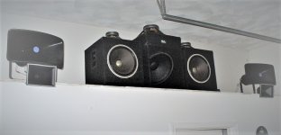
Loudspeakers are chosen for clarity, range, efficiency and dynamic capacity, along with durability, compatibility and affordability. Room decor is not a factor, though with rearrangement and some faux cabinetry the exact setup desribed (minus the sub perhaps) could be made so. Their cost was ~$1800, dominating the cost of the system.

Subwoofer (1): A Peavey 18" Pro Rider is mounted in a Seismic Audio 18" downfiring sub cabinet with internal crossover bypassed. The result is a tight, smooth and efficient subwoofer that functions nominally from 60Hz on down. Its basic purpose is to relieve the bass drivers of the longest-throw frequencies, as their xmax is limited.

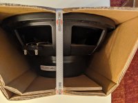
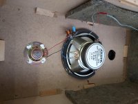
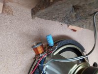
Woofer (2): Each woofer consists of a vintage Altec 421A mounted in a Seismic Audio 15" cabinet, again with internal crossovers bypassed. Each runs from 60Hz to 200Hz. The sound is pure Altec, tight and smooth. They are of course efficient. They cost ~$100 each used, were not recones, and worked perfectly.

Midrange (2): Each mid is an Atlas CJ-46 reflex horn loading an Atlas PD5VH driver, used over a remarkable 200Hz to 3kHz thanks mostly to the very long path length of the horn. The driver, rebranded, has been used as the mid driver of the Klipschorn. Despite its 'stadium' appearance, the horn/driver combo is clear and smooth and enables a choice of amazingly low high-pass points, which is what drew me to it. I frankly didn't expect it to work this well in a hi-fi application.

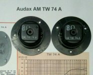
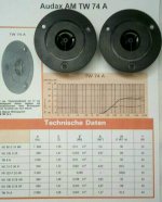
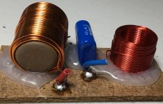
Tweeter (2): A Klipsch tractrix-hybrid horn, used recently in 'home theatre' speakers until replaced by a newer version and sold off at ~$35 each, has had its Klipsch driver replaced by an Eminence N151M-8 ring-radiator. An 0.47mF film capacitor is shunted across it to suppress residual RF from the class T amplifier, mostly to make scope readings clearer. Its minor effect on phase is compensated elsewhere in this writeup.

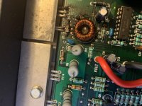
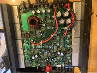
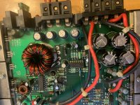
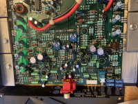
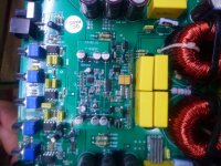
b. Power Amplification
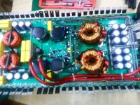
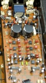
As the system is actively crossed over, each speaker is wired directly to its own amplifier. Two 1-unit 19-inch surplus rack mount boxes each house two Sure AA-AB32971 stereo boards and a switching power supply, each input run through a noninductive potentiometer for attenuation. The boards house either the Tripath ta2020 (clone?) or likelier the TI TPA3118. For various reasons it is hard to tell which is used (Newark specs the 2020 for their lot, PartsExpress the 3118 for theirs). I believe all mine are TPA3118, set at 770kHz switching frequency. They have low distortion and enough power to drive the speakers mentioned (including the sub) to very high levels in a large listening space without clipping. The four stereo boards cost ~$30 each, the two power supplies about the same.

c. Crossover
The crossover is housed in a refurbished HP 6300 ProDesk with Intel I5 quad-core (running Win10 up-to-date) and a simple Vantec PCIe 7.1 sound card (CMedia 8828 chip set), used for both optical input and multichannel analog output. Driver is provided by MS. Foobar2000 is the vehicle for the crossover. The computer cost ~$160 preloaded with Win10 Pro (updated once connected), the sound card ~$50. All apps and plugins used on the crossover end are freeware or donorware.

d. Front End
The front end, another HP desktop (as it happens, a refurbished Compaq Pro with 4-core AMD A8 5500B, also running Foobar on Win10) is used to stream external sources and play recorded sources off a fast M.2-type SSD. The machine lacks M.2 boot capability but the disk is mounted in a PCIe adapter for music storage. Another CM8828-based 7.1 PCIe sound card (Sedna) is used, despite only stereo output needed; this card is one of the few options these days for PCIe-based coax SPDIF output, which my data link requires. Hardware cost is roughly same as on crossover side, with one of the plugins (Mux Modular 7.4.4, an excellent graphic patch panel meant for DAWs) adding ~$70.
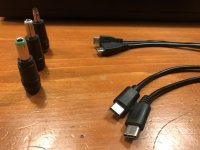
e. Data Link
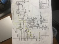
SPDIF is used to connect the two machines since a 1-wire solution is required for an optical connection to the crossover. This one is fairly unique though, and deserves mention. Were the machines close enough a simple cable (or even maybe a single computer) could have been used, but they are 40' apart, and the crossover and its DAC outputs must be near the power amps, which are near the speakers. Thus, a simple 74HC04 hex inverter based coax-to-optical converter was modified to drive a laser module instead of a Toslink output module and the very good 74HC04 changed to an even faster 74AC04. It is fed by coax SPDIF from the front end sound card. The modulated laser illuminates the open end of an optical cable connected to the input of the crossover machine's sound card. Tested to 192ks/s, used currently at 88.2ks/s, the final product contains about $40 worth of components.

2. System Setup
This is where the choice of fairly powerful desktops as a platform for the signal chain becomes apparent.

a. Front End
The purpose of the front end computer is to supply source material, process it and send it to the outside world as an SPDIF stereo signal. Foobar2000 is the vehicle of choice. Source material is kept on an M.2 PCIe-adapted NVRAM storage disk (except for that which is directly streamed from the web). This includes downloads, CDs etc., all of which are converted to FLAC for storage. The DSP stack has, in order,
i. Blue Cat's stereo gain module (to drop source levels ~8dB),
ii. Sox resampler to upsample for signal processing,
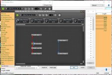
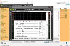
iii. Mux Modular, used solely as a wrapper for Reaxcomp which exhibits some instability in foobar otherwise. Reaxcomp, a compressor, is instead configured as a 10-band expander to restore dynamics, bands set from 40hz on up in octaves. The ideal would be of course one band per frequency, which is impossible for a number of reasons, but division into octave bands minimizes the dependence of a high frequency's expansion on a much lower frequency's level (since the former rides on the latter).
iv. Foo_convolve, the native Foobar convolution engine, which applies equalization from a curve built in RePhase (note foo_convolve seems to prefer stereo impulse files),
v. Sox resampler to match output to the data link sample rate, and
vi. Smart Dither set for 1 bit, 24 bits depth.

The output stage uses DS or WASAPI with copious buffering (latency is not a concern). A number of other (advanced) parameters are set to what seem optimal values (buffering, priorities etc. etc.). The resulting SPDIF signal exits the machine on the Sedna card's stereo coax output.

b. Crossover
Here, the CM8828 sound card is used on both ends, acting as default input on its optical-in and as default multichannel output on the 7.1 (analog) outs. Output is configured for 7.1 surround, perfect for a 4-way crossover with a single sub, all output channels set for full range.
The DSP stack of Foobar2000 is loaded with Sox resampler (to upsample for filter processing), ConvolverVST (to provide 8 filters), another Sox resampler (to downsample for the output driver) and Smart Dither. "Foo_record" plugin permits Foobar to play the default sound input (in this case the optical input of the Vantec). ConvolverVST needs more clarification. Besides housing 8 separate mono brickwall filters, its configuration text file also provides
i. 2-to-8 channel multiplexing and mapping for the outputs to the sound card,
ii. precise delay for each channel, critical in eliminating propagation delay from the loudspeaker array, and
iii. a variety of other things I don't use but you might like.

It is set on my machine to 16 partitions and 'patient' tuning (beware... you may have to set tuning one level higher during initial configuration to end up with 'patient'... it is a bit high-strung but worth the effort). Depending on filter size and tuning level prepare for a long initial optimization delay but a good deal less on each startup after the 'wisdom' file has been written to desktop (which it is every time foobar is closed smoothly). The author of the plugin recommends 'measure' tuning (one level lower than 'patient') and you may like the sound and appreciate the much faster optimization time.

iv. Amps
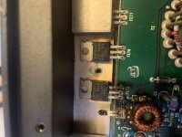
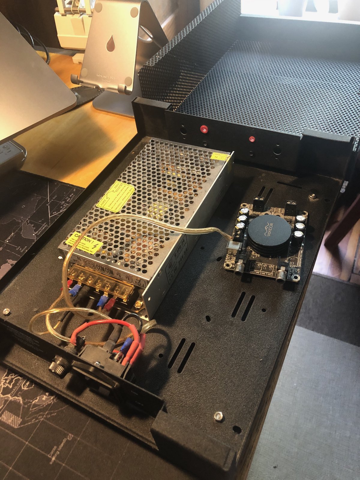
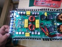
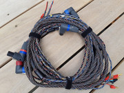
One could always leave the amp boards sitting around naked, but I like them mounted in a box. As mentioned, I use two 19" one-unit-height surplus rack boxes. Each fits two boards and one switching PS. Of course connectors, input attenuator pots, drilling, wiring and assembly are required. I suggest the use of cheap solid copper 'doorbell wire' for internal connections, which is overkill for conductivity and holds the shape you bend it to forever.

One last item: though the amp boards are fan-equipped, you may find the on/off cycling of the fans annoying. I suppress that by placing a 5" AC box fan atop each box over the cooling vents and controlling its speed with a small variac. It works even without air conditioning in hot weather. I also install the rack box tops with spacers to leave room for air entry/exit (and for the boards, which require more height than the typical 1 7/8" available on such rack boxes).

v. Drivers
Bear in mind when positioning drivers (esp. mids/tweeters) that unless you are bolted to a chair when you listen, parallax can affect phase relations on even perfectly aligned (on-axis) drivers. With a crossover point of e.g. 200hz and its ~5' wavelength this is a fairly minor issue. At higher frequencies, say 3khz, it becomes more important since the half-wavelength is ~2" and any repositioning of your ears that creates this small propagation deviation via parallax will result in cancellation. Note also that it's nice to have frequencies higher than the crossover point on the tweeter still in natural alignment with a fundamental tone on the mid. These realizations spawned a lot of 2-way and 3-way coaxial drivers decades ago, eliminating most parallax but still, in that day, with no way to compensate the offset voice coils of the close but still axially-staggered drivers.

Obviously the most practical alignment for separate drivers would be vertical and closely spaced, certainly for a mid/tweeter pair (unless your ears' elevation changes radically). Woofer/mid? Unless you are crossing over at >1khz, probably not an issue in most rooms. Woofer/sub? No issue (in this case 60hz and its ~20' wavelength make it a moot point).

You can correct for propagation delay and frequency-dependent phase shift in a variety of ways in software, but remember that this is true only for one listening point. Good driver alignment will help spread that hot spot pleasantly over a wider area, a good thing unless you don't mind lack of mobility.

3. System Testing and Tuning

a. Front End
Clipping avoidance is important anywhere on the signal chain. To this end, recordings are conveted to FLAC (to save space over WAV files while maintaining lossless conversion, and in the case of lossy downloads, to avoid further signal loss) using Alternative Replay Gain set to 'prevent clipping according to peak'. Sox upsamples to 384ks/s during this procedure, using an option in Replay Gain. Despite extant information indicating that Replay Gain must be set during playback for decoding, my testing indicates that the track is indeed moved below clipping levels with no decoding required at playback (indeed, the option to 'Remove ReplayGain Information From Files' is greyed out for files recorded in this fashion). All this is good for me since I haven't heard a limiter I like. I don't know whether this behavior is an artifact of using Alternate Replay Gain (which I do) or not.

The 'declipped' source material is dropped by 8 dB or so using Blue Cat's stereo gain (which tests phase linear on VST Plugin Analyser) since the next step involves dynamic expansion. Reaxcomp is my choice, carried within Mux Modular (itself a VST which tests phase linear) for stability. It is configured for 10 octave bands of expansion as mentioned earlier, the rest configured minimally with 1ms RMS size and 2ms release, attack and knee left at 0. Threshold is maxed at -150dB and ratio set at 0.88:1 (expansive). It is tuned on VST Plugin Analyser. Bands begin at 40hz. Phase is measured and minimized via manipulation of the per-band gain controls. It takes a while, but phase is constrained to +/- 1* over about 50% of the usable audio spectrum and +/- 2* over nearly the whole thing. 3* is never reached except at very low frequencies. For some reason distortion measurements come out best at sample rates of 128 or 256 ks/s (literally, not the powers of 2) at below -120dB THD/noise. I don't know if that's an artifact of the VST or of the test vehicle, but I currently use 352.8 ks/s as my processing rate. Reaxcomp has metering for checking input/output levels. Not knowing its format (RMS?), I try to leave about 6db of headroom on output for loud tracks.

A note about meters: RMS metering, while of interest to speaker and amplifier manufacturers, is worthless for this exercise. You need a fast peak meter. Acceptable RMS levels will do you no good when your cymbals, superimposed on a huge bass wave, are being sheared off.

Next comes foo_convolve, which carries the equalization curve. It requires no phase testing (VST Plugin Analyser can't test it anyway) as the impulse it processes is generated in RePhase as a phase linear FIR with 352.8 ks/s sample rate. RePhase offers a wealth of options for windowing, tap number etc. etc. Find what you like best. I use 256k taps (as the power of 2) with 2x the number of ffts (automatic in RePhase).

Note: the Sox plugin contains a filter but it is also a FIR which can be set to produce linear phase, and is perhaps bypassed by going to 99%(?). It will also suppress aliasing and imaging if so desired (certainly a good idea on the possibly base-changing initial conversion of source material).

Sox resamples back to 88.2ks/s for output to the sound card. Foo_dsp_dither (Smart Dither) is used as mentioned; it is optional but I recommend trying it (why not, it's free). And so we exit the front end without clipping, having done due diligence with various available peak meters. It is worth mentioning that foobar has a native peak meter under visualizations, operating at the output but not pluggable into the DSP stack. We also exit with darn near phase linear processing, the worst offender being the expander as mentioned.

b. Data Link
The data link, mentioned earlier, is fairly simple but details are beyond the scope of this document. Outdated descriptions are posted on the site and elsewhere. I'll update or rewrite it someday (I assume most would use either a cable or a single computer anyway).

c. Crossover
It is the job of the crossover machine to
* multiplex stereo input into 8-channel (i.e. 4 stereo channel) output
* map these channels properly onto the sound card
* host the filters that define the crossover
* correct significant amplitude and phase deviations endemic to the loudspeakers
* impart delay to each output channel to compensate propagation delay.
All of this is done by ConvolverVST via its config text file. Since there is only one subwoofer its two channels are summed to one for 7 actual outputs (also in ConvolverVST). Clipping avoidance and linear phase are of course as important here as on the front end.

The filters themselves are generated in RePhase as phase linear FIRs with the same number of taps and ffts as on the front end's loudness curve. Crossover points are 60hz, 200hz and 3khz. The filters are brickwalls. If a driver requires some equalization it is done with an overlay of the curve onto the filter. Moreover, since RePhase permits phase equalization, phase slopes are included in the mid and tweeter filters to compensate for measured deviations from linear.

Sox is again used to resample to filter rate (here 264600ks/s, or 6x44100), then again to output driver rate (88.2ks/s). Peak meters are used as in the front end against signal chain clipping.

As for measurement and testing, the following items require some work:
* cancellation of propagation delay
* compensation for amp/loudspeaker phase shift.

i. Propagation Delay
Audacity is used on the front end machine to manufacture a pure tone burst of the proper frequency, typically but not always a crossover frequency. It is fairly easy. Simply generate a tone with duration for perhaps 20 cycles. Use 'select at zero crossings' to find a proper cycle-start point someplace near the middle. Select 'track start to cursor' and zero the region with the 'silence' icon button. Now find another zero crossing, select 'cursor to track end' and zero that. If you are lucky you'll have a brief (e.g. 2 to 7 cycle) tone burst preceded and followed by silence. If you have a triggered storage scope (I don't) you can just play it once. Else loop play.

Place a microphone a short distance from the speakers. Any decent mike will do. Mine is dynamic, so I run it through a preamp. Scope the output of the preamp (or of the mike if you have an active mike). With a continuous tone you'd have no way of knowing if you were superimposing a later cycle onto an earlier one. This way you will know. Align the image by fine-tuning the delay in the ConvolverVST config file for one driver or the other so that turning up the (e.g.) tweeter produces a smooth amplification of the signal from the midrange (one good reason for input potentiometers on the power amps). Beware of artifacts from wall reflections.

Preface this entire operation by setting delays to ballpark figures using specs, a ruler or any other way of estimating the distances between the voice coils in question if you haven't already. It makes things much easier. If you use reflex horns, you'll need info on the path length, usually but not always accurate. It is inaccurate on my Atlas horn specs, listed as "4.5 feet" which seems to be a tech writer's misinterpretation of 45 inches (actually I measure 43" acoustically).

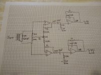
ii. Amp/Speaker Phase
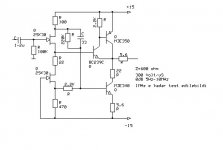
Tools exist for phase measurement using software and calibrated mikes (I have them), but the result, if you can get a reliable one, subsumes room effects and is valid at a single point. I prefer a perhaps less precise but more manageable electrical approach that leaves the room out. Tools required are
* a signal generator (again Audacity can be used; I also use my old Mercury tube generator)
* a scope (old BK 30Mhz used here, 100Mhz Leader available)
* one regular probe
* one differential probe (BK used here).

Most power amps have grounded input and floating output (coax input is certainly grounded to the device which feeds it). Since most 2-channel scopes have common ground, hooking one probe ground to signal input ground and the other to the 'minus' output terminal will ground the floating output terminal through the scope, producing anything from annoyance to complete disaster. Hence a differential (isolated) probe is used, typically on the floating output terminals (especially if you use a grounded outlet, which is a good idea).

Why am I measuring amplifier phase shift? Well, for starters, it is connected to the driver being measured (actually both are measured together, which is a bonus). Inductance meters are typically useless for this operation (used just on the driver). They tend to operate on a 1khz signal which is fine for a static inductor, but these inductors are part of a motor (damped AC solenoid?) which is subject to its inherent mechanical resonance and its load (horn, cabinet etc.). The impedance curve of any loudspeaker shows the former. Measuring that curve on a compression driver with and without horn loading shows the latter. We extrapolate that the mechanical phase follows impedance rather well. Thus we measure phase shift across the speaker (or amp, same node) terminals. Does this perfectly describe acoustic phase? Only if the speaker cone can rigidly track its own voice coil. But the correction made a very few incorrigibly bad-sounding songs (typically 60s Brazilian bossa novas) that I had given up on as poorly recorded suddenly quite listenable, along with making well-recorded songs better. It certainly improves things.

We send a signal to the driver at its high point (20khz perhaps for the tweeter) with the scope in dual-trace mode and sync from the input probe's channel. The phase lag, if one, will be visible as the output curve offset a bit from the input. Stretch the image, maintaining sync, until you have a long cycle length (say 40 divisions on-screen) and can measure the deviation of the output peak from the input to perhaps, e.g., 2 divisions. Now you have a ratio to apply to 360 and voila. Do the same at the low point (here is where you wish you didn't have a neo driver) and at a midpoint and interpolate. Rephase's paragraphic phase EQ will allow you to create an inverse phase shift in the tweeter filter. Do the same on the midrange. Woofers and subs are typically immune to huge phase shifts (mine were anyway) due to the low frequencies, some shift observed on the one driver tested past resonance. The more points plotted the better, but I find 3 to be adequate. Yet another advantage of the powerful little $30 chip amplifiers... a spare acts as test mule, making hookups quite simple.

4. Afterthoughts
The result of all this is a system that produces precise imaging, excellent definition and clarity, realistic dynamics etc. Moreover it can be tweaked, altered and augmented endlessly in software, DIY paradise.

i. A Note on Complementarity
For those who have seen this expression in the fine print of RePhase when generating brickwall filters, a simple test can demonstrate, or so I believe. Send a tone burst (in one of the ways described before) at crossover frequency to the crossover machine and simply scope the outputs of the adjacent sound card DACs, one on each channel (be sure you zero out your propagation delay compensation first in a copy of your ConvolverVST config file). Note that each waveform looks ragged. Switch your scope from dual-trace to 'add' or 'sum' and voila... they sum to a smooth burst. This effect happens even, e.g., on the lower-frequency channel despite the tone burst set 10% higher than the crossover frequency, an effect that diminishes as the crossover point becomes more distant. Thus it is important to have some driver leeway in your crossover points since each driver seems to have some work to do within its dead band. This effect is not clear (and perhaps does not occur at all?) with continuous tones.

ii. Why Expansion?
Dynamic expansion is something I've always liked. I built expanders in the 80s for my analog system. The problem being served is that most loudspeakers, microphones, anything mechanical, will impart some sort of compression to recorded sound. Additionally, much music is recorded with a lot of intentional compression for a variety of reasons. Playing through an expander (especially a multiband expander), properly set up, produces to my ears more lifelike sound.

iii. Foobar
Foobar2000 is a great platform. That said, it has many nooks for parameters to hide in. Under preferences/advanced, e.g., you'll find many things to tweak. That's just the beginning. I can't provide a foobar tutorial; I'm not the guy to ask anyway.

Also, you can start Foobar2000 at elevated priority (which I do) with a simple batch file in your desktop folder. For example,

start "foobar2000" /high "c:\program files (x86)\foobar2000\foobar2000.exe"

(assuming that's the location of your executable) will run foobar at high priority. Substitute "abovenormal" for "high" to run between normal and high.

iv. Why Would I Assemble a System Like This?
Good question, self. There are many reasons; here are some.

* In the 70s I bought a Mercury signal generator at Lafayette Electronics since I was suspicious that my much-hyped JBL L-100s didn't sound so hot. A simple manual sine sweep through all drivers at moderate power revealed frequency bands in each that buzzed badly. I tried replacing them with several other popular mid-end speakers. All of them were flawed. At that moment I (1) felt like a sucker and (2) became a fan of big woofers (Altec, e.g.) and horn mids/tweeters (Altec, ElectroVoice etc.). My living room system, made after purchasing my house in the 80s, was subjected to such testing. Its 15" Altecs have never failed. Neither have the Peavey compression drivers feeding the Altec 511 horns. The EV T-350 tweeters failed (due to a small decoupling cap in the crossover that shorted and sent a 100W pulse through them). The 'buzz check' is the first test any driver I buy gets. In the modern world, I find that even most inexpensive compression drivers are pretty robust. I retain a long-term ingrained fear of possibly (or even probably) fragile high-cost devices. Call it my 'sucker' complex. And I choose efficient drivers that can easily be driven today by chip amps, a vastly different approach to pulverizing bookshelf speakers (or emperiling directly-connected compression drivers) with superamps, once the only quiet option at idle. I know my chip amps won't clip at my levels, even on the sub, as they slip into white noise when clipping occurs. And they are quiet at idle, not easy with direct-connected horns.

* Since I built my first active crossover in the 80s (analog 3rd order, still in use in the living room system) I've been convinced of their quality and flexibility of modification, even when replacement of analog components is involved. Tiny cheap caps and resistors do the same things as their huge expensive passive counterparts, usually better considering the stability of their loads. And, of course, when the active filter is in software there's essentially no real work (or cost) and perfection gets even closer.

* Without digital filters, linear phase is just a dream.

* Desktop PCs allow by far the best 'line level' processing flexibility, great processing power and direct-to-PCIe-bus soundcard interface options. Refurbished HPs (e.g.) are cheap and the power is still overkill.

* For all I read on high end DACs, those on the 8828 sound cards are not IMO audibly (or even 'scopably') flawed. Unfiltered tone bursts reproduce at the DAC output perfectly within the listenable audio range. An unenveloped 20kHz 3-cycle tone burst looks perfect at the DAC output.

v. Alternatives
Computers are used all the time with headphones and desktop speakers. My project is a 'high end' yet affordable stereo loudspeaker system. Headphoners might see something they haven't thought of already in the front end description. Those not wanting the loudspeaker expense or lacking the space to use large speakers could repeat/adapt the steps with even bookshelf-sized speakers, likely driving cost way down. I am willing to bet that even world-class (and price) loudspeakers could be made to sound better using methods such as these.


vi. Images

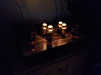
Some images are provided. One is a look at the loudspeakers, the rest are screen shots of foobar and rephase in both the front end and crossover machines to provide examples for the above text. Note that the mids/tweets are indeed aligned vertically, the woofers/sub placed in more acoustically advantageous positions for the room. Details in some images may be out of date, a reflection of how easily (and often) different things can be tried, but they serve their purpose.

The images are, in thumbnail order shown,
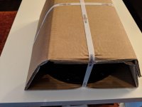
the loudspeakers
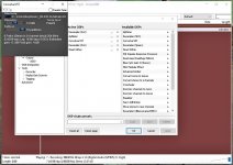
foobar dsp stack on front end
mux modular on front end
expander on front end
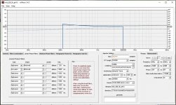
curve in convolver on front end, shown in RePhase
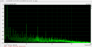
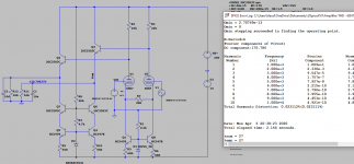
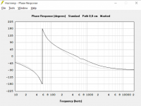
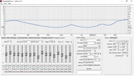
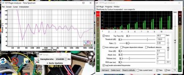
expander under test in VST Plugin Analyser, phase
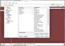
dsp stack on crossover machine
convolverVST on crossover machine
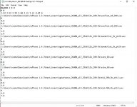
convolverVST config file on crossover machine
midrange filter on crossover machine shown in RePhase.


5. Updates

8/26/20:

Since the original post, changes have been made. One was forced on me. That occurred when a brutal power outage with multiple 'flickers' took down my front-end machine's MBR, making it impossible to boot the system without a rescue stick. Through dos on the command prompt I could see that files appeared intact, but I could do nothing to repair the MBR, nor could any rescue medium I built off the net (having multiple computers can be a help). I even tried Geek Squad, who were helpless. Eventually the exact setup (remember where you put those config files; DOS isn't the best way to search for them) was recreated on a spare and nearly identical machine, leaving me with a dead spare (the original front end) which was wiped, reformatted and reimaged to a clean UEFI/GPT setup. MBR is probably still dead. I found that the MS ISO images refuse to load onto anything with MBR partitioning. How nice. But it's back up again, waiting for something to do, and the music system is back as good as before.

In fact, it's better. I decided to 'expand' my multiband expander from 10 to 17 bands (incrementally, first 12, then 15, then 17). The 17 bands each comprise about 0.58 octaves. Phase and magnitude linearization become touchier the more bands you add; the current model has swings to +/- 4*, though the majority of the usable frequency range is less than +/- 3*. I also decided upon the oddball 256.4ks/s sample rate since that gives the best distortion figures, and it's doable with Sox resampler and RePhase filters. The result, despite worse (but still not bad) phase characteristics, couldn't be ignored --- the pluses of shorter frequency bands outweighed the minuses by a good deal. It sounds better than ever, and I know this because I still have every expander config I've made, each with its own long babbly title, and can A/B with the earlier models. It was worth every hour. How I wish my sound card hardware had arbitrary sample rates too, but Sox is so good it's pretty much a wash. The improvement is stark, in fact. Even a few vocal recordings that seemed hopelessly sibillant are smoothed considerably without resorting to notch filtering. And to minimize the amount of resampling I reran my 'room curve' on rePhase at 256.4ks/s also. It's endless hair-pulling and endless fun.

All processing is an artifice anyway. The major 'trick' to removing artificiality from expansion appears to be the narrowing of bands. At a point this collides with less manageable phase at least on reaxcomp (which is, after all, a freely-offered plugin).


9/19/20: Major change made to hardware. Remarkable results. See post New Horn in Town? for details and photo.

Attachments

  • speakers_cropped.jpg
    speakers_cropped.jpg
    98.3 KB · Views: 691
  • foobar_prefs_fe_crop.jpg
    foobar_prefs_fe_crop.jpg
    151.7 KB · Views: 521
  • foobar_mux_fe_crop.jpg
    foobar_mux_fe_crop.jpg
    144 KB · Views: 492
  • foobar_reax_fe_crop.jpg
    foobar_reax_fe_crop.jpg
    156.7 KB · Views: 502
  • rephase_fe_crop.jpg
    rephase_fe_crop.jpg
    174 KB · Views: 494
  • VPAreaxphase_crop.jpg
    VPAreaxphase_crop.jpg
    161.2 KB · Views: 146
  • foobar_pref_xo_crop.jpg
    foobar_pref_xo_crop.jpg
    102.9 KB · Views: 129
  • foobar_conv_xo_crop.jpg
    foobar_conv_xo_crop.jpg
    103.6 KB · Views: 101
  • convolverconfig_crop.jpg
    convolverconfig_crop.jpg
    95 KB · Views: 103
  • rephase_mid_filt_xo_crop.jpg
    rephase_mid_filt_xo_crop.jpg
    143.8 KB · Views: 116
  • Like
Reactions: RRPD4130

FS: B&C 12NBX100 woofer 12" new

Never been used B&C 12NBX100, new in box and packaging.
B&C Speakers

This woofer is really a beast; demodulation rings, 4 inch voice coil, 2000W continues power handling, 96dB sensitivity and 10mm xmax!!!!
Goes deeper and louder than most 15" or even 18" woofers!
Can be used as a subwoofer or in a 2- or 3-way system

Can be send to any location in Europe.

Price: 180 euro excl shipping

Attachments

  • IMG_20200103_174215.jpg
    IMG_20200103_174215.jpg
    769.4 KB · Views: 221
  • IMG_20200103_174238.jpg
    IMG_20200103_174238.jpg
    970.4 KB · Views: 226
  • IMG_20200103_174315.jpg
    IMG_20200103_174315.jpg
    964.7 KB · Views: 207

Using EL34 for allen wright's pp-2c

Hi Everyone,

I will be building Allen wright's pp-2c ordering parts at the moment. A question for fellow forumers who build the pp-2c or have experience in the design.

I have 2 pair of winged =c= el34 from previous amp, and wanted to use it till it die on me. But instead of building a pp-1c catered for el34 I would like to build a pp-2c which is for kt88 which I may use in the future. And from Allen wright's words in the forum pp-2c seem to be a better design.

Beside changing the value of cathode bias resistor to bias it according to el34 max dissipation rate. What are the other component values needs to be changed? Does the screen resistor value or 470ohm need to be change to 4.7k ohm as stated in pp-1c?

I will be using the same transformer spec as stated in pp-2c so around 450v plate. Not sure if I'm allowed to post the pp-2c schematic which I found on other forum.

Hope to hear some advice. And permission to upload the schematic for some further questions. Thank you.

-askae

Lanzar 100 (old school) repair help needed.

I have a Lanzar 100 (old school) car amplifier that dug out to try in my kids car.
It haven't been used for a looong time so i wasn't sure if it would start at all. It played for a few weeks but now it stopped working.
The power lamp comes on but no sound from it.
I checked so there is signal from the stereo both rca and remote. Eventually found that diode D6 was literally broken in 2 pieces when i started to measure the components.
I cannot read the values on it and was hoping that maybe someone could help me with this and if there maybe is something else that is not ok that made the diode fail. Attached some pictures of the amp.
Thanks in advance.

Attachments

  • image2.jpg
    image2.jpg
    243.1 KB · Views: 185
  • image9.jpg
    image9.jpg
    386.2 KB · Views: 127
  • image4.jpg
    image4.jpg
    140.3 KB · Views: 113

Brahma 12 Box size

A few months ago I scored some old Adire Brahma 12". After looking up old reviews and specs, I thought $125 for two of them in very good condition was an absolute steal. In some old threads and from the person I bought them from, box suggestions were around 2cu.ft. for sealed and 3cu.ft for ported. Wanting to get some really deep bass for HT, I am looking into ported. Threw the driver into WINISD and let the software come up with parameters for C4/SC4 box. It suggests 10.55 cu.ft. and 21hz port tuning. Looks like a nice response but seems WAY too big of a box. I threw in some smaller boxes and different tuning just to play around. The 7 cuft still looks nice, but going to 3cuft it seems to drop off quickly and the F3 isnt all that impressive. Am I missing something here? Any suggestions for a smaller box with substantial low end response? I have included the driver parameters in the screen shots. I got that information from the person I purchased them from. He said he had actually tested the drivers and confirmed Fs etc.

Aleph P remote (Pass Labs)

I had an Aleph P preamp (commercial, not diy) which I sold to a friend a couple of years ago when I was laid off. He says the remote isn't working and asked if I could fix it. I do a lot of diy, and had built a diy aleph p before I bought this one. I do have the service manual as well.
Thoughts as to which part(s) might be bad and need replacement? I haven't looked at it yet.


Sent from my iPhone using Tapatalk

Denon DVD2900 tweaks

Last week I made the first steps to modify my Denon DVD2900. I have started at the output stage. The first thing I did was carefully removing the mute transistors from the front channels. The improvement was very clear. A transistor between the signal path and ground seems to cover the smallest details on the recordings. The player now makes a few small pops when turning on the power or changing records. But it’s not very annoying really.

The second thing I did was replacing the coupling caps with polypropylenes. There capacitance is now only 6,6uF compared to the original >220uF. If the cap is too small it will affect bass levels but I have calculated that with a 10k load the –3db point is 2Hz with the new caps, so I think I can live with that. Also this time the improvement was clear. The high frequencies sound cleaner.

Next I will continue working on the output stage. Have a look at TR231 in the pic below. Depending on the state of the transistor the IC215 amplification will be roughly 1 or 2. The wire that changes the state is marked “PCM/DSD”. My guess is that the stage amplification is changed depending on weather the record being played is a CD or SACD/DVDA. As the TR231 could have a similar effect on the sound as the mute transistors I would like to remove it. My logic says that removing TR231 will make the sound level change depending on what format is being played. I can live with that if the sound is improved. Has anyone made similar mods? Any thoughts?

The DVD2900 has two pairs of front channel outputs. I will connect one pair of outputs past the coupling caps directly trough a resistor to the op-amp. This should work as long as the preamp has coupling caps on the inputs. Anyone tried this?

Also more ideas about easy improvements are appreciated!

-thomas

Attachments

  • dvd2900-output.gif
    dvd2900-output.gif
    15.6 KB · Views: 3,934

How to safely pad the output of a NAD D 7050

Hi people!

I need advice since my electronics knowledge is at beginner level. I would need a line level converter to take signal from low power class d (NAD D 7050) and feed it to high power, differential input class d (Hypex NC400), in home use. This is to save money, so the solution needs to be cheap. Almost all commercial L-pad products are made for car use, which play a little different rules. Replacing the D 7050 with something else with similar or better digital features is mostly too expensive, but any recommendations will be considered.

I've read about L-pads made of two resistors, which would be fine, but since taking signal from class d and putting it to another class d, I thought maybe I should filter the noise. The D 7050 has noise in abudance, as per ASR measurements, switching at ~850 kHz. The NC400 is a lot cleaner, switching at ~460 kHz. So do I need a cap and how to wire with the L-pad? Just parallel after it? Which values you'd recommend for all components?

D 7050 has gain of ca. 20 dB, it should be SE on speaker out. Its noise starts to climb after 25kHz. NC400 has differential input and 100kOhm input impedance if my memory serves. Not sure if that makes a difference in the end. Service manual for D 7050 can be found here. Optionally if digital out can be realized easily, that would be great.

I posted this same earlier on analog forum.

Tavish 6SL7 Phono build

So I stumbled across this phono stage a few month ago and immediately knew I needed one:

Tavish Design 6SL7 Vintage Phono

After spending some time (quite a lot actually) on compiling a BOM and after a few emails with Scott (the owner of Tavish who's been super helpful so far), the first parts are arriving.

This is my first tube project and I'll try to update regular progress - and rest assured I'll need some advice along the way. 😀

Tubes, PCB and enclosure are in the house ... waiting for a shipment from mouser.

Attachments

  • JoC6Ho0.jpg
    JoC6Ho0.jpg
    327.4 KB · Views: 1,075

FS Elekit TU8600R + AER MK1

Hi all. I am selling (because I need cash) my loveled Elekit TU8600R upgraded by Victor with LL2770 and resistors set plus my own upgrade: four VCAP TFTF and Gold Lion 300b and ECC82, ECC83 by 1100 eur. + paypal + shipping cost

AND another treasure.... pair of AERMK1 hand matched by factory for 1200 eur +paypal + shipping cost (I have been the only owner and use was very light).
(and a gift... another AERMK1 totally working as spare part).

Pics later (I am out of home in this moment).

It would desired sell both together because this combination is really amazing

This is a very sad time for me...

Thanks

Audax AM TW 74 A TW74A TW-O74 TW-074 TW074 Datasheet wanted

Who can upload a genuine datasheet of this AUDAX tweeter, (maybe there are various versions) ?
A mylar diaphragm is here in use.
Maybe the TW-51 A is a replacement, if the front shape is the only different:
http://www.audax.com/archives/AMTW51A - Catalogue 1986.pdf
NOS Audax Mylar Dome Tweeter - AMTW51A - 8 Ohm | eBay
Thank you for advices.

Attachments

  • Audax TW-74 A-IV.jpg
    Audax TW-74 A-IV.jpg
    105.6 KB · Views: 663
  • Audax TW-74 A-III.jpg
    Audax TW-74 A-III.jpg
    69.8 KB · Views: 323
  • Audax TW-74 A-II.jpg
    Audax TW-74 A-II.jpg
    60.6 KB · Views: 567
  • Audax TW-74 A-I.jpg
    Audax TW-74 A-I.jpg
    94.6 KB · Views: 523

need simple anti-thump

Hi,

i'm building a medium-sized power amp & don't need a complex relay-type of anti-thump.

Years ago I saw a simple circuit using a fet on the very input of the power amp; I recall that this device momentarily shorts the onrushing turn-on votage, then from here on it doesn't count.

Anybody seen this circuit?

I think it's also possible to extend this circuit to double as overload protection for the input.

thanks.

FS Quad ESL57 EHT boards - brand new

Hi everybody,

from a project that never happened. I still have a pair of standard EHT boards for the Quad ESL57 manufactured by Electrostatic Solutions. I seem to recall that they have never been used. They are 150,- USD new, if I'd get half of that -i.e. 75,-USD (plus shipping) - I shall be a happy camper. Payment vial paypal. Picture at request.
Thanks for looking.

Digital Vdc Panel meters with independent power source

I'm trying to find a little digital voltage panel meter like these ones from Adafruit

https://www.adafruit.com/product/705
https://www.adafruit.com/product/460

But I need one that has a completely independent power source. The 2 wire one draws current from the thing it's measuring to power itself, and this won't work for my application.
The 3 wire one draws power from another source, but there's still a common ground shared between the thing that is being measured and the meter.
For the life of me I cannot seem to find some sort of 4-wire version of this, that uses an independent +5V or +12V source connected via dedicated 2 wires, and then a separate 2 wires that connect to whatever I'm measuring voltage on.

There must be something like this available somewhere.. I'm thinking along the lines of a multimeter, it's got its own power source, and then a pair of leads that measure voltage. I need something that is dedicated to measuring voltage, and could be panel mounted though.

Has anyone seen something like this? I've been scouring Amazon, digikey, mouser, ebay.. Cannot seem to find what I'm after. Any direction on this would be appreciated.

Simple 2-way Crossover Rebuild... Help Please?

Hi Guys

I've inherited someone else's project: Nice 2-way speakers that were never actually rebuilt.

I've got everything sorted except the crossovers. I have the originals which had never failed, but they have been ruthlessly extracted. So, I'm unsure how to wire them, as I don't really understand them at all.

Nevertheless, I have built amp kits and the like and can follow instructions.

Whilst I don't want to waste money, through this rebuild, I'm hoping to apply as good components as possible. I figure I might as well while they are open.

In essence, in each speaker I've got two wires coming from the tweeter; and two wires coming from the woofer.

I'm hoping some of you kind souls might be prepared to: -
  • Take a look and tell me if the Capacitor is a really good one for the job, and worth keeping?
  • Instruct me (Pics?) which wire goes to which point on the crossover

[MUCH APPRECIATION IN ADVANCE!]

Here's some pics of one of the crossovers. I've got two of 'em, identical!
(Hopefully, you can open these pics for a closer look...)

Attachments

  • 2-way Crossover 1.JPG
    2-way Crossover 1.JPG
    857.4 KB · Views: 506
  • 2-way Crossover 2.JPG
    2-way Crossover 2.JPG
    570.1 KB · Views: 445
  • 2-way Crossover 3.JPG
    2-way Crossover 3.JPG
    890.8 KB · Views: 457

Elekit TU-8600R vs. Audio Nirvana 300B SET

Anybody out there who knows them both?
I´m looking for an affordable amp with best value/sound for money relation.
Or will diy one from scratch a more promising way?
I think I have the necessary skills. I´ve built several SS amps over the last decades.
My main speakers are Sonics Alegra 4Ohm,91dB/W/m and I´m working on an open baffle 6Ohm, 96dB/W/m.
I would be grateful for your experiences and tips.

Ideal THD vs Frequency for SET

What is the ideal THD vs Frequency plot for the SET amp?

I checked Stereophile reviews and I find some amps are very flat, but some are not, which is basically no relationship to the price, so I guess it is a designer's intention. I wonder why the goal is so different.

Flat

Lamm ML2.2 monoblock power amplifier Measurements | Stereophile.com

Non Flat

Wavac SH-833 monoblock power amplifier Measurements | Stereophile.com

Sharp CP-1122x 2 way speakers

I dug these out of storage yesterday. I had them in my bedroom during my teenage years. I hooked them up and they still work fine. Sound is actually not too bad. Bass is not that deep but ok for 8in drivers. Mids and highs a touch harsh.

I recently built my first set of speakers (Overnight Sensations - not from a kit). I was interest to look at the speakers and crossover so I took the back off.

I was surprised to find only an inductor and cap for the crossover. I also noticed that the Tweeter was branded Sharp but the woofer is Arista brand. Am guessing it is not the original. There is a vent hole on the front bafflle but no port tube.

I cannot find any info online for the model of woofer. My immediate thought was why such a basic crossover. Is it because they were just low end speakers, or because the specs of the original tweeter and woofer might have been designed in such a way that this was all that is required? Makes the crossover in the OS speakers look very elaborate.

My next thought was that if the woofer has been replaced, has there been any consideration given to the choice of replacement at all.

The speakers look in very good condition and enclosure is in reasonable condition. I know they are nothing flash but in diy spirit and also largely as a learning experience I am wondering if I can improve them, otherwise I will just use as is.

What would be best approach here - try to find specs of the speaker and improve the crossover? Replace the woofer and also crossover?

I was hoping to find some reference to sensitivity as would ideally like some speakers that are more sensitive that the OS as I'm planning a Class A build most likely jlh 69. They seem too old and uncommon and perhaps too cheap to have detailed info still available. Made in Japan though! Cap is Nichicon. Inductor looks like ?iron core.

Attachments

  • 20200801_142608.jpg
    20200801_142608.jpg
    889.3 KB · Views: 180
  • 20200802_092419.jpg
    20200802_092419.jpg
    948.4 KB · Views: 143
  • 20200801_142617.jpg
    20200801_142617.jpg
    941.7 KB · Views: 174

Linkwitz LX active speakers + MiniDSP 2x4HD

Due to unsuspected change in our lives, I offer my LXmini speakers with a 2 channel amplifier build in the base. i just finnished them.

In the base are 500VA toroids, analog supply with 72mF capacitance and 2 amplifier modules 120W each (2x A1186 / C2837 Sanken per channel)

Make me a fair offer!

The speakers are white / Birch Ply

PM me for more pictures pls

Attachments

  • IMG_1167[1].jpg
    IMG_1167[1].jpg
    474.9 KB · Views: 334
  • IMG_1166[1].jpg
    IMG_1166[1].jpg
    508.1 KB · Views: 342
  • IMG_1169[1].jpg
    IMG_1169[1].jpg
    747.1 KB · Views: 346

Symasym 150W at ebay...

150w Class AB Audio Power Amplifier Board PCB based on symasym 5-3 | eBay

Has anyone ever bought this and made it?
I would like to buy this board and make it using DC ±55v 500va transformer and njw1302,njw3281 2pair.
Of course, since it is sold as a commercial product, it will work, but it is questionable what quality it will show.
The only difference from the original is 22 ohms and 2.2 ohms. I'm worried if the change is too small.

Attachments

  • s-l1600.jpg
    s-l1600.jpg
    90.8 KB · Views: 652

Home theater enclosure help, noob here.

Hi all, I am new to DIY Audio. It started with a living room renovation and not being able to find off the shelf speakers\woofers at the right size to properly integrate into my design.

I am trying to design two enclosures that will each house a 10” subwoofer. The subwoofer’s I have picked up are Dayton Audio RSS265HO-44 10".

The two enclosures I have built so far can be seen here:
d6lWsbim.jpg


The right enclosure is the first attempt, it uses the starter enclosure package for a 10” sub from parts express. I did not have a router at the time so I thought this would save time. I used subbox.pro to get rough calculations. The port width is roughly 1.5” and length 13.5”. The outside dimensions are 25.5” x 13.75” x 13”.

Internal picture:
hJ95NA8m.jpg


The left enclosure is the second attempt, using a double MDF wall on the front, and more precise box calculations from speakerboxlight.com. The port width is 1” and length is 33.25”. The outside dimensions are 26.5” x 16” x 11”. This site allowed me to select the exact model of my subwoofer and create an enclosure around the specifications.

Internal picture:
CxwkML4m.jpg


*note, when they were glued\screwed the port lines up with the front wall.

I have noticed the older enclosure is a lot louder and deeper, whereas the newer enclosures sound more muffled with less high and low end. However, the excursion of the subwoofers both appear to look the same. I *thought* I would get a much better sound from the second design as the calculations were followed more closely from the site.

I am getting in over my head here, and wondering if there is anything I can do with the second design to get similar resulting highs\lows I get from the first design. The height of the box is more ideal for my renovation. The only panel that isn’t glued on the second design so far is the top, but I should be able to make some slight changes with the port width\length if that could help.

This is for home theater, looking to fill in the lows and be decent with mid-range bass as well, mainly for movies.

I have tried polyfill, changing channels on the amp in case it had something to do with the l/r. But the first design continues to win.

Any advice would be appreciated. If I am missing any details let me know I will try my best to provide them!

Will Eminence Lab12c crossover nicely to Beyma 8cx300fe?

Furthering my research towards a high SPL, full range studio monitor... Will the Eminence Lab12c crossover nicely to a Beyma 8Cx300Fe at around 200 Hz?

WinISD seems to think so, from where I'm looking... I haven't decided if the Lab12c will be sealed or vented, cabinet size, Eq. etc... I'm just looking to find out if the crossover between these two drivers will be problematic... whether the sub will play well up to 200 Hz and the coaxial will play well down to 200 Hz (24 dB LR, possibly)?

At this time I'm looking at the Hypex FA253 to handle crossover and DSP duties..

sUp3CWZpoV1QFqg-a-Gx3GlIT9dOt47zNWxaJiPiM9iNrhEuIEYDSbHhH1XkHbK6FJ5Cp6a6LIJmFj-S9Sz8_rIZki4Nd7sBUIDUeky761cIVxNSBpDaylf9pCnudaYoEb4l7tcxrw=w2400


.

Visaton drivers, any good

Hi And thanks for reading.


Trying to find any opinions on the visaton bg20 driver if you have used it or heard anything about it at all.

I am using it in a 3-way open baffle speaker, have cut out the dust cap, fitted a phase plug, applied some damping to the magnet and chassis and it sounds good, much better than the £25 price tag would suggest.

Would it be possible to purchase a driver for about £100 which would be a considerable improvement over the bg20, or should i stick with the bg20 if there is little improvement available at that price tag.

I am using a fane bass driver up to 120hz, then i want a mid to cover me from 120hz to 6khz, after that i have a b&c tweeter to reproduce the highs.

The mid i am needing to use as open baffle, power handling of 50 watts rms, not a full range driver please.

Thanks.

Hifonics Thor XI missing parts

Hi guys !

Long story in short. Amp came in for a repair.
Hifonics Thor XI missing some parts:

resistor - RB12 + RA12 (both channel missing, both badly burnt PCD and traces)
cap - CP15
cap - CP17

Picture two (in the middle) is a picture I found in the web of the same amp, but it's so low in resolution i can't read the parts.

Voltage across terminals of CP15/17 is ~ 12v. So a cap V rated 16v or 25v would be sufficient, but what uf ?

RB12 + RA12 - don't know what they should be, but looks like 1W resistor ?😕

Attachments

  • 0.jpg
    0.jpg
    457.8 KB · Views: 164
  • 1.jpg
    1.jpg
    86 KB · Views: 148
  • 2.jpg
    2.jpg
    599.4 KB · Views: 159

My Linear Tracker (a new variation perhaps?)

hello everyone,

I´ve been using this arm for a year now and I´m very happy with it, the main design goal was simplicity and overall low mass horizontal and vertical, I wanted to eliminate the use of air bearing with the corresponding air pump, after a lot of tinkering with different carriage designs like magnetic, hydraulic... ball bearing is in my opinion the more elegant approach for a linear tracker and I finally got to a design that gave me what I was looking for.

the arm is clearly based on the concepts used in the engineering masterpiece the "Opus Cantus" and the "Souther" at first I was going for a copy of those designs but I thought it could be made more simple and this is the result:

b3PqeJp.jpg


as can be seen the whole carriage and arm becomes a type of "linear ball bearing" this is an illustration of the basic concept ( "thrust ball bearing")

mAyD6TW.jpg


all the rods are from a normal telescopic tv antenna:

riGcGnF.jpg


surprisingly this rods work very well, they are smooth, easy to work and they are everywhere!!! I did try glass rods and it also worked but I could not find them with an adequate diameter so the carriage was bulky and I ended up using the antenna rod.

as can be seen the ball is placed in the middle channel formed by the two circular rods put side by side, the contact points are four per each ball :

6L1daoV.jpg


side view with the contact points:

Ku21Sep.jpg


as you could imagine while traveling the disc from start to finish the two balls change position in relation to the upper carriage this might seem like a mayor problem limiting the arm range but in practice is not even a concern :

2M94YW3.jpg


q4zzWS9.jpg


(please don´t mind the cables, I was doing some tests for mono connection)
the movement of the arm is very smooth and free from malicious drag, it goes very well with high compliance carts.

Building LM3886 Amplifiers

Hello world, i decided to share my experience in building my first amplifiers, my goal was to Bi-Amp a pair of speakers SVS ultra towers that requires a quite amount of power, i decided to build 2 amplifiers with 2 modules of 3 x LM3886 chip each, I chosen chipsets LM3886 because they have a good reputation regarding sound quality, and the modules are capable of delivering generous 150 Watts per channel @ 8 ohms.
Some photos attached, please fell free to criticize and comment.

OneDrive

12BZ7

Hi everyone!
I have a bunch of 12BZ7 tubes, and want to to make good use of them. The general opinion I heard was "every section is like two // 12AX7 triodes"
I wonder if someone actually used it, and found some sweet spot, I mean like the "200V on the plate at 3 or 4 mA" preferred by 12AT7s.. Of course I can experiment and found by myself, and I' ll do, but I found interesting to hear about some others experiences
Cheers
J

VC bottoming out? Air leak? Need some help!

Now I need some serious help, I feel like I have tried everything and I cant figure out the problem.

The story:

I have a 12v portable PA system. I use a 200ah lifepo4 batterybank, a pioneer mono gmd9601(500w@4ohm) with 2 tham15 (15ps100) for subs and a gmd8604(300w@4ohm x2 bridge) for tops. I blew two drivers last summer bcs someone turned on the bass boost (50hz). They never recovered from that. I played around with amplifier gain on the mono amp afterwards, and toasted them. Kind of an experiment as much as an accident.

I bought two recone kits and a new driver and built a new box. The first reconed sub sounds nice in the new cab, but the second (2) reconed sounds like its bottoming out. Not like a rub, more like a solid clank when I turn the volume a little bit up. I took it out of the cab, the clank is getting more pronounced, sound like a metallic rattle. I think for my self, maybe it could be the dust cap is off centre. So Im cutting of the dust cap, recentering it, rattle is still on board.

Here comes the weird part. I open the new 15ps100 . It says on driver it is tested before shipping. Mount it inside tham 15, and rattling/clank is here as well. I take it out of the box and try it open air, it rattles even more like a snake. I try my other amplifier, same sound. I put the brand new 15ps100 in the other cab, same sound. I go back to my first reconed sub, testing both amplifiers, and works like a charm.

Made a filter setting on minidsp, cut off at 38 and 110 hz. No improvement. Now I'm frustrated and getting creative. I go back to the driver with recentered dustcap, and try to find out if it is a misaligned voicecoil after reconing. I put on a clamp, and add force on frame until I hear rubbing sound, and release, and rubbing sound goes away. Try this again for 3 new angles, and I conclude it is not a rub, more like a bottoming out sound.

Now I'm out of ideas. The driver is rated for 700w rms and amp 500w, and the sound was there right at the beginning. I cannot remember this sound from before I blew them, but who knows. Maybe I wasn't so critical as I am now. But there is definetely something fishy going on.

Do drivers bottom out in free air always? Is this normal when pushed maybe 100 or 200 watts on music program? I have inspected amps with multimeter, no DC from amp terminal. Resistance on speaker terminals is perfect, so not blown driver.

I have an event coming up in a couple of days, and I did not expect so much hassle. I am getting quite anxious to say the least. Very new to diy pa, and feel like I have put on too big of a challenge. Now I am asking for help.

Regards

Kristoffer

(posted on another forum aswell)

MTX thunder 2160 repair

Hi, I have a MTX thunder 2160 that won’t power up. It had burnt power supply fets which I replaced and it had 2 burnt resistors that I couldn’t read the value and the position was burnt off the board but they connect from the small coil To the power supply fets. I replaced them with 1k resistors because the other side of the coil had a 1k but after some research I believe they are supposed to be 61.9 ohm. After replacing a couple other resistors that were bad and a bad cap and power supply mosfets the amp still won’t turn on. I pulled the rectifiers to make sure I don’t damage the output side before putting power to it and there is no power getting to the rails. I also pulled the output fets out too because I have new ones to put in. I believe the IC’s are in protect mode or bad. There is no power coming out of the 494 IC to the power fets. I have 12v at the center leg of the power fets but 0v on the outer legs. If anyone could help with verifying the resistor values of the ones by the small coil and verify if my voltages on my IC’s are ok that would be great. I really appreciate any help, thanks.

TL494
1: 0.01v
2: 4.63v
3: 0.06v
4: 0v
5: 1.57v
6: 3.42v
7: 0v
8: 12.01v
9: 0v
10: 0v
11: 12.01v
12: 12.01v
13: 4.94v
14: 4.94v
15: 4.49v
16: 0v

LMT339

1: 4.73v
2: 0v
3: 12.01v
4: 4.67v
5: 3.38v
6: 1.08v
7: 3.38v
8: 3.93v
9: 4.94v
10: 4.94v
11: 7.17v
12: 0v
13: 4.73v
14: 4.73v

Attachments

  • DB33EB4F-E355-424C-918B-C3029D3E39B4.jpg
    DB33EB4F-E355-424C-918B-C3029D3E39B4.jpg
    955.3 KB · Views: 241
  • 974F8F1C-7E75-4CBD-90E7-DE6A1F0227A1.jpg
    974F8F1C-7E75-4CBD-90E7-DE6A1F0227A1.jpg
    1 MB · Views: 216
  • E61FD4E2-7FEE-464E-8DFC-F77F76AAA8E4.jpg
    E61FD4E2-7FEE-464E-8DFC-F77F76AAA8E4.jpg
    981.7 KB · Views: 248
  • DF74B798-4D91-4BAC-B296-93BCE1273293.jpg
    DF74B798-4D91-4BAC-B296-93BCE1273293.jpg
    1 MB · Views: 231
  • 408B576C-3675-4865-B15C-3721AAA89CC2.jpg
    408B576C-3675-4865-B15C-3721AAA89CC2.jpg
    950.9 KB · Views: 183

Noob needs advice on amp module and PS

Hey ho fellow inmates!
I'm a speaker builder looking to assemble (I won't dignify it with the word build) my first amplifier.

I have a nice Dynaco style case and I've experimented by implementing a prototype using a Sure chip amp and old computer PS I had lying around:
amp.jpg


For final production I'd like to upgrade the PS and amp module with the following in mind:
- the app will be left on 24/7 so I'm looking for class D efficiency (important)
- I'll need around 100 w/ch to drive my speakers
- the components need to comfortably fit in the case
- the final product should deliver a very high quality signal (audiophile, but not "snake oil" audiophile)

The amp module choices seem limited to unknown Chinese modules and pricier Danish and Euro units. (I'm leaning towards the latter) but with my limited knowledge in this area I'm finding it difficult to zero in on an outstanding and newb-proof PS/Amp combo.

For example - I was looking at this post and it seemed pretty straightforward. Archimago's Musings: An Inexpensive Hi-Fi Class-D Stereo Amp for the 2020's: Hypex nCore NC252MP (DIY Assembly)

Are there any other alternatives I should be looking at?

Thanks!

Allo Shanti Dual 5v Linear Power Supply (Regulated, Ultracaps)

A long time Allo fan, I bought two of these supplies thinking one will go to my DIY projects. DIY hasn't gotten touched in a while, so trying to find a new home for the second unit. Additional USB C and uUSB adapters included as I have plenty from other Allo supplies. Listing as Used even though it is practically new.


SOLD. Thanks!

Attachments

  • IMG_2378.jpg
    IMG_2378.jpg
    701.9 KB · Views: 233
  • IMG_2377.jpg
    IMG_2377.jpg
    797.9 KB · Views: 229
  • IMG_2379.jpg
    IMG_2379.jpg
    752 KB · Views: 224
  • P1330046.jpg
    P1330046.jpg
    722.3 KB · Views: 220

Monaural Streams

If you like listening in monaural, I was tuning across the AM band recently (3rd attempt at audio based mole eradication project) landing on KBRD AM 680. "This sounds annoying enough". After day, "They're playing some pretty fun stuff!". Anyway, thought I'd share here - KBRD Radio AM 680 - America's musical museum playing music of the 1st half of the 20th century

"Whether you like piano rolls, pre-1920 cylinders, 78s from the 20s, 30s, 40s and 50s or early 45s and mono LPs, this is your station. Broadcasting on AM 680 with the full audio spectrum. On the internet we stream in the original monaural not wasting bandwidth. Better than CD quality."

I'd like to stream them through my rPi player. Digging out their stream URL I get something like http://205.134.192.90:680. Works when I plug it into the LMS "Tune In" URL.

Enjoy - and please add your URL for other Monaural Streams you know!

841/KT88 Unity-Coupled Amp Update

I updated my Unity-Coupled amp and wrote up a detailed account here.

I've attached a simplified schematic and some distortion test results.

Summary Below:
100mW: 0.030%
500mW: 0.040%
1W: 0.044%
2W: 0.084%
5W: 0.12%
10W: 0.16%

Attachments

  • IMG_20200715_124223144.jpg
    IMG_20200715_124223144.jpg
    1 MB · Views: 318
  • UC_841.jpg
    UC_841.jpg
    120.5 KB · Views: 299
  • IMG_20200729_195748833.jpg
    IMG_20200729_195748833.jpg
    322.1 KB · Views: 293
  • IMG_20200729_195823226.jpg
    IMG_20200729_195823226.jpg
    577.8 KB · Views: 263
  • R100m.png
    R100m.png
    105.9 KB · Views: 288
  • R500m.png
    R500m.png
    106.5 KB · Views: 100
  • R1W.png
    R1W.png
    108.9 KB · Views: 89
  • R2W.png
    R2W.png
    108.5 KB · Views: 70
  • R5W.png
    R5W.png
    109 KB · Views: 70
  • R10W.png
    R10W.png
    107.1 KB · Views: 77

Not your dads tube preamp...

Hi,

I'm thinking about a tube preamp. It has to be balanced, use the least amount of tubes and use solid state to support the tubes. I opted for 6SN7 in differential pair loaded with CCS. Second stage is a buffer with an emitter follower, loaded with CCS too.
Split CCS for diff pair should help hold both tubes in reins when they mature. Outpu buffer is good with 10k//10nF at around 3Vrms. Any feedback is appreciated!

Attachments

  • 92497215_499882134012719_3549727883880562688_n.png
    92497215_499882134012719_3549727883880562688_n.png
    52 KB · Views: 516

Melos SHA GOLD Line Stage

I have always loved my Melos SHA GOLD Linestage, but it was such a design nightmare! The servo tied to heater, photoresistor volume control, wonky balance control, remote from hell, three mute circuits, crazy wiring, etc.

Also never was a Headphone guy, even tho this unit apparently was one of the best headphone amps on the planet 30 years ago...

But as a single ended input - balanced out linestage, well, it was just awesome sounding - the 6922 tube, lowish Zout, and true balanced out...

So I finally managed to trace out the linestage - with voltages...comments before I build??

Attachments

  • scan.jpg
    scan.jpg
    241.8 KB · Views: 696

Vintage Califone Motor Noise

I have a very old Califone, probably from the 60s, which is made from metal parts and has a heavier metal arm. I say all this since invariably when I say Califone I get, "it's junk, get a better blah blah blah..." I know what it is and understand its limitations.

Years ago I ripped the internal amp and tonearm wiring out and ran two silver leads out of the tonearm, connected to a Stanton 500 cartridge with the coils wired in series. This setup works really well for 78s, transcriptions, old mono LPs, etc.

But the table has a lot of motor hum that transmits through the tonearm when playing. I want to be clear, this isn't cartridge hum, which is not a problem, but a transferred constant hmmmmmmmmm that is only there when the needle is in the groove. It's definitely mechanical.

The idler is soft and pliable, as are the motor mounts, so I'm a bit stuck as to where to look to try to reduce or eliminate the noise. It has a very small idler - about 1.5" round - so I wonder if it's just going to be noisy whatever I do due to the size. I have not been able to open the motor to lubricate it, so am wondering if that is the likely culprit.

Any thoughts are appreciated.

BGW 750A - output transistors

Hi all:

I am working on restoring a 45 year old BGW 750A amplifier which had been retired from service at Universal Studios, having proudly been part of the "Sensurround" revolution.

The amplifier was stated to "work but occasionally go into protection", which I assumed was due to inadequate heat dissipation as both the thermal switches for the (really loud) fan had been disconnected and the thermal grease on the output transistors had become thick & cruddy with age. I am replacing the mica insulation and the thermal grease on each of the output transistors and installing a new quiet DC brush-less fan.

Each channel has 10 NPN 2N3773 devices. Using my cheap transistor checker, I got the following hFE/Uf readings:

Channel A

1. 55/470 6. 55/489
2. 44/490 7. 51/494
3. 73/499 8. 59/485
4. 63/490 9. 82/490
5. 55/488 10. 48/498

Channel B

1. 59/490 6. 44/485
2. 24/494 7. 25/494
3. 112/494 8. 34/493
4. 22/489 9. 55/499
5. 99/494 10. 62/489

Questions:

[a] Could the variation in hFE be the cause of the amplifier heating up and going into protection?
I presume the 2N3773 transistors were matched at the factory, is it normal for these output transistors to drift with age, akin to the small signal input differential pairs?
[c] And finally, should I replace these with modern (closer matched) Onsemi devices?

Hope everyone is staying healthy & safe.

Rgds
Mayank
Projects by fanatics, for fanatics
Get answers and advice for everyone wanting to learn the art of audio.
Join the Community
507,797
Members
7,888,834
Messages

Filter

Forum Statistics

Threads
406,261
Messages
7,888,834
Members
507,797
Latest member
Moza