(Updated 8/26; see end of post)
This is a description of a DIY stereo system which comprises the unlikely combination of fairly powerful desktop computers, common surround-soundcards, modest chip amplifiers and large, efficient loudspeakers. I'm posting to explain how, using very affordable techniques, I built what I consider a theater-quality stereo system. It's lounging here because no other forum appears general enough.
This DIY hi-fi project, now about six years old, evolved from a simple attempt at providing FM background music for my fairly large cave into a main focus of my attention. It grew from analog basics into an analog/digital hybrid, then to several phases that were MiniDSP-based, and finally into a fully desktop-driven (minus power amps and speakers) system with large loudspeakers and very high output quality.
As such it has met several revised objectives besides presentation of music as realistically as possible. That part of course remains subjective, but a number of quantifiable goals help me get closer. They are
a. good definition and low distortion at all output levels
b. no clipping anywhere along the signal chain
c. lifelike dynamics
d. elimination of phase shift from source entry to drivers
e. a wide open software-driven platform (making the rest possible).
This is its current format. The entire thing could be assembled for around $2500 plus the requisite effort, as is.
1. Components
a. Speakers
Loudspeakers are chosen for clarity, range, efficiency and dynamic capacity, along with durability, compatibility and affordability. Room decor is not a factor, though with rearrangement and some faux cabinetry the exact setup desribed (minus the sub perhaps) could be made so. Their cost was ~$1800, dominating the cost of the system.
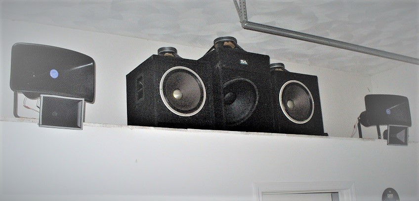
Subwoofer (1): A Peavey 18" Pro Rider is mounted in a Seismic Audio 18" downfiring sub cabinet with internal crossover bypassed. The result is a tight, smooth and efficient subwoofer that functions nominally from 60Hz on down. Its basic purpose is to relieve the bass drivers of the longest-throw frequencies, as their xmax is limited.
Woofer (2): Each woofer consists of a vintage Altec 421A mounted in a Seismic Audio 15" cabinet, again with internal crossovers bypassed. Each runs from 60Hz to 200Hz. The sound is pure Altec, tight and smooth. They are of course efficient. They cost ~$100 each used, were not recones, and worked perfectly.
Midrange (2): Each mid is an Atlas CJ-46 reflex horn loading an Atlas PD5VH driver, used over a remarkable 200Hz to 3kHz thanks mostly to the very long path length of the horn. The driver, rebranded, has been used as the mid driver of the Klipschorn. Despite its 'stadium' appearance, the horn/driver combo is clear and smooth and enables a choice of amazingly low high-pass points, which is what drew me to it. I frankly didn't expect it to work this well in a hi-fi application.
Tweeter (2): A Klipsch tractrix-hybrid horn, used recently in 'home theatre' speakers until replaced by a newer version and sold off at ~$35 each, has had its Klipsch driver replaced by an Eminence N151M-8 ring-radiator. An 0.47mF film capacitor is shunted across it to suppress residual RF from the class T amplifier, mostly to make scope readings clearer. Its minor effect on phase is compensated elsewhere in this writeup.
b. Power Amplification
As the system is actively crossed over, each speaker is wired directly to its own amplifier. Two 1-unit 19-inch surplus rack mount boxes each house two Sure AA-AB32971 stereo boards and a switching power supply, each input run through a noninductive potentiometer for attenuation. The boards house either the Tripath ta2020 (clone?) or likelier the TI TPA3118. For various reasons it is hard to tell which is used (Newark specs the 2020 for their lot, PartsExpress the 3118 for theirs). I believe all mine are TPA3118, set at 770kHz switching frequency. They have low distortion and enough power to drive the speakers mentioned (including the sub) to very high levels in a large listening space without clipping. The four stereo boards cost ~$30 each, the two power supplies about the same.
c. Crossover
The crossover is housed in a refurbished HP 6300 ProDesk with Intel I5 quad-core (running Win10 up-to-date) and a simple Vantec PCIe 7.1 sound card (CMedia 8828 chip set), used for both optical input and multichannel analog output. Driver is provided by MS. Foobar2000 is the vehicle for the crossover. The computer cost ~$160 preloaded with Win10 Pro (updated once connected), the sound card ~$50. All apps and plugins used on the crossover end are freeware or donorware.
d. Front End
The front end, another HP desktop (as it happens, a refurbished Compaq Pro with 4-core AMD A8 5500B, also running Foobar on Win10) is used to stream external sources and play recorded sources off a fast M.2-type SSD. The machine lacks M.2 boot capability but the disk is mounted in a PCIe adapter for music storage. Another CM8828-based 7.1 PCIe sound card (Sedna) is used, despite only stereo output needed; this card is one of the few options these days for PCIe-based coax SPDIF output, which my data link requires. Hardware cost is roughly same as on crossover side, with one of the plugins (Mux Modular 7.4.4, an excellent graphic patch panel meant for DAWs) adding ~$70.
e. Data Link
SPDIF is used to connect the two machines since a 1-wire solution is required for an optical connection to the crossover. This one is fairly unique though, and deserves mention. Were the machines close enough a simple cable (or even maybe a single computer) could have been used, but they are 40' apart, and the crossover and its DAC outputs must be near the power amps, which are near the speakers. Thus, a simple 74HC04 hex inverter based coax-to-optical converter was modified to drive a laser module instead of a Toslink output module and the very good 74HC04 changed to an even faster 74AC04. It is fed by coax SPDIF from the front end sound card. The modulated laser illuminates the open end of an optical cable connected to the input of the crossover machine's sound card. Tested to 192ks/s, used currently at 88.2ks/s, the final product contains about $40 worth of components.
2. System Setup
This is where the choice of fairly powerful desktops as a platform for the signal chain becomes apparent.
a. Front End
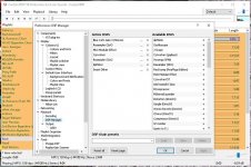
The purpose of the front end computer is to supply source material, process it and send it to the outside world as an SPDIF stereo signal. Foobar2000 is the vehicle of choice. Source material is kept on an M.2 PCIe-adapted NVRAM storage disk (except for that which is directly streamed from the web). This includes downloads, CDs etc., all of which are converted to FLAC for storage. The DSP stack has, in order,
i. Blue Cat's stereo gain module (to drop source levels ~8dB),
ii. Sox resampler to upsample for signal processing,
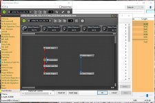
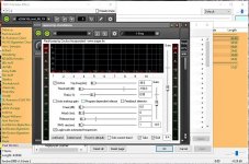
iii. Mux Modular, used solely as a wrapper for Reaxcomp which exhibits some instability in foobar otherwise. Reaxcomp, a compressor, is instead configured as a 10-band expander to restore dynamics, bands set from 40hz on up in octaves. The ideal would be of course one band per frequency, which is impossible for a number of reasons, but division into octave bands minimizes the dependence of a high frequency's expansion on a much lower frequency's level (since the former rides on the latter).
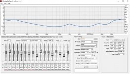
iv. Foo_convolve, the native Foobar convolution engine, which applies equalization from a curve built in RePhase (note foo_convolve seems to prefer stereo impulse files),
v. Sox resampler to match output to the data link sample rate, and
vi. Smart Dither set for 1 bit, 24 bits depth.
The output stage uses DS or WASAPI with copious buffering (latency is not a concern). A number of other (advanced) parameters are set to what seem optimal values (buffering, priorities etc. etc.). The resulting SPDIF signal exits the machine on the Sedna card's stereo coax output.
b. Crossover
Here, the CM8828 sound card is used on both ends, acting as default input on its optical-in and as default multichannel output on the 7.1 (analog) outs. Output is configured for 7.1 surround, perfect for a 4-way crossover with a single sub, all output channels set for full range.
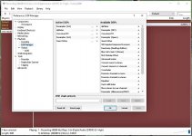
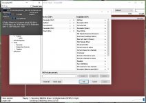
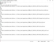
The DSP stack of Foobar2000 is loaded with Sox resampler (to upsample for filter processing), ConvolverVST (to provide 8 filters), another Sox resampler (to downsample for the output driver) and Smart Dither. "Foo_record" plugin permits Foobar to play the default sound input (in this case the optical input of the Vantec). ConvolverVST needs more clarification. Besides housing 8 separate mono brickwall filters, its configuration text file also provides
i. 2-to-8 channel multiplexing and mapping for the outputs to the sound card,
ii. precise delay for each channel, critical in eliminating propagation delay from the loudspeaker array, and
iii. a variety of other things I don't use but you might like.
It is set on my machine to 16 partitions and 'patient' tuning (beware... you may have to set tuning one level higher during initial configuration to end up with 'patient'... it is a bit high-strung but worth the effort). Depending on filter size and tuning level prepare for a long initial optimization delay but a good deal less on each startup after the 'wisdom' file has been written to desktop (which it is every time foobar is closed smoothly). The author of the plugin recommends 'measure' tuning (one level lower than 'patient') and you may like the sound and appreciate the much faster optimization time.
iv. Amps
One could always leave the amp boards sitting around naked, but I like them mounted in a box. As mentioned, I use two 19" one-unit-height surplus rack boxes. Each fits two boards and one switching PS. Of course connectors, input attenuator pots, drilling, wiring and assembly are required. I suggest the use of cheap solid copper 'doorbell wire' for internal connections, which is overkill for conductivity and holds the shape you bend it to forever.
One last item: though the amp boards are fan-equipped, you may find the on/off cycling of the fans annoying. I suppress that by placing a 5" AC box fan atop each box over the cooling vents and controlling its speed with a small variac. It works even without air conditioning in hot weather. I also install the rack box tops with spacers to leave room for air entry/exit (and for the boards, which require more height than the typical 1 7/8" available on such rack boxes).
v. Drivers
Bear in mind when positioning drivers (esp. mids/tweeters) that unless you are bolted to a chair when you listen, parallax can affect phase relations on even perfectly aligned (on-axis) drivers. With a crossover point of e.g. 200hz and its ~5' wavelength this is a fairly minor issue. At higher frequencies, say 3khz, it becomes more important since the half-wavelength is ~2" and any repositioning of your ears that creates this small propagation deviation via parallax will result in cancellation. Note also that it's nice to have frequencies higher than the crossover point on the tweeter still in natural alignment with a fundamental tone on the mid. These realizations spawned a lot of 2-way and 3-way coaxial drivers decades ago, eliminating most parallax but still, in that day, with no way to compensate the offset voice coils of the close but still axially-staggered drivers.
Obviously the most practical alignment for separate drivers would be vertical and closely spaced, certainly for a mid/tweeter pair (unless your ears' elevation changes radically). Woofer/mid? Unless you are crossing over at >1khz, probably not an issue in most rooms. Woofer/sub? No issue (in this case 60hz and its ~20' wavelength make it a moot point).
You can correct for propagation delay and frequency-dependent phase shift in a variety of ways in software, but remember that this is true only for one listening point. Good driver alignment will help spread that hot spot pleasantly over a wider area, a good thing unless you don't mind lack of mobility.
3. System Testing and Tuning
a. Front End
Clipping avoidance is important anywhere on the signal chain. To this end, recordings are conveted to FLAC (to save space over WAV files while maintaining lossless conversion, and in the case of lossy downloads, to avoid further signal loss) using Alternative Replay Gain set to 'prevent clipping according to peak'. Sox upsamples to 384ks/s during this procedure, using an option in Replay Gain. Despite extant information indicating that Replay Gain must be set during playback for decoding, my testing indicates that the track is indeed moved below clipping levels with no decoding required at playback (indeed, the option to 'Remove ReplayGain Information From Files' is greyed out for files recorded in this fashion). All this is good for me since I haven't heard a limiter I like. I don't know whether this behavior is an artifact of using Alternate Replay Gain (which I do) or not.
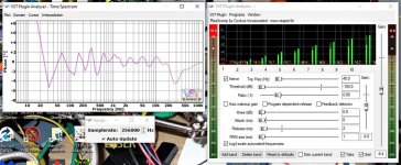
The 'declipped' source material is dropped by 8 dB or so using Blue Cat's stereo gain (which tests phase linear on VST Plugin Analyser) since the next step involves dynamic expansion. Reaxcomp is my choice, carried within Mux Modular (itself a VST which tests phase linear) for stability. It is configured for 10 octave bands of expansion as mentioned earlier, the rest configured minimally with 1ms RMS size and 2ms release, attack and knee left at 0. Threshold is maxed at -150dB and ratio set at 0.88:1 (expansive). It is tuned on VST Plugin Analyser. Bands begin at 40hz. Phase is measured and minimized via manipulation of the per-band gain controls. It takes a while, but phase is constrained to +/- 1* over about 50% of the usable audio spectrum and +/- 2* over nearly the whole thing. 3* is never reached except at very low frequencies. For some reason distortion measurements come out best at sample rates of 128 or 256 ks/s (literally, not the powers of 2) at below -120dB THD/noise. I don't know if that's an artifact of the VST or of the test vehicle, but I currently use 352.8 ks/s as my processing rate. Reaxcomp has metering for checking input/output levels. Not knowing its format (RMS?), I try to leave about 6db of headroom on output for loud tracks.
A note about meters: RMS metering, while of interest to speaker and amplifier manufacturers, is worthless for this exercise. You need a fast peak meter. Acceptable RMS levels will do you no good when your cymbals, superimposed on a huge bass wave, are being sheared off.
Next comes foo_convolve, which carries the equalization curve. It requires no phase testing (VST Plugin Analyser can't test it anyway) as the impulse it processes is generated in RePhase as a phase linear FIR with 352.8 ks/s sample rate. RePhase offers a wealth of options for windowing, tap number etc. etc. Find what you like best. I use 256k taps (as the power of 2) with 2x the number of ffts (automatic in RePhase).
Note: the Sox plugin contains a filter but it is also a FIR which can be set to produce linear phase, and is perhaps bypassed by going to 99%(?). It will also suppress aliasing and imaging if so desired (certainly a good idea on the possibly base-changing initial conversion of source material).
Sox resamples back to 88.2ks/s for output to the sound card. Foo_dsp_dither (Smart Dither) is used as mentioned; it is optional but I recommend trying it (why not, it's free). And so we exit the front end without clipping, having done due diligence with various available peak meters. It is worth mentioning that foobar has a native peak meter under visualizations, operating at the output but not pluggable into the DSP stack. We also exit with darn near phase linear processing, the worst offender being the expander as mentioned.
b. Data Link
The data link, mentioned earlier, is fairly simple but details are beyond the scope of this document. Outdated descriptions are posted on the site and elsewhere. I'll update or rewrite it someday (I assume most would use either a cable or a single computer anyway).
c. Crossover
It is the job of the crossover machine to
* multiplex stereo input into 8-channel (i.e. 4 stereo channel) output
* map these channels properly onto the sound card
* host the filters that define the crossover
* correct significant amplitude and phase deviations endemic to the loudspeakers
* impart delay to each output channel to compensate propagation delay.
All of this is done by ConvolverVST via its config text file. Since there is only one subwoofer its two channels are summed to one for 7 actual outputs (also in ConvolverVST). Clipping avoidance and linear phase are of course as important here as on the front end.
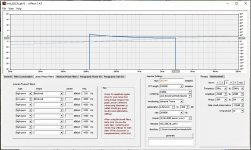
The filters themselves are generated in RePhase as phase linear FIRs with the same number of taps and ffts as on the front end's loudness curve. Crossover points are 60hz, 200hz and 3khz. The filters are brickwalls. If a driver requires some equalization it is done with an overlay of the curve onto the filter. Moreover, since RePhase permits phase equalization, phase slopes are included in the mid and tweeter filters to compensate for measured deviations from linear.
Sox is again used to resample to filter rate (here 264600ks/s, or 6x44100), then again to output driver rate (88.2ks/s). Peak meters are used as in the front end against signal chain clipping.
As for measurement and testing, the following items require some work:
* cancellation of propagation delay
* compensation for amp/loudspeaker phase shift.
i. Propagation Delay
Audacity is used on the front end machine to manufacture a pure tone burst of the proper frequency, typically but not always a crossover frequency. It is fairly easy. Simply generate a tone with duration for perhaps 20 cycles. Use 'select at zero crossings' to find a proper cycle-start point someplace near the middle. Select 'track start to cursor' and zero the region with the 'silence' icon button. Now find another zero crossing, select 'cursor to track end' and zero that. If you are lucky you'll have a brief (e.g. 2 to 7 cycle) tone burst preceded and followed by silence. If you have a triggered storage scope (I don't) you can just play it once. Else loop play.
Place a microphone a short distance from the speakers. Any decent mike will do. Mine is dynamic, so I run it through a preamp. Scope the output of the preamp (or of the mike if you have an active mike). With a continuous tone you'd have no way of knowing if you were superimposing a later cycle onto an earlier one. This way you will know. Align the image by fine-tuning the delay in the ConvolverVST config file for one driver or the other so that turning up the (e.g.) tweeter produces a smooth amplification of the signal from the midrange (one good reason for input potentiometers on the power amps). Beware of artifacts from wall reflections.
Preface this entire operation by setting delays to ballpark figures using specs, a ruler or any other way of estimating the distances between the voice coils in question if you haven't already. It makes things much easier. If you use reflex horns, you'll need info on the path length, usually but not always accurate. It is inaccurate on my Atlas horn specs, listed as "4.5 feet" which seems to be a tech writer's misinterpretation of 45 inches (actually I measure 43" acoustically).
ii. Amp/Speaker Phase
Tools exist for phase measurement using software and calibrated mikes (I have them), but the result, if you can get a reliable one, subsumes room effects and is valid at a single point. I prefer a perhaps less precise but more manageable electrical approach that leaves the room out. Tools required are
* a signal generator (again Audacity can be used; I also use my old Mercury tube generator)
* a scope (old BK 30Mhz used here, 100Mhz Leader available)
* one regular probe
* one differential probe (BK used here).
Most power amps have grounded input and floating output (coax input is certainly grounded to the device which feeds it). Since most 2-channel scopes have common ground, hooking one probe ground to signal input ground and the other to the 'minus' output terminal will ground the floating output terminal through the scope, producing anything from annoyance to complete disaster. Hence a differential (isolated) probe is used, typically on the floating output terminals (especially if you use a grounded outlet, which is a good idea).
Why am I measuring amplifier phase shift? Well, for starters, it is connected to the driver being measured (actually both are measured together, which is a bonus). Inductance meters are typically useless for this operation (used just on the driver). They tend to operate on a 1khz signal which is fine for a static inductor, but these inductors are part of a motor (damped AC solenoid?) which is subject to its inherent mechanical resonance and its load (horn, cabinet etc.). The impedance curve of any loudspeaker shows the former. Measuring that curve on a compression driver with and without horn loading shows the latter. We extrapolate that the mechanical phase follows impedance rather well. Thus we measure phase shift across the speaker (or amp, same node) terminals. Does this perfectly describe acoustic phase? Only if the speaker cone can rigidly track its own voice coil. But the correction made a very few incorrigibly bad-sounding songs (typically 60s Brazilian bossa novas) that I had given up on as poorly recorded suddenly quite listenable, along with making well-recorded songs better. It certainly improves things.
We send a signal to the driver at its high point (20khz perhaps for the tweeter) with the scope in dual-trace mode and sync from the input probe's channel. The phase lag, if one, will be visible as the output curve offset a bit from the input. Stretch the image, maintaining sync, until you have a long cycle length (say 40 divisions on-screen) and can measure the deviation of the output peak from the input to perhaps, e.g., 2 divisions. Now you have a ratio to apply to 360 and voila. Do the same at the low point (here is where you wish you didn't have a neo driver) and at a midpoint and interpolate. Rephase's paragraphic phase EQ will allow you to create an inverse phase shift in the tweeter filter. Do the same on the midrange. Woofers and subs are typically immune to huge phase shifts (mine were anyway) due to the low frequencies, some shift observed on the one driver tested past resonance. The more points plotted the better, but I find 3 to be adequate. Yet another advantage of the powerful little $30 chip amplifiers... a spare acts as test mule, making hookups quite simple.
4. Afterthoughts
The result of all this is a system that produces precise imaging, excellent definition and clarity, realistic dynamics etc. Moreover it can be tweaked, altered and augmented endlessly in software, DIY paradise.
i. A Note on Complementarity
For those who have seen this expression in the fine print of RePhase when generating brickwall filters, a simple test can demonstrate, or so I believe. Send a tone burst (in one of the ways described before) at crossover frequency to the crossover machine and simply scope the outputs of the adjacent sound card DACs, one on each channel (be sure you zero out your propagation delay compensation first in a copy of your ConvolverVST config file). Note that each waveform looks ragged. Switch your scope from dual-trace to 'add' or 'sum' and voila... they sum to a smooth burst. This effect happens even, e.g., on the lower-frequency channel despite the tone burst set 10% higher than the crossover frequency, an effect that diminishes as the crossover point becomes more distant. Thus it is important to have some driver leeway in your crossover points since each driver seems to have some work to do within its dead band. This effect is not clear (and perhaps does not occur at all?) with continuous tones.
ii. Why Expansion?
Dynamic expansion is something I've always liked. I built expanders in the 80s for my analog system. The problem being served is that most loudspeakers, microphones, anything mechanical, will impart some sort of compression to recorded sound. Additionally, much music is recorded with a lot of intentional compression for a variety of reasons. Playing through an expander (especially a multiband expander), properly set up, produces to my ears more lifelike sound.
iii. Foobar
Foobar2000 is a great platform. That said, it has many nooks for parameters to hide in. Under preferences/advanced, e.g., you'll find many things to tweak. That's just the beginning. I can't provide a foobar tutorial; I'm not the guy to ask anyway.
Also, you can start Foobar2000 at elevated priority (which I do) with a simple batch file in your desktop folder. For example,
start "foobar2000" /high "c:\program files (x86)\foobar2000\foobar2000.exe"
(assuming that's the location of your executable) will run foobar at high priority. Substitute "abovenormal" for "high" to run between normal and high.
iv. Why Would I Assemble a System Like This?
Good question, self. There are many reasons; here are some.
* In the 70s I bought a Mercury signal generator at Lafayette Electronics since I was suspicious that my much-hyped JBL L-100s didn't sound so hot. A simple manual sine sweep through all drivers at moderate power revealed frequency bands in each that buzzed badly. I tried replacing them with several other popular mid-end speakers. All of them were flawed. At that moment I (1) felt like a sucker and (2) became a fan of big woofers (Altec, e.g.) and horn mids/tweeters (Altec, ElectroVoice etc.). My living room system, made after purchasing my house in the 80s, was subjected to such testing. Its 15" Altecs have never failed. Neither have the Peavey compression drivers feeding the Altec 511 horns. The EV T-350 tweeters failed (due to a small decoupling cap in the crossover that shorted and sent a 100W pulse through them). The 'buzz check' is the first test any driver I buy gets. In the modern world, I find that even most inexpensive compression drivers are pretty robust. I retain a long-term ingrained fear of possibly (or even probably) fragile high-cost devices. Call it my 'sucker' complex. And I choose efficient drivers that can easily be driven today by chip amps, a vastly different approach to pulverizing bookshelf speakers (or emperiling directly-connected compression drivers) with superamps, once the only quiet option at idle. I know my chip amps won't clip at my levels, even on the sub, as they slip into white noise when clipping occurs. And they are quiet at idle, not easy with direct-connected horns.
* Since I built my first active crossover in the 80s (analog 3rd order, still in use in the living room system) I've been convinced of their quality and flexibility of modification, even when replacement of analog components is involved. Tiny cheap caps and resistors do the same things as their huge expensive passive counterparts, usually better considering the stability of their loads. And, of course, when the active filter is in software there's essentially no real work (or cost) and perfection gets even closer.
* Without digital filters, linear phase is just a dream.
* Desktop PCs allow by far the best 'line level' processing flexibility, great processing power and direct-to-PCIe-bus soundcard interface options. Refurbished HPs (e.g.) are cheap and the power is still overkill.
* For all I read on high end DACs, those on the 8828 sound cards are not IMO audibly (or even 'scopably') flawed. Unfiltered tone bursts reproduce at the DAC output perfectly within the listenable audio range. An unenveloped 20kHz 3-cycle tone burst looks perfect at the DAC output.
v. Alternatives
Computers are used all the time with headphones and desktop speakers. My project is a 'high end' yet affordable stereo loudspeaker system. Headphoners might see something they haven't thought of already in the front end description. Those not wanting the loudspeaker expense or lacking the space to use large speakers could repeat/adapt the steps with even bookshelf-sized speakers, likely driving cost way down. I am willing to bet that even world-class (and price) loudspeakers could be made to sound better using methods such as these.
vi. Images
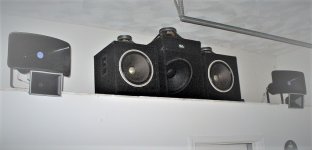
Some images are provided. One is a look at the loudspeakers, the rest are screen shots of foobar and rephase in both the front end and crossover machines to provide examples for the above text. Note that the mids/tweets are indeed aligned vertically, the woofers/sub placed in more acoustically advantageous positions for the room. Details in some images may be out of date, a reflection of how easily (and often) different things can be tried, but they serve their purpose.
The images are, in thumbnail order shown,
the loudspeakers
foobar dsp stack on front end
mux modular on front end
expander on front end
curve in convolver on front end, shown in RePhase
expander under test in VST Plugin Analyser, phase
dsp stack on crossover machine
convolverVST on crossover machine
convolverVST config file on crossover machine
midrange filter on crossover machine shown in RePhase.
5. Updates
8/26/20:
Since the original post, changes have been made. One was forced on me. That occurred when a brutal power outage with multiple 'flickers' took down my front-end machine's MBR, making it impossible to boot the system without a rescue stick. Through dos on the command prompt I could see that files appeared intact, but I could do nothing to repair the MBR, nor could any rescue medium I built off the net (having multiple computers can be a help). I even tried Geek Squad, who were helpless. Eventually the exact setup (remember where you put those config files; DOS isn't the best way to search for them) was recreated on a spare and nearly identical machine, leaving me with a dead spare (the original front end) which was wiped, reformatted and reimaged to a clean UEFI/GPT setup. MBR is probably still dead. I found that the MS ISO images refuse to load onto anything with MBR partitioning. How nice. But it's back up again, waiting for something to do, and the music system is back as good as before.
In fact, it's better. I decided to 'expand' my multiband expander from 10 to 17 bands (incrementally, first 12, then 15, then 17). The 17 bands each comprise about 0.58 octaves. Phase and magnitude linearization become touchier the more bands you add; the current model has swings to +/- 4*, though the majority of the usable frequency range is less than +/- 3*. I also decided upon the oddball 256.4ks/s sample rate since that gives the best distortion figures, and it's doable with Sox resampler and RePhase filters. The result, despite worse (but still not bad) phase characteristics, couldn't be ignored --- the pluses of shorter frequency bands outweighed the minuses by a good deal. It sounds better than ever, and I know this because I still have every expander config I've made, each with its own long babbly title, and can A/B with the earlier models. It was worth every hour. How I wish my sound card hardware had arbitrary sample rates too, but Sox is so good it's pretty much a wash. The improvement is stark, in fact. Even a few vocal recordings that seemed hopelessly sibillant are smoothed considerably without resorting to notch filtering. And to minimize the amount of resampling I reran my 'room curve' on rePhase at 256.4ks/s also. It's endless hair-pulling and endless fun.
All processing is an artifice anyway. The major 'trick' to removing artificiality from expansion appears to be the narrowing of bands. At a point this collides with less manageable phase at least on reaxcomp (which is, after all, a freely-offered plugin).
9/19/20: Major change made to hardware. Remarkable results. See post New Horn in Town? for details and photo.
Attachments
-
 speakers_cropped.jpg98.3 KB · Views: 605
 -
 foobar_prefs_fe_crop.jpg151.7 KB · Views: 489
 -
 foobar_mux_fe_crop.jpg144 KB · Views: 462
 -
 foobar_reax_fe_crop.jpg156.7 KB · Views: 462
 -
 rephase_fe_crop.jpg174 KB · Views: 467
 -
 VPAreaxphase_crop.jpg161.2 KB · Views: 114
 -
 foobar_pref_xo_crop.jpg102.9 KB · Views: 94
 -
 foobar_conv_xo_crop.jpg103.6 KB · Views: 71
 -
 convolverconfig_crop.jpg95 KB · Views: 69
 -
 rephase_mid_filt_xo_crop.jpg143.8 KB · Views: 86
Last edited:
Pano, I am as baffled by this as you. 
But I certainly give leoman an "E" for Effort.
TBH, I suspect an Astrological Joke here.
Leo Horoscope: Leo Zodiac Sign Dates Compatibility, Traits and Characteristics
Right on the cusp of July 23. Leo. Geddit? This could only happen in the Lounge.
But I certainly give leoman an "E" for Effort.
TBH, I suspect an Astrological Joke here.
Leo Horoscope: Leo Zodiac Sign Dates Compatibility, Traits and Characteristics
Right on the cusp of July 23. Leo. Geddit? This could only happen in the Lounge.
And the dry humour... 
leoman said:One could always leave the amp boards sitting around naked...
Aw, I thought this thread would have "legs" in the Lounge... 
It's a bit Rube Goldberg isn't it? Or what we older Brits call Heath Robinson...
Does it work? Does your Wife like it?
It's a bit Rube Goldberg isn't it? Or what we older Brits call Heath Robinson...
Does it work? Does your Wife like it?

Amazing, boswald. You and leoman are practically next door neighbours! Are you drinking buddies? 
We used to have an electronics junk shop in Fareham, Hampshire about 20 years ago. Irresistible to a geek like me!
Found some Eminence Beta 8-A woofers there for £30 the pair.
I lugged these heavy things back to London. I don't make this up. Next day there appeared in our street a pair of empty Wharfedale Linton cabinets:
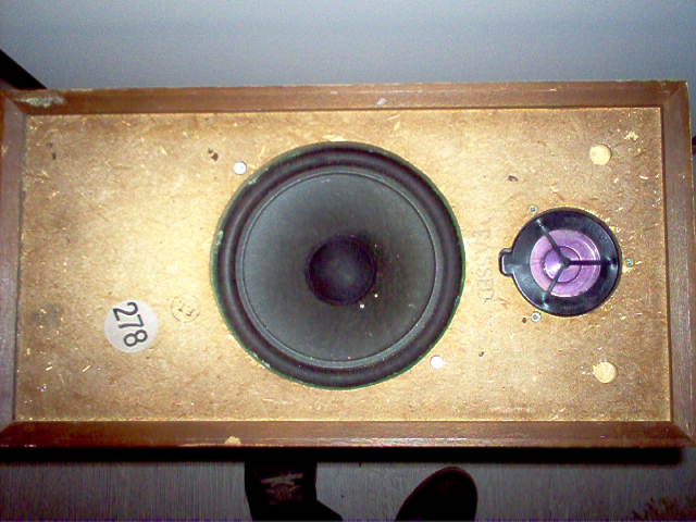
The rest, as they say is History. I built the baddest, loudest speakers in the Street. My ex took them after our divorce. But I hope they are still working.
We used to have an electronics junk shop in Fareham, Hampshire about 20 years ago. Irresistible to a geek like me!
Found some Eminence Beta 8-A woofers there for £30 the pair.
I lugged these heavy things back to London. I don't make this up. Next day there appeared in our street a pair of empty Wharfedale Linton cabinets:
The rest, as they say is History. I built the baddest, loudest speakers in the Street. My ex took them after our divorce. But I hope they are still working.
The attenuator pots I mentioned in the post came out of a bag 35 years old full of surplus dual/mono pots, best I ever used. They've been used in everything I've made since. Not one has ever scratched even when turned for the first time in a decade. Cost me $1 (fill a bag for $1) at an electronic surplus place in Woburn. My friend and I used to drive there at lunch from RCA in Burlington.
Sorry Steve, I missed a post of yours. Yes, it does look Rube Goldberg. BTW the downfiring speakers atop the 3 bass enclosures are the original drivers, used for nothing more sophisticated than added weight. It also works well. Sounds exactly as good (or bad) as my programming of its input. At low levels it sounds like a pair of perhaps AR3s but better. At higher levels it sounds positively live on well-recorded music. The expander makes a good contribution to that effect. Vocals (solo to chorale) are natural. Resolution is the best at least I've ever heard.
ii. Why Expansion?
Dynamic expansion is something I've always liked. I built expanders in the 80s for my analog system. The problem being served is that most loudspeakers, microphones, anything mechanical, will impart some sort of compression to recorded sound.
Having gone out of my way to measure this, in both directions, I can say this is simply not true until you hit the very limits of the transducers. I'm talking about hitting a 1" compression driver with a 70V RMS sine tone here, which is abusive even in the PA world.
I can promise you that compressors set by sound engineers are to blame for any compression you hear.
I'm glad you've found something that improves the sound for you, though.
Chris
Leoman, how are you able to use Atlas CJ-46 horn down to 200hz when the datasheet freq response clearly shows that it's good around 700-5khz?
Hello noviygera, I saw the same graph you saw but also saw horn loading to 115Hz so I decided to get a horn and test it (I already had the drivers). I had been using University Cobreflex II horns at 340 Hz (well below the 400 or 450 University had used in their Classics) and was looking for a horn with lower cutoff. What I saw actually stunned me. There was mild smooth rolloff on good-looking sine waves as I went below 300Hz with the Atlas, but I didn't expect to get to <180Hz prior to seeing the sudden appearance of what looked like 2nd harmonic (or possible reflection? It's been over a year) appear on the scope, though that was not audible. I immediately ordered a 2nd horn. I decided to use 250Hz to leave slack for complementarity, but found that the setup simply sounded better at 200Hz. The rolloff was easily manageable in the crossover curve.
I don't know how to explain Atlas' graph except to suggest that perhaps at 15W, which I doubt I ever approach, things are different? My 'listening area' is about 45'x28'x12' but I use very little power to drive them up to uncomfortable levels for me. My shelving is done with a mike and scope, and things are pretty smooth on sweeps. I know that the horn is marketed and heavily used for applications not generally employing crossovers or other speakers, so I'm quite certain it produces strong output well below 700Hz.
Chris661, I'll take your word for that. Experiment is always better than literature anyway, IMO.
Last edited:
...how are you able to use Atlas CJ-46 horn down to 200hz when the datasheet freq response clearly shows that it's good around 700-5khz?
It is a long horn with a small mouth.
The driver is well-loaded down to 200Hz. But the directivity does not come up until 500-1kHz.
If you use it outdoors, the 200Hz goes all around and is lost.
Indoors the lows are contained and propagate quite well.
My first objection was "2 feet of path length!!" However when I saw it was digital-heavy then I knew this could be compensated trivially (not like my old days with long horns).
The driver is well-loaded down to 200Hz. But the directivity does not come up until 500-1kHz.
If you use it outdoors, the 200Hz goes all around and is lost.
Indoors the lows are contained and propagate quite well.
.
Probably the reason the transition from the cone Altecs to the mid horns is so seamless. At 200Hz the Altecs should be far below the point at which they start to beam. So it's a good match.
- Status
- This old topic is closed. If you want to reopen this topic, contact a moderator using the "Report Post" button.
- Home
- General Interest
- Everything Else
- An Unorthodox and Affordable 1st Class System
 Thread moved.