Understanding NFB into LTP

This is my 6J6-based LTP. For the time being, try to overlook the tail, cathode, and plate resistors - I'm still working out bias and balance after scrapping the CCS.

My question is about NFB, which is coming in via the 8k2 and getting divided by the 100R. That's only pushing 1.2% of the OT signal into the lower grid. For comparison, Fender AB763 uses 820R and 47R for about 5.5%.

The question is, if I want to increase the NFB, should I reduce the 8k2, or increase the 100R? The former would put more NFB onto the tail resistor, while the latter would push up grid and cathode voltages (albeit only slightly). Or should I drop them both down ala Fender? Is there a best practice here?

AJLKRge.png

my no name speakers with bassreflex suck

after some listening and comparing bass reflex speakers (the one with the hole) and fully closed i must say that the bass at bass reflex is really rubbish.

the bass goes at 1 and only frequency loud and you do not hear any other bass frequencies because they are not audible. it is really boring to listen to.

what is your experience? do you like bass reflex? or is it a common knowledge that it sucks?

________________________________________________________________________________________________________

:cop: Moderators Note: The title of this thread was changed around the time of post #36, from "bass reflex sucks", as it didn't convey the topic well enough according to e3k. :cop:

Blown Tweeter replacement with unknown crossover

Hi all,

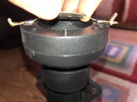
So a while back I picked up two speakers second hand, from what I can work out they're custom built and probably minimum 10 years old. Recently had a party and a drunk friend turned on the mic mid-set, massive feedback loop and tweeter on one speaker completely gone.

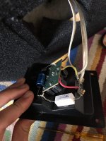
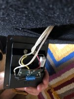
Have opened it up and was hoping the tweeter would have a model No. or something but the entire loudspeaker seems to be unbranded. Am wondering what the best way for me to determine a replacement would be? I'm like 90% sure that each loudspeaker is 8ohm impedance and 300W but thats all the information I have.

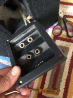
I've attached pictures of the broken tweeter and the wiring on the crossover, also something that has caused confusion to the few people I've shown it to. So far have not managed to work out what the use of the jack inputs is, as have just been hooking it up to amp using speaker wire.

Also while here, as there was a huge surge due to mic and damage to speakers, is there a chance that the amp could be damaged too? and if so is there any way to check? from what I could work out through testing it sounds pretty ok.

Attachments

  • IMG_0049 copy 2.jpg
    IMG_0049 copy 2.jpg
    503 KB · Views: 153
  • Crossover back 2.jpg
    Crossover back 2.jpg
    557.5 KB · Views: 159
  • crossover back.jpg
    crossover back.jpg
    552.8 KB · Views: 155
  • Outside back.jpg
    Outside back.jpg
    619.6 KB · Views: 141

Line Level Output Denon AVR-E300

My Denon AVR-E300 does not have pre-outs. I'd like to add pre-outs so I can use the receiver as a line source for my active speakers.

Is there a way to bypass the amplifiers to create pre-outs?

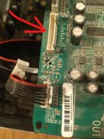
The digital board with the DACs has a plug that might be a candidate. Also, the amplifier board has white plugs next to the pots. Are those pre-amp line sources Denon built in but didn't connect because they saved them for their higher end receivers?

As an amplifier this receiver is useless to me. If I could remove the entire amplifier and just run the receiver as pre-out/pre-amp only I'd be a happy clam.

Attachments

  • ink.jpg
    ink.jpg
    227.3 KB · Views: 137
  • ink2.jpg
    ink2.jpg
    347.1 KB · Views: 138

Primary on Dyna PAS fried after increasing heater voltage to 12.6v

I installed a new voltage doubler to power the signal tube heaters, that used schottky diodes. A few days later, the primary melted down. Nothing connected to the secondaries was damaged. Post mortem, testing with an external supply, currents still seem in spec (600ma for all 5 tubes)

Simulating, I noticed spikes as high as 6 amps in the heater secondary, though using generic silicon diodes instead showed similar spikes. Could that have fried the transformer, or was it a coincidence?

Bose - amp 3510 C5

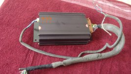
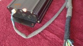
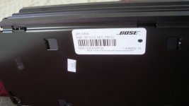
I have a Bose - amp 3510 C5 - AUDI A6 OEM Bose Amplifier 265 030a 3510 C5 (found as "Bose R12" on some sites) I think the pinouts for 25-pin plug are the attached but I don't know what's connected to 4-pin plug.

Any diagram / service book / pinout details ?...

Attachments

  • bose connector-06-the correct one.jpg
    bose connector-06-the correct one.jpg
    42.8 KB · Views: 2,751
  • Bose 4 pin connector-00.jpg
    Bose 4 pin connector-00.jpg
    286.9 KB · Views: 2,004
  • Bose 4 pin connector-01.jpg
    Bose 4 pin connector-01.jpg
    262.2 KB · Views: 1,317
  • Bose 4 pin connector-03.jpg
    Bose 4 pin connector-03.jpg
    171.6 KB · Views: 2,280

Speaker to mic to Amp return testing

Simple test to check speaker and its direct frequency spectrum via amp return with my cinema THX crossover monitor.

I matched the levels so they appear the same the mic distance I can alter it, move it closer inwards or move it further back place another mic near to bass reflex port along with mic directly on axis with JBL 4647, centre channel LF JBL 2226.

I can see the amp return direct showing the LF range I can alter the Behringer DCX2496 crossover and watch the freq spectrum changing.

I had a lead patched into the computer with few alligator-clips to the 3.5mm jack. One output to input was the microphone the other output to input was the THX monitor amplifier return, good as if I connected that directly to the amp it blow the computer up.

I opened two windows of TrueRTA as I was using an audio mixer preamp for the Behringer ECM8000. One window TruaRTA for left channel Amp return and second window for TrueRTA right channel microphone.

I can measure the speaker vs its power input.

Attachments

  • 117764673_10158462158115149_1651675669911671384_o (1).jpg
    117764673_10158462158115149_1651675669911671384_o (1).jpg
    71.7 KB · Views: 108
  • 117806372_10158462166235149_6387436459077477574_o.jpg
    117806372_10158462166235149_6387436459077477574_o.jpg
    48.3 KB · Views: 112
  • 117827847_10158462169255149_5051607123127009847_o.jpg
    117827847_10158462169255149_5051607123127009847_o.jpg
    89.5 KB · Views: 106

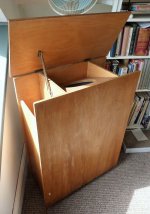
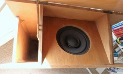
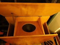
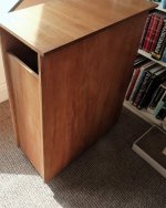
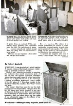
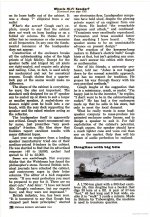
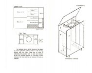
Is the Gough´s Speaker a transmission line?

Hello,

i found this Gough´s speaker enclosure and i love the concept of refletion of the sound.

but im wondering if it will sound good and if its worth to build one

its a transmission line?

because has a paralell tube but it has no stuffing


somebody heard one of this cabinets?


here is a website dedicated to this cabinet:
History - GOUGH SPEAKERS ARCHIVE


and here two videos video of one :

All hail Jabez Gough and the 1957 vacuum-tube hi-fi - YouTube

Old-school hi-fi with a Gough speaker - YouTube

Attachments

  • Vintage-controversial-Jabez-Gough-reflecting-loudspeaker-excellent.jpg
    Vintage-controversial-Jabez-Gough-reflecting-loudspeaker-excellent.jpg
    311.9 KB · Views: 284
  • Vintage-controversial-Jabez-Gough-reflecting-loudspeaker-excellent-_57 (2).jpg
    Vintage-controversial-Jabez-Gough-reflecting-loudspeaker-excellent-_57 (2).jpg
    188.4 KB · Views: 320
  • DSC05039.jpg
    DSC05039.jpg
    56.9 KB · Views: 283
  • Vintage-controversial-Jabez-Gough-reflecting-loudspeaker-excellent-_57 (6).jpg
    Vintage-controversial-Jabez-Gough-reflecting-loudspeaker-excellent-_57 (6).jpg
    434.2 KB · Views: 274
  • content (2).jpg
    content (2).jpg
    639.9 KB · Views: 272
  • content.jpg
    content.jpg
    555 KB · Views: 143
  • content.png
    content.png
    308.8 KB · Views: 142
  • image028.jpg
    image028.jpg
    68.7 KB · Views: 162
  • PlanRear.jpg
    PlanRear.jpg
    144.8 KB · Views: 182
  • image036.jpg
    image036.jpg
    42 KB · Views: 192

Pioneer TX 9500

Hi all,


apologies if this topic has been discussed before but a quick search in the forum did not bring anything relevant.


A few days ago I acquired a beautiful and fully working Pioneer TX 9500 tuner. It has all original electrolytic caps, therefore I am planning to recap the power supply and audio frequency boards. Not too sure about the MPX and IF boards yet as I don't have the equipment for an alignment.


I have noticed that the audio board has tantalum capacitors in the signal path. Initially I thought about replacing them with Nichicon FG series. Unfortunately due to their values, film capacitors would not physically fit.


Given that tantalums are low leakage capacitors, it might be reasonable to replace them with low leakage Nichicon KL series, or just leave them alone. I know that in all vintage Pioneer amps they used to have tantalums everywhere in the signal path and usually they get replaced with electrolytics, but I am debating with myself on this. I am assuming that the Pioneer engineers used them there for a reason (stability, low leakage etc).


Please let me know your experiences all vintage restoration gurus out there.

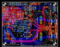
My new monobloc layout for Mauro Penasa's MyRef Rev. C

Its been a while now since I first laid out a PCB for Mauro's "My Reference" revision C. The first layout was largely a product of taking Mauro's suggestions for a monobloc version and running various iterations past the forum to get as much input as possible.

Well since then literally hundreds of people (maybe more I do not know) have built or are building MyRef. This has given me even more feedback about the layout and spawned some new ideas. Also Mauro has given some guidence on how to make the circuit, and the layout a little better. I have taken this new experience and applied it to a new layout. Here it is for your pleasure.

Major changes:

1) More flexible input and led interfaces allow for terminal blocks, pinheaders, IDC connectors, etc..
2) Bigger more flexible cap space to allow for MKP cap on input.
3) Allowance on power supply for monoluthic rectifier (as in the original) or TO220 types such as MUR860.
4) Additonal output solder holes for direct soldering of large gage wire to the PCB for OUT and OUT-GND.

You can still build the circuit exactly as before, or take advantage of the new features, its your choice. You can also still build the circuit as "Rev A" without much fuss.

Also, the layout has been changed to eliminate as much as possible any sharp angles in the traces. This may not do anything, but I like it better. 🙂 Also many traces are widened, and some little things like silkscreen changes have also been made.

Only circuit features which adhere to the circuit designer's philosophy and intent have been included in the layout, and nothing else ever will be included by me as the circuit is in my opinion, simply put, often imitated, never surpassed. 🙂

Thanks to Mauro for a design which will forever change the way we look at chip amps.

Note: This is the 2 side version which Brian and I have produced, but I am working on a single side version which I will make PDFs for and share freely so those who would like to etch it for yourselves can.

Here it is:

Cheers!
Russ

Attachments

  • pic.png
    pic.png
    75.4 KB · Views: 6,467

Quarter wave enclosure for Dayton RSS265HO-44?

I've tried this driver in small sealed and ported enclosure and not gotten great results.
Would like to try a quarter wave design but with 90 degree angles as I am rubbish with woodwork. Think Homer's spice rack.
Qts is .45 and vas is 1.25 cubic feet. Would this work in this type of enclosure? Don't want it to be too big but could do tall and narrow. Depth im not too worried about either.
One other thing. I have two of these so would a dual sub be better?
Its primarily for music. I don't do any more than 2.5 channels. It will partner with full range drivers and 10 inch woofers as mains. I have about 400wpc stereo sub amp to.power it/them.
Any guidance would be much appreciated!
Cheers
Peter

need advice on adding a turntable to existing home audio system

Hello, all. Complete noob here so please bear with me if I'm asking rudimentary questions or if I'm posting this thread in the wrong forum altogether.

I recently acquired an old Panasonic PL 530 turntable. I'd like to hook it up to my current system which includes a JVC RX-D206 receiver and a couple of vintage Kenmore speakers (circa 1970). Here are my challenges in getting this set up working:

1.) Due to the configuration of our living room and speaker/AVR setup, the record player needs to live about 10 feet away. The 2 foot RCA cable coming out of the turntable will need a 10 foot extension cable. This alone I think possible maybe calls for a preamp to boost the signal but I don't really know.

2.) I tested the turntable out on the receiver to make sure it'd definitely putting out a clear phono signal--it is. Although there are a few different available RCA inputs on the receiver, the only input that worked was the RCA input labeled "TV". The volume level output sounded a bit low, TV input is already dedicated for use by the television. Not sure whether or not I need to get a new receiver with a "Phono" RCA input, but if at all possible I'd like to avoid having to buy a new receiver.

Thoughts? Advice? Thanks!

Dukane Exponential Horn

Removed this horn from a field house installation we did so I thought I would play around with it. It had a Dukane 1" driver to a 1.4" throat adaptor to a 2" exit throat on the horn. So I threw a 18Sound ND2060A I had laying around and put it on top of a couple of our custom boxes with 18 Sound 15ND9400s, I disconnected the BMS 4594ND mid/highs that are in the box. Biamped it with a xover @ 800Hz/24dB and the thing sounded really impressive. If you walk around out of the pattern it just went away really nicely. The horn feels like a plastic material, not sure if Dukane made these or somebody made them for them.

I don't think my wife will let me set this up on either side of the TV for the Pats game this weekend though.

Attachments

  • IMG_0793.jpg
    IMG_0793.jpg
    825.6 KB · Views: 245
  • IMG_0796.jpg
    IMG_0796.jpg
    717.7 KB · Views: 228

Crown Amcron DC300a help.

Good morning gentlemen,i wonder if some of you could assist with this project..i know these DC300a's have been covered before,but i cant find anything relating to my problem in those threads...i have a DC300a here, circa 1973/74,With an issue...no sound! i have recapped the main board, checked every transistor and diode,checked every resistor (and replaced some out-of value ones where required)...have fitted a new 739 ic,but still the same problem.

Powers up, have 0.00v and 0.01v DC on outputs,so all ok there. I have the correct voltages at the diode pump (90v) But no audio.

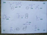
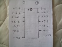
I have sent the voltages i am getting on the main board,clearly Q120,Q102,Q220 and Q103 are incorrect.

On the chip,i should be getting 1.35v at pin 1,but i have -2.8v,so something is clearly amiss with this board. I have checked the pcb tracks carefully,there are no breaks or cracks. but now i'm stuck....would appreciate any advise on where to look now.

Attachments

  • 100_3059.jpg
    100_3059.jpg
    326.1 KB · Views: 211
  • 100_3056.jpg
    100_3056.jpg
    365.6 KB · Views: 211
  • 100_2998.jpg
    100_2998.jpg
    332.2 KB · Views: 210

New Snell C’s

eBay for $200. Needed woofer surrounds. Refreshed the tweeter’s ferrofluid. And my God was Peter Snell a genius or what? I’m a Snell fan (Type 1’s, K’s, Elll’s, J’s) and he NEVER disappoints! These C’s are awesome. I bought them to give to my sister. And after listening to them, well, I’m happy there are just down the road. And I am still in love with my Snell Type 1’s.

Attachments

  • 5755E5A5-2C55-4317-BC77-0918ADF89E77.jpg
    5755E5A5-2C55-4317-BC77-0918ADF89E77.jpg
    1,018.6 KB · Views: 146

Line Magnetic LM-508ia - Affordable high power SET amplifier

After my last experience with relatively high power SET amplifier (see https://www.diyaudio.com/forums/tubes-valves/327637-lian-845-set-kit-commercial-product.html ), I started thinking about upping the game and getting into power range comparable with push-pull tube amplifiers. There are two ways get there — either use high power tube like 833 or using tube in A2 class where grid gets positive in relation with cathode.

Tubes like 833 require even higher voltages than 845 or 211 and very high output impedance requires extraordinary effort to make output transformer compatible with it and still have enough bandwidth for full range audio. That will result in very expensive design, with a lot of full custom components. Example of that approach is WAVAC 833. But for the $350K price results ( Wavac SH-833 monoblock power amplifier Measurements | Stereophile.com ) are not very impressive.

A2 class though can allow lower plate voltages with higher current, thus reducing requirements to power supply and transformer design. Load impedance 4-6K ohms is very much achievable without extraordinary effort. With output tube operating with grid current you need to have low impedance driver circuit. Easiest way to achieve that is using cathode follower with direct connection to grid of output tube. It is possible to use 845 or 211 tube that way, but there are also other tubes which were design to have grid current almost at all signal levels. One of examples is 805/838 tube. The only real difference between them is that original 805 had a plate cup, and 838 did not. Today China makes 838 equivalent, which for some reason they call 805. Thus when you buy a new production 805 tube, you are getting 838. Of cause neither of these tubes is really affordable as NOS — they almost all gone and were not manufactured outside of China for decades.

I didn’t want to do build from scratch and just like with 845 based amplifier I referenced above, I decided to get a modern Chinese amplifier and start from there. Line Magnetics is a mid-range Chinese brand which builds and markets tube amplifiers all over the world. They have amplifier based on 805 tube which is claimed to reach 48W of output power. Price (if you buy direct from China) is in relatively affordable range, even when one account for international shipping charges. And finally I made a move and placed on line order.

After 3 weeks of waiting UPS guy knock on my door, and when I opened it, large cartoon box was sitting next to it. The box has some signs of tear, which is explainable (it“s path was from mainland China to Honk Kong, to Japan, to Chicago and finally to Dallas). But when I opened it — everything inside was in pristine shape. Tripple boxing and attention to packing details did the job.

One note — when you buy direct from China, you likely getting the version that requires 220 volts power line. Some devices can be modified to use 120V, some are not. From what I read about Line Magnetics gear, I thought that I will be able to easily convert it with s bit of soldering around power transformer. But I also had a boost transformer, which I purchased many years ago, but never put in service. Thus I was ready to use amplifier out of the box too. As alternative, you can arrange 240V outlet in you music room — many audiophiles have it already. If you do not, getting step up transformer is much cheaper than hiring electrician. In the end I found that my version of amplifier (made some time in late 2019) does not allows easy voltage change, and I kept it running with boost transformer. But to use in my high-endish music room I bout another transformer, which simply looks more in place (UMI Step UP 110 to 220 Voltage Converter found on Amazon). It is rated for 1200VA which is well enough for amplifier that consumes 500W.

Line Magnetic LM-508ia has excellent fit and finish. Designers had clear attention to details and manufacturing quality was excellent. All chassis is covered with mirror like enamel probably ½ mm thick. Connectors for inputs and speaker outputs are of high quality. Amplifier came with pair of Line Magnetic branded Chinese 805 tubes, pair of also LM branded 300B tubes (used as drivers), pair of new production Electro-Harmonic 6SN7made in Russia, and a Chinese 6N9P (equivalent of 6SL7) tube of unknown brand. Later we will see that this amplifier works best with tubes that came with it from the factory.

LM-508ia has two adjustments — output tube current and hum balancing. When I turned it on, both of these adjustments were spot on. It only can be explained if each unit is tested and adjusted right before it is packed into the box.

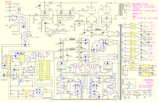
This amplifier has simple classic circuit (see Pic.1) : there are two stages of amplification which are classic resistor amplifiers with half of 6SL7 and paralleled 6SN7, loaded with 300B as cathode follower directly connected to grid of 805 tube. The latter has relatively low plate voltage, and grid is positive at idle. 300B operates with negative cathode source and idle current at about 40mA, while output tube is biased to 120mA of plate current. All that results in constant power consumption of about 500W. Power consumption does not change while you play music — this amplifier really operates in A class. Al power sources use solid state rectification and CLC filtering. Circuit includes timer that delays high voltage until all tubes are warmed up. Additional digital circuit is used for remotely controlled volume pot. I used this unit as pure power amplifier and thus remote control was put back in the box until I decide to sell it.

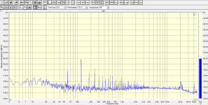
LM-508ia has three regular inputs, which can be selected with front switch and affected by volume control, and fourth input that bypasses volume pot and designed for use with per-amplifier. Unfortunately the circuit does not change and all gain stages are used in either case. Thus the only advantage of using fourth input — it ignores volume control setting. But noise/him level stays the same regardless of which input you use. Like almost all tube amplifier, this unit has some hiss and noise at the output which can be heard through speakers when you are close to them (my reference solid state Bryston is dead quiet in comparison), but I didn’t hear any hum from my sitting position 8 feet away. I measured AC noise at speaker and it was below 2mV. Main type of noise is random hiss and some hum like sound from 60Hz power line frequency and its harmonics. Pic.2 shows spectrum of noise as it was measured by me.

Before putting amplifier on my workbench, I decided to play few records with it. The result was generally positive. It plays loud enough through my 89db/W speakers without obvious signs of clipping. Overall sound was something between my 845 based amplifier (it was not as soft) and solid state Bryston (LM still played like tube amplifier). There is one more setting switch available — it adjust amount of global negative feedback to listener“s liking. Unlike A1 class amplifiers, this amplifier needs some amount of negative feedback to reduce distortion and output impedance to make it compatible with modern speakers using complex crossovers. I initially use 8 ohm output and least amount of feedback (almost none), but bass was uncontrollable. Increasing feedback to second position improved sound significantly. I also tried to use 4 ohm outputs and like it more. In the end the best for my speakers was 4 ohm output and second setting of feedback. When I tried to increase feedback, bass became even tighter, but overall sound stage started collapse. It is clear why variable feedback feature was included — make amplifier work best with various speakers.

>>>see follow up below<<<

Attachments

  • Pic.1-LM-508IA-SCH.png
    Pic.1-LM-508IA-SCH.png
    382.6 KB · Views: 1,329
  • Pic.2-NoiseFloor.png
    Pic.2-NoiseFloor.png
    144.4 KB · Views: 692

Help with Sony SRT-V3 output transistors and emitter resistors

I recently received a free Sony SRT-V3 with some sentimental value. The unit did not power up. Opening it up I noticed the primary 4a fuse was blown. The fuse appeared to be a fast blow fuse. I replaced it with a slow blow and now the unit will power up. Now when turned on, the two emitter resistors (R725 and R726) glow bright. R725 is cracked and starts to smoke. The other two emitter resistors (R774 and R775) both test .01 on 20kOhms.

I'm trying to test components and remember classes from 25 years ago so please forgive my limit understands.

I tested the output transistors on my diode setting and Q713 is shorted, Q714 tests 066 both ways, Q764 tests 459 (black on base) 687 (red on base), Q763 tests 504 (red on base) 637 (black on base).

I'm wondering if I can get feed back on how I see things?

Seems obvious that the R725 and R726 need to be replaced. I believe R774 and R775 need to be replaced as well. Q713 needs to be replaced. I believe the other three output transistors need to be replaced. From what I understand PNP and NPN should not give readings both ways and voltage should read between .45V to .9V.

Am I correct in how I'm understanding my testing?

Lastly, where is a good site to go to to find replacement compontents? I've discovered el-component for replacement part numbers for the output transistors but I can't find anything to help find replacement MPC resistors.

Thanks in advance for any advice, feedback, and gentle insults.

Sympatico amplifier - impressions?

I am thinking of buliding stereo (later active) 2 way system for my friend, using Sympatico amplifier modules. It will be feed through balanced connections with DAC/preamp or miniDSP. Since I have not get yet any listening experiences using LM4780 in such configuration, I am asking Sympatico builders about their opinions about this project, which loudspeakers are you using and how far should I put sound performance expectation?


Thanks in advance.

EL84 and 6V6 in parallel???

Hello everyone,

I've been working on some simple single ended guitar amp designs over the past few months and I really want to try running a 6V6 and an EL84 in parallel for the power amp section! I've drawn a rough schematic and attached it to the post, so can someone take a look real quick and let me know if I'm on the right track and if this can be done?! I know I'll need an ideal primary impedance of 3000 ohms on the OT, but the hammond 125ese can be had with a 2500 or 5000 primary so that should be close enough right? As I said before the schematic is purely conceptual, I haven't breadboarded anything yet, I just want some people's opinions on whether this can be done with no issues and also if there are any recommended changes to my design.

Thanks for your help and comments in advance!

Attachments

Netflix, The Social Dilemma, is the most important documentary of our times

Remember how the people who invented the atomic bomb came out later saying that they regretted it. I was reminded of that after watching the creators of social media interviewed in "The Social Dilemma" now available on Netflix. I found it terrifying. It is not perfect or anything, but watching the people who built the machine describe how it works and what it is really doing is a must see. I have worked in software for many years, I had only a vague idea of what was going on. It is too long, and too polished, but that may appeal to the widest audience. If you have ever spent time developing an algorithm that optimized something, you understand how badly single parameter blind optimization can go wrong. Imagine how long it would take an optimization algorithm with the only goal of maximizing the acceleration of a car to figure out that running into a solid wall gives the peak acceleration. Look around at your family and friends and see if you can pry them away from social media for a day. Go ahead and try. Turn off the internet at your house, you will find yourself alone in a few hours as the others go find internet elsewhere. Remind you of a gambling addiction?

Can get negative voltage from HD Plex 300

Hi guys, I need your advise, for a project I need +5v gnd -5v, I have a HD Plex 300w power supply and I´d like to use it, but it only give + voltages.

Do you know if there is a way to get a negative voltage from any where inside that psu?

I know I could do it with an oscilator, diodes and capacitors, but could be more elegant just to get it from psu.

Thanks,

B&G Neo 3/Pdr fails

I was constructing a new metal plate for a test. and took another look at the B&G neo 3 PDR.
Why are they so efficient and why do my measurements of them look so bad?

well here is the answer. i dont know how old they are to be honest.

RECTIFICATION! , i say somewhere 1.5 Khz at 1 watt. that should be 2.85 volt. in this case being 4 ohms ~ means 2 watt.
- i say it distorts insanely at 1.5khz.. it is actually 3 Khz..

Common B&G Neo 3/PDR Planar Tweeter failures - YouTube

Audiostatic, dot problems

Recently I rebuild a pair of Audiostatics ESH100. An almost full range electrostatic with integrated bass reflex for the lowest octave.
Listening to the end result I noticed that one of the ESL's had a lower output and that when playing louder distortion is occurring sooner than on the other one.
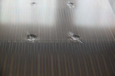
To stabilize the diaphragm Audiostatics applied silicon dots between the wire stator and the diaphragm. Upon inspection it turned out that on the low output speaker the silicone dots were much bigger than on the other one. And what's more it looks like the dots are sucking the diaphragm closer to one side of the stator. The pictures are showing clearly that the silicon sealant is producing dents in the diaphragm. In my opinion caused by shrinking of the sealant.
I would appreciate to get some help about alternatives, like advice about non shrinking (clear) silicon kit or paste, the use of double sided foam tape or perhaps the use of kneadable rubber/putty.

Attachments

  • NW_IMG_2350.JPG
    NW_IMG_2350.JPG
    53.9 KB · Views: 247
  • NW_IMG_2351.JPG
    NW_IMG_2351.JPG
    62.7 KB · Views: 245

ALD's Double Inverted ChipAmp

Howdy Neighbours,


Just fer giggles, let's try this:


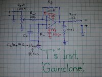
'T.s' invrt.  GC.jpg


..puttin' the DIY BACK into diyaudio...

Hun, so this is a REcreation of " "T's" Inverted GainClone ". It obliviously wasn't his, but rather somebody took his idea of an inverted gainclone power amp and thru a pot on the front ...

:Ouch: :cuss: :warped: :bfold: :scratch2: :idea: :Ouch: :stop: :whazzat: :scratch2: ... :idea:

Doh! [1st Task: why is this 'amp' unstable? ]


So I recall T noting (re his power amp) that using an opamp [no matter signal or power] in invert. config. has some advantages:


A) You can choose the values on the +input so they match the -input's (better balance; tweak by actual measurement)

B) Invert. operation provides that nifty virtual ground that, because of the fet input, physically ACTS almost IDEAL [acting purely mathematical, with no real-world 'fudge' factor] and thus has these tech. advantages ... blah, blah, blah, ... I can't recall what he said.

...oh, oh , and I thought:

C) Well, because [in this particular case] the pot sets the input impedance, Rin and Rf can be dropped by an order of magnitude to provide better noise and more current through the resistors [and junction] that provides further benefit by ... blah, blah, blah, I can't recall what I thought. ;}

D) So I'd like to correct and develop this circuit and build it and do some basic testing and listening and ... and, d o i t m y s e l f , ... if ya know what I mean ...


Cheers from the

ALD

man!

PS And YES that's how yer supposed to spell n e i g h b o U r s!!11!1!

PPS It's not DOUBLE inverted .... Yet!

PPPS This project wasn't getting much traction in the Loungy thread sooooooooooo ..................

Portable hifi speaker

I'm new to diy speakers, only starting down this rabbit hole a week or so ago. I want to build a high end portable bluetooth boombox. Something that will wow me and my family that I can bring along when we go on trips or parties.

This is my list so far
Monoprice Premium Bluetooth 5 Transmitter & Receiver- for the bluetooth
minidsp 2x4 hd - using it as crossover
ICEpower 50ASX2SE - for the tweeter and midrange
ICEpower 125ASX2 - for the woofer

Drivers
ScanSpeak 15W/8530K-00 - midrange
ScanSpeak Illuminator D3004/6040-00 or the be version if that is worth the extra 200$
not exactly sure what woofer to get

Currently considering passive radiators or ported but not entirely sure what the advantages and disadvantages are. Also considering just using a predesigned center speaker and modifying it somewhat to make it bluetooth and portable.

Correct Sealant Glue I Need

Hi and good morning all
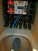
ive aquired a pair of B&W DM305 Floorstanders and 1 of the prism back panels vibrates at certain bass frquencies ive taken the driver out and can see that B&W only glued them top and bottom of cabinet to the prism piece and not to sides which seems to be where the vibration occurs ive taken a pic of original glue but not sure what it is or what i could use instead to reseal the sides inside to try and stop vibration. Obviously i need a longish nozzle to be able to get inside cabinet and reach past prisms to reach sides.
Any help would be appreciated

Attachments

  • IMG_20200926_223206.jpg
    IMG_20200926_223206.jpg
    400.3 KB · Views: 107

I suppose I should introduce myself :D

I thought I'd finally say hello 🙂

I'm a complete novice & beginner but also curious - which can be a very annoying combination for experts. Why? 😀

Creating a small headphone capable DAC/Amp is on my list of things todo, which according to the Mrs is long and involves completing the new Koi pond first (13,000 litres or 3434 US gallons) that is taking my spare time, and should be complete sometime next year. However as winter sets in - it limits the dig/concreting that can be done so I start thinking of next thing on the list..

Last december I looked at the soekris DAC and this this year I've been researching Marcel & Naughtiboy's tube DACs as a comparison. I have to say it seems more attractive from an implementation POV plus the tubes should keep me warm in winter!

I have an old pair of Castle Harlechs (v1), Musical Fidelity A220 and a Myryad MC100 CD player that doesn't really get much of a play now days compared to the Mac and headphones. Not high end, but quite class-A with the A220 and Myriad being 'A-biased' AB.

I've been in software for over twenty years, ranging from embedded (Z80 to ARM and Blackfin) through FFT based GPU based image processing and deconvolution using FIR etc to quantum computing and cryptography (the day job).

Music - I tend to be open minded, although I play guitar and drums badly since school. I still have my old Fender Strat '88 and listen to a very wide range, probably a good example of my eclectic collection 🙂
* Opera - Puccinni arias mainly
* Stanton Moore - All Kooked out, that's New Orleans..
* Police, Clapton, prog-rock
* Reggae from Alberosie, Queen Ifrica
* Electro-music - from Garry Neuman through Art of Noise, Orbital etc
* Hard dance - wide range here, but typically more intense.
* James Brown - drumming at it's finest
* Led Zeppelin, Iron Maiden, Nightwish, Devin Townsend
* Meshuggah, Opeth, some Panzerchrist, Symphony X etc.

I suppose anything that drives emotion and intensity perhaps!

Anaview AMS 100-2300 Class D amp

For sale verry good sounding D class amp.I put this some time ago in wood enclosure with some AC filter and conectors.The main capacitor are now supern Nichicon KX.Thie little unit souns superb and the sound is worth every penny.I have try this against some verry expensive amps and the little Anaview was superb in all areas.Im using now tube power amps,so dont use this anymore.Just plug and play.price 150 euro plus shipping or best offer.

Attachments

  • 20200823_123923.jpg
    20200823_123923.jpg
    974.9 KB · Views: 447
  • 20200823_123932.jpg
    20200823_123932.jpg
    894 KB · Views: 437
  • 20200823_123940.jpg
    20200823_123940.jpg
    870.8 KB · Views: 420

FS Audax tweeters, dome midranges, Philips dome mids & Laspada crossovers

For Sale:

multiple pairs of:

Audax - dome midranges - p/n HD13D37 8 ohms - Soft fabric dome material - used but good to very good working cosmetic condition. All sound good /normal. $ 49/pair. Willing to sell singles.

Phillips - dome midranges - p/n AD 0211 SQ8 8 ohm - soft fabric dome. Rear isolation chamber is part of housing. 8 spoke 'grill' over dome. Made in Belgian. I believed these were used in Bang & Olufsen ( B&O ) speaker systems, maybe in some ADS or Canton or Kirksaeter. $ 49/pair. Some are barely used, others used for short term testing, others look new (NOS). **** 1 - single - left ****

Polydax / Audax tweeters - p/n HD9x8D25 - 8 ohms - soft fabric domes. Rectangular front face / flange. Used, but in good working condition. Sound good. $ 39/pair

Laspada 3-way crossovers - BL-3W-1920. Current model on their website. List for $ 199/pair. 2nd order, 8 ohm with 850 and 3,500 crossover points. asking $ 125/pair. They look unused, but they may have seen some minor use/testing. *** 1 pair left ***

Also have (2) Dayton 12" woofers. Model # ST305-8 - 8 ohms. Like new. Only used for brief testing. 92dB, go down to 25 Hz. $ 75/pair + shipping (they are heavy...).


Message me for pictures or more info.

Will work decent discount if you want multiple items. thanks.

pi speakers, crites spearkers, cornwalls - next build?

Hi everyone,

I am contemplating a new speaker build but am undecided about the direction. I am fairly new to this, especially compared to the caliber present on this forum. Maybe someone could share his or her perspective?

I am looking to build a two or three way design with a 15inch driver plus waveguide. If I was buying new, Klipsch Cornwall Four would be nice. However, this is over budget and would not be as fun.

The speaker should be very efficient and pair well with my diy Firstwatt Amps (M2X & Alpeh J). The listening room will vary depending on speaker size but could go up to 380 square feet (36m2).

My current favourites are

four pi speaker (Pi Speakers, four Pi speaker)
People say good things about the performance as well as the owner! Big plus!

the Crites speakers (
Crites Speaker Style A | Critesspeakers.com)

Are you familiar with either of them or both? If you are familiar with both, how do they differ in sound? Do you have a clear favourite or an alternative suggestion?

Looking for an established, working design.

Your advice will eventuall be repaid with speaker porn.

Thank you for your kind consideration.

All the best

How reliable are bias servo methods?

Bias servo methods that adjust the quiescent current of a class AB stage amplifier typically place a diode or transistor on the heatsink so that the offset voltage between the bases of the output transistors are decreased to oppose the increase in quiescent current with temperature. Are these control loops stable or do they tend to sometimes fail with the quiescent current increasing to high, perhaps damaging levels? I have done some testing with the classic "rubber diode" bias servo methods and it seems like once the quiescent current exceeds a certain value that a runaway effect may occur. Is there a good way to apply additional negative feedback to the bias servo to make the servo loop stable?

Dayton PS95-8 boombox .. Sub or nah ?

Hi guys ! 😉

I was about to start building myself a small boombox, out of 2 Dayton audio PS95 speakers.
Got all the parts, plans, etc.

But i found (alone and sad) a Peerless SDS-P830656 speaker, laying around in my basement from an old project. 😱

And thus, questionning began !
Should i use it in the build ? To help in the lower end ? Or is it more trouble than else ?
And yes, i know, i know, the SDS is no subwoofer.

But it's def better in the low end than the PS95 ... So, hmm, yeah, it might help ?
If so, could anybody help me with the volume and port size ?
I tried winISD, but miserably failed to get anything out of it ... :guilty:

Regardin amp, i got a small Wondom (Sure) 2*15W.

Thanks y'all ! 🙂

Induction motor knocking sound per rotation

🙁

Hi folks,

I need help from someone with experience of such issues.

My winding machine induction motor has been knocking annoyingly lately and the knock amplitude seems to increase with ambient temperature, as if some parts become loose with thermal expansion. The knock is a single loud tap feeling being transmitted from the entire motor body to the entire machine

The knock occurs only at a SPECIFIC point of the axle per each revolution which I marked with a pen. It also happens only when the belt is put on and under tension, which gives a hint that the side belt pulling force is needed on the axle. The more the belt is tensed, the more heavy is the knock.

Two engineers already gave me a hint that a possible reason could be some clearance between the pulley and the axle and proposed me to disassemble it, put some anaerobic bearing glue and put the parts back. Sadly I already did it and it didn't fix the problem at all.
Now disassembly of the motor will be quite hard. 🙁

It doesn't make sense for me to be a ball bearing, but what if it is the housing having a clearance. Aluminum has greater expansion coefficient than steel, so it makes sense to check the motor bearing housings. What do you think?

NAD C326BEE

Hi,


I'm aware this isn't really a DIY-related issue, but I thought this forum would be a good place to post because of the technical nature of the issue I'm having.


I had a NAD 3020 for about 30 years until it recently gave up, and after a bit of research decided to replace it with a NAD 326BEE.


I used it with a pair of Audiomaster MLS4 speakers (quite large speakers, around 2 cubic feet) and it was able do drive them perfectly at loud volumes. However the new NAD shuts itself off at over a certain volume (which is much lower than I've heard it go with the old NAD, despite the new one being a more powerful amp). I tested the speakers with my son's quad power amp and surprisingly the exact same thing happens, the amp shuts itself off and flashes a red light at quite a low volume.


One of the problems is that I'm unable to find any technical data on these speakers but I seem to recall that they had an impedance of 8 ohms which should be fine when paired up with the new NAD (it is ok with 4 ohms and above).


I imagine some sort of circuit breaker is being tripped, but why this should be happening is beyond me, as both amps are able to provide more power than the old NAD. Does anyone have any ideas about what may be happening?


Thank you for any help

Suggest an amplifier for my power supply

Hi all,

I have been given an old, home made PA amp that was blown in one channel and dodgy in the other. It seems to be a lateral mosfet design, somewhat simpler than the hitachi data sheet design and not really capable of the power supply the chap had fitted.

I have junked then amp boards and am left with two 625VA 42vrms dual secondary transformers (the amp was dual mono) and 20,000uf of capacitance.

This translates to fail voltages of around +- 60v unloaded and around 52v at 10 amp load.

I have been casting around for a suitable power amplifier circuit to use this with. It seems that the voltage is too high for class A designs and so am looking at class AB.

I have read around the subject and cannot decide between mosfet or bjt based output stage amplifiers, it seems more down to the implementation than the underlying technology from what I have been able to gather but would welcome correction or comment on the same.

I of course have seen the Honeybadger sticky and a couple of Apex audio amps but would appreciate more suggestions to research too.

4P1L vs 4P1S

I have some 4P1S tubes and got round to running some through the tester as triodes . Compared to 4P1L with -22V grid bias for approx. 35mA anode current ~5mA/V , with 4P1S I need to back off the bias to -27V to stay within dissipation limits and get around 4.2mA/V for a 35mA target current . Anyone running these filament bias are going to cook their 4P1S pretty quickly...

It almost seems as if these are different valves in terms of biasing which is hardly subtle . Has anyone got a (preferably translated) datasheet for the 4P1S or run any triode curves ?

316a

50x50 MEH testbox (snail pace project)

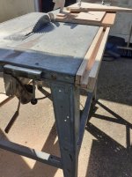
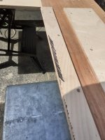
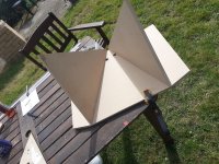
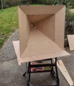
For about 3 years now I've been reading up on Tom D's synergy horns and collecting some drivers / getting my tablesaw sorted with a sledge guide / sledge etc (I found a post by me on here from June2018 saying I'm about to make a sledge 😀 )

I've finally made a test horn. I decided to try a 50x50 horn. Maybe later on I will build something more 90/60 but for now this project is to test the speakers and learn how to get the crossovers done well.

Drivers are BMS 4550 1" CD, with 2x Celestion TF0410MR mids.

I chose Fane Sovereign 10-250 bass drivers but it's been so long now that they have been discontinued 😱 .

For now I'm just concentrating on the tweet / mids....


I used 18mm MDF for testing with plans to use proper plywood when I do final builds.


I used Bwaslo's synergy calculator to get the panel sizes, however for my set up I had to work out a bit of extra length for the flare pieces (My saws blade tilts the opposite to Bills so I am removing material from the sizes given by the spreadsheet, whereas Bill is 'adding' material if that makes sense)

The spreadsheet requires you to line up the underside of your workpieces to the 'sacrificial' strip. The way I've chosen means I can line it up from the top which seems easier for me. I marked the sacrificial strip with a sharpie pen before running through to give me a sharp black edge to align to. Once the piece to be mitred is pushed to the edge just enough to hide the black edge I can clamp and be happy its accurate.

Here's a couple of pics of the sledge setup and the cabs. The screws in the flares have been removed and filled / sanded.

Attachments

  • sledge1.jpg
    sledge1.jpg
    178.9 KB · Views: 545
  • sharpie.jpg
    sharpie.jpg
    146 KB · Views: 539
  • started.jpg
    started.jpg
    146.7 KB · Views: 534
  • done.jpg
    done.jpg
    166 KB · Views: 551

Change password truncates password

Having been having trouble logging in to the site a couple of times, have had to reset password and login everytime.


It seems like change password silently truncates passwords while login does not. This leads to situations where if you change password to something too long(and thus gets truncated) you cannot login and have to reset the password. This goes unnoticed since changing password does not immediately require you to login with it.


It seems to happen in the 32-64 character range.

DC offset readings

Hi All,


I have a Rotel RA-971 mk2, when I measure it's DC offset on the speakers outputs I get 16.8mv for the left channel and 37mv on the right channel but on both the left and right channels my Fluke shows a "-" reading like the reading is in reverse polarity.
1. What is the reason for the reverse polarity reading?
2. How can I "balance" the DC offset readings between the left and right channels?

on the pcb there are only 2 bias adjustment pots


Thanks

Need help identifying: what diode is this?

Hi all

this diode has cracked in half in my project Eumig deck. It's not on a diagram, it is a part of a later upgrade. I need help identifying it, pictures are attached. Thank in advance.

Attachments

  • IMG_5223.jpg
    IMG_5223.jpg
    71.9 KB · Views: 137
  • IMG_5224.jpg
    IMG_5224.jpg
    94.9 KB · Views: 134
  • IMG_5226.jpg
    IMG_5226.jpg
    60.4 KB · Views: 135
  • IMG_5218.jpg
    IMG_5218.jpg
    131.4 KB · Views: 135
  • IMG_5219.jpg
    IMG_5219.jpg
    160.2 KB · Views: 140

What are my heatsinks good for?

Hi Members,

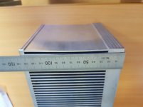
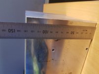
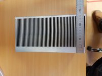
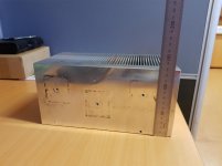
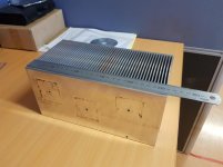
I was wanting to post this in "Solid State" but I thought it may be too general. I've salvaged 6 of the following heatsinks:

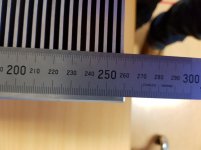
260(L)x130(H)x135(D)mm with a ~20mm base plate.

I was hoping to use them for an F5, Alpha Nirvana or something else entirely (fishing for suggestions 😀 class A or A/B). But I'm not sure how they translate to the recommended heatsink size. Both designs are recommending a larger attachment surface area heatsink, but they generally smaller fins and thinner base plates than what I've managed to salvage. Has anyone used something similar for a design like mentioned above?

I don't have a c/w rating unfortunately. Otherwise that may make things easier. I was also contemplating cutting them in roughly half, to turn them into 12 heatsinks...


Thanks for your time.

Attachments

  • 20200923_153617.jpg
    20200923_153617.jpg
    62.5 KB · Views: 189
  • 20200923_153732.jpg
    20200923_153732.jpg
    58.6 KB · Views: 182
  • 20200923_153644.jpg
    20200923_153644.jpg
    48.5 KB · Views: 183
  • 20200923_153728.jpg
    20200923_153728.jpg
    68.6 KB · Views: 181
  • 20200923_153639.jpg
    20200923_153639.jpg
    49.8 KB · Views: 193
  • 20200923_153623.jpg
    20200923_153623.jpg
    54.2 KB · Views: 101
  • 20200923_153629.jpg
    20200923_153629.jpg
    56.5 KB · Views: 103

Planning on trying to build Dyi speaker for the first time

Hey all, as the title suggests im currently in the planning phase of trying to build my own portable bluetooth speaker..
my question is, should i pick 4 Ohm speakers or 8...?

The AMP im planning on using is 2.1ch 2x50W+100W, rated for 12-24v operation.
I dont really want to have to build my own battery packs and Im Having a hard time finding a 24v rechargable battery pack.. so planning on using a 12-24v step up transformer aswell just so i can squeez more W out of my amp... (because im guessing the listed Wattage on the amp is at max operating voltage..?)

Im fairly new the while dyi audio scene so any tips regarding anything really is appreciated..!😀

Digitally controlled earth/gound/lift

Dear experts,

I am looking for solutions to digitally control the route of the pin1 of XLR/TRS combo inputs to either earth or signal ground or lift. PCB mounted miniature electromechanical relays such as Omron G6 are a solution. But are there valid alternative -cost and area effective- solutions?

Thinking of mosfet-transistors, mosfet-based analog switches such as CD4066 or newer equivalent components or optocouplers, I am actually not sure of the electrical requirements related to the pin1 to earth in line-level connections to be effective as earth to earth shield: maximum Ron, maximum current/voltage, earth noise isolation to control signal/gnd/vcc paths, etc

Would you suggest reference components to do that function?

Soldering Aluminum Wire - Help

I'm having no success at all soldering aluminum wire. Maybe someone can help.

The wire is 23 AWG and 32 AWG purchased from Magnepan to repair speaker panels. Included in the kit is a short piece of thick solder, hopefully for aluminum. It seems to have a high melting temperature.

I have read threads here and elsewhere about aluminum soldering, read papers, watched YouTube videos, etc. It seems that it is possible for some to solder it, but no success for me.

The wire is enamel coated so I remove all the insulation with 320 grit sandpaper. Seeing the removal is easy, as the wire changes from amber to a silvery color. I have used contact spray cleaner afterward to clean, or tried without a chemical clean. Getting the supplied solder to tin the soldering iron tip is very difficult, if not impossible. It mostly just beads up. Same for the wire, it will bead up but never wet the aluminum wire. There is flux inside the solder, rather foul smelling and dark.

wiki requests: images, nowiki

Seems that the [image] tag is broken. I don't want to risk broken links and images over time, so I wanted to upload all the JPGs directly to the wiki. But when I get them in there (upload new file wiki) and link to the image on the page in question, I get a "spinning ball." I believe I saw this bug reported elsewhere. As a "fix" I'm going to use imgur for these images, but like I said: that sort of thing can break over the years.

I also found keywords are getting automatically linked to existing wiki pages. Simply typing the words: introduction, wiki, or system, automatically links over to the corresponding wiki page. This makes my own links, that are actually relevant, get buried. There is a fix for the auto-linking, a tag called <nowiki></nowiki> but that doesn't work either. And it would be annoying to have to comb through my page removing these things anyhow.

thanks![/image]
Projects by fanatics, for fanatics
Get answers and advice for everyone wanting to learn the art of audio.
Join the Community
507,830
Members
7,889,986
Messages

Filter

Forum Statistics

Threads
406,334
Messages
7,889,986
Members
507,830
Latest member
LouisAtLarge