Need help, Sansui 5000a issues

Hello,

New here. My father has a Sansui 5000a and it's got some issues. It does have the original capacitors yet, nothing has really been upgraded/replaced. He has 2 issues. The first one is that the power transistor on the heat sink keeps blowing and putting the receiver into protect mode. He hasn't been able to figure it out yet, but said obviously something is overdriving it. Weird thing is that about 30 seconds before it blows, we get a strong smell of peanut butter.

The second is a little less destructive. After just turning it one, the left side speaker will always get static-y and then stop. Turn the balance to the left and pop it with a quick crank of the volume and it comes back on. Once it had been on for 15 minutes or so, this annoyance would stop and it would be fine. It's had this issue since I was a little boy back in the mid 70s. He always attributed it to static build-up in the receiver. Wondering if they could be related since (IMSMC) it seems to be the left side channel that's blowing the transistor.

regarding speaker protection against DC faults

Has anyone built Rod Elliott's speaker protection circuit ?

Here is the design:
Loudspeaker Protection and Muting

Has anyone used it with 15 Volts DC ? I am building this and had a couple of questions before I solder in the parts, since it makes it very difficult to correct PCBs once they are already populated.

I DO have his full build site which gives component values but since it is copyrighted, unfortunately, I cannot give that information out. But for anyone who has ALREADY bought his product and built them, the site is available.

What I want to know is, with 15V DC as the power supply, what should the values of C4 & R8 be to give a start up delay of AT LEAST 8 seconds. I was thinking about 100uF and 120k but I am not sure if those are correct.

Thanks

12HL7-triode SE Headphone Amp - I finally built something!

I finally (finally!) finished putting together my first self-designed headphone amp. I think it came out pretty well.

This amp is a pure junkbox project. The goal was to make a useful toy out of parts I've collected over the years. The idea was to NOT buy ANY parts, if at all possible. The amp's built in a discarded Heathkit W5M chassis a friend gave me something like 15 years ago. I also wanted to put to work things I've learned from folks here on diyAudio. Thanks to everyone who gave me advice and instruction along the way. (I know the "strain relief" on the AC cord is laughable. I promise I'll do better next time.)

It was pretty funny how many gremlins were tripping me up today. The first time I brought the amp up on the variac it blew its fuse. Turns out there was a faulty rectifier diode. Replaced that and brought the amp up again. This time the fuse held. Now the right channel tube's heater wasn't lighting up. A little jiggling of the pins in the socket and that problem went away. Weird. I checked for a cold solder joint, but all seemed fine. Oh well. Brought it up again. All seemed to be going well so I connected RCA cables to the inputs and gave it the Bzzzzt Test (touch the central pin in each RCA plug in turn, slowly turn up the volume, listen for the bzzzzt from each channel in turn). Hmmm, no sound from the right channel. Oh no... Continuity checked out OK. All resistances OK, including both OPTs. The output jack? Brought it out, disconnected it. Clip-leaded in a new jack and there it was. Would you believe a defective jack? Man, I'm snake-bit!

Finally, all was looking good. I took the amp off the variac, powered it directly from house AC. All good. Time to listen.

I connected the amp to my PC's soundcard, plugged in a pair of beater headphones, gave it a listen.

Four hours later and I'm still listening. This thing sounds really, really good to me. Clean and clear. Not "warm." Lots of impact. Drums go "thwack." Isaac Stern's violin is really nice. Not 'electronic' sounding at all. Bass has real body. I think it goes low enough to be enjoyable. (I was worried about that.) Overall the amp is 'livelier' sounding than my Objective 2 amp. I don't want to go down the rabbit hole of audiophool jargon blather, so I'll just post some pictures of my fuggly build and the schematic of the basic circuit.

In the schematic there's a B+ supply common to both channels, then the DC splits off into an RC filter for each channel of 560R and 330uF (R2 and C4). Later I hope to replace that RC filter with a simple voltage regulator member Elvee basically designed for me (thanks Elvee!). The idea is to have a couple of pretty 0D3 glow tubes standing on top of the chassis. I rigged it up with the passive supply to get it going.

I was worried about hum from AC heaters. I very carefully followed the suggestions in the "Heater Wiring - The Good the Bad and the Ugly" thread. I'm getting absolutely zero hum of any kind. (I'm so happy about that.) I also followed the suggestions for grounding layout in Merlin Blencouwe's Valve Wizard Grounding article. That worked perfectly too. (I'm elated about that.) I also referred to Merlin's "Designing High Fidelity Tube Preamps" book a lot, which was especially helpful for power supply stuff.

So it's a success. Gain is about 2X, I think. I haven't measured it yet, as I don't have my signal generator and scope fully accessible right now. I need to get to that.

Finally, I need to figure out whether I need damping resistors across the OPT secondaries for using the amp with 300 ohm headphones. The amp sounds excellent to me into my Fostex T50RP headphones (60 ohm impedance). It also sounds clean and clear into my Sennheiser HD650 headphones (300 ohms), but these supposedly 'dark-sounding' cans sound bright and a little bass-shy from this amp. I'm wondering if that's an artifact of putting a higher than optimal 300 ohm load on the nominal 50 ohm secondary. This weekend I'll have some time to clip in some different values of parallel resistors to see what sounds good to me.

But for now, I'm just happy this thing is working well. Thanks again to the diyAudio community.
--

Attachments

  • rongon_12HL7-triode_SET-headphone-amp_4July2018.png
    rongon_12HL7-triode_SET-headphone-amp_4July2018.png
    26 KB · Views: 1,003
  • IMG_20180704_180829235.jpg
    IMG_20180704_180829235.jpg
    500.6 KB · Views: 991
  • IMG_20180704_180741879.jpg
    IMG_20180704_180741879.jpg
    574.2 KB · Views: 873
  • IMG_20180704_180240405.jpg
    IMG_20180704_180240405.jpg
    679.9 KB · Views: 856
  • IMG_20180704_180249480.jpg
    IMG_20180704_180249480.jpg
    765.1 KB · Views: 940

Desktop Open Baffle Speaker System Project

After building and using a pair of on-wall mini bookshelf speakers, I decided to tear them down and build something with better bass and accuracy.

Building a set of mini on-wall speakers in wood was on the cards, but with one bad experience with a bookshelf speaker that turned out too shallow, I decided it was not worth the risk and effort at this point, maybe later. I also was set on using existing speakers instead of buying new ones - Fostex and so on, lets see what I can do.

Initial experiments consisted of using the existing Realistic 1011 or so woofers, and the unknown NS speakers that I purchased at the local electronics store for less than $6 a pair. Of course there will be the opportunity to spend later if I see the need to.

Initial testing with the TEA2025 PC speaker amplifier and a software equalizer revealed that the Realistic could output suffcient bass, but output volumes were very low. On the other hand the NS speakers sounded good enough, with a coil hacked from a crossover I bought many years ago, seemed adequate for the purpose: my only alternative now for desktop or in-room music is the mono Bluetooth speakers that I am now somewhat tired of.

A cardboard prototype showed some interesting results - the speakers were best about 60 cm from the wall, and lifting the speakers 30 cm above the desk improved the sound and made the distorted ringing sounds from the desktop disappear. So reflections are a factor after all!

Now all that remains is to build the baffles and fit the speakers, and find a sufficient coil for the crossovers.

Where to find isolating shoulder washers for panel adapters

Hi Folks,

I need a source for isolating shoulder/flang washers, the same as the ones attached to these RCA connectors

Yellow RCA/Phono Female F to F Panel Mount Adapter for Wall Plate Chassis Mount

To fit

--9.5mm connector diameter
--10.5mm rack hole diameter

Essentially, I am using a metal 1U rack mount to create a patch panel for Amp and Speaker testing and have a job lot of RCA and Speaker Binding through adapters. The Speakers ones didn't come with isolating washers and are the same size as the standard RCA ones.

Appreciate any links. Thank you

Class d recomendation for esl speaker

I’m about to make an upgrade from my Sure AA-AB32313 + Meanwell HLG-320-36A.
The speakers are Final sound 1000i, they do not dip to crazy low Ohms in the bass like most ESL speakers. A benign 4 Ohm load is/was promissed by Final sound.

The options I’m looking at are:

Hypes nCore board/diy
Ice edge board/diy

Crown DCi analog

Should I add other amps to the list?

The reason for upgrade is that I find the Sure AA-AB32313 + Meanwell HLG-320-36A combo is lacking in ”bass tightness”

Edit: Crown CTs has redicoulusly high damping factor From lowest hz to high hz. I’ll add it to my list allso.

Kr-950

Hi,I recently owned a Kenwood KR-950B Receivier, it`s actually not bad,it sounds very well with my speakers.(some older Noname speakers) The question I have is: there is an In- and Output(l&r) at the back writed on with "ADP". Has anyone an Idea for what it is? maybe a split after the preamp?

greetings
BastiB

Inexpensive Bluetooth amp for Radio conversion

Hello

I am of very limited ability in this area but always willing to have a go!

Looking for some advice on converting an old valve radio to a Bluetooth speaker

Plan is to leave all the old stuff there to keep the opportunity for a proper refurbishment later by someone more able

I have already bought a Sanwu tda 7492p Bluetooth amp , which works well enough for my needs except that the aux input, which seems to connect then disconnect,or the BT needs to be connected and paired but silent. Any thoughts?
I plan to use a laptop power supply,keeping all the HT all safely locked away

Next question is, if the BT is coming in stereo and I have only one speaker....how do I solve it and get both channels

Volume control, to make a gesture to authenticity it would be nice to use a pot for volume control (and power switching)

Dial lamps, it currently uses e10 filament bulbs, would warm white leds be an reasonable alternative

This is an experimental low budget project, based more on curiosity than need!

Any advice on this or a more suitable amp would be appreciated

Many 5hanks

SSR Hum

Ai do not remember having this issue before. But, seems I am on a roll.

Bought a nifty 40A SSR off the WEB. Hooked it up so USB controls the rest of the stereo. Serious hum in the transformers. Load dependent. Now before, I just had a very light load on a 10A SSR, but did not notice any hum.

So, swapped in the 10A. Still hum, but only when load over an amp.

Drug out the scope. I can just barely tell a switching glitch for the triac, but nothing I woudl think upset the transformers. Anyway, guess I am looking for a relay. I wanted the SSR as it pulls so little from the USB. Best relay I found is 70mA.

Anyone else have this?

Who Likes Gradient?

I left CES pondering a couple of things:

1) Dipoles sound really nice, particularly Vanderstien
2) Coaxes solve a lot of problems - the Kef LS50 was probably the best 'bang for the buck' that I heard at the whole show
3) tweeters in horns can't hold a candle to tweeters in waveguides

An obscure speaker from a manufacturer in Finland combined some of the best attributes of all these solutions, and I was surprised by how good it sounded. Particularly since it's a brand that seems often ignored.

I'm a bit curious if anyone else has evaluated them, particularly if they've heard John K, Linkwitz, or Vanderstien dipoles.

Besides sounding good, I was a bit surprised by how good the directivity is. With such a strangely arrayed set of drivers, I would expect to see ugly gaps and discontinuities in the polar response, but it's quite good!

GradientHelsinki_birch_sm2.jpg

810Helfig3.jpg

baa3d0adc88f6e6973cddb27c5b74fe0.jpg

1212KEF50fig4.jpg

Here's a couple of John Atkinson's measurements. The first is from the Gradient Helsinki, the second is from the Kef LS50 (which is also very good IMHO.)

May Kenwood KFC-HQ718 car speakers used in home hifi?

Reading some threads dealing with car speakers in home wifi, it seems that all in all this is not the best idea. However, I have a pair of Kenwood KFC-HQ718 speakers lying around and I want to check the possibility to use them for home hifi. Do you think it would be possible to get good results? any prefered design? or it will be a total waste of time?
Assuming my amp is able to drive 4 Ohms.

Thanks,
Aviv.

Currently available TO-264 insulators?

I am planning an amp build using a pair of TO-264 devices on the output of each channel, but am having trouble finding a matching thermal pad which is not electrically conductive. Datasheets for Bergquist suggest there should be Sil-Pads of appropriate size, but I cannot seem to find them in-stock at my usual suppliers (Arrow, Mouser). It looks like the DIY Audio Store's Keratherm pads will work, but the price is rather steep.

Does anyone know of thermal pads of sufficient size and affordable price? Is it possible to make these work with careful orientation?

Anyone know how to do a proper diode mod on a Sansui 5000 F1040 Board?

Just got a Sansui 5000. Heatsink very hot. Found out the bias in this thing was running at 450ma! Ouch. Lucky It dont have blown outputs. Was able to turn pot all the way own and get 26ma but something is obviously wrong with this driver board. Heard there is diodes that go bad and there is a mod but cant seem to find how to actually do the mod. Anyone familiar with this mod?

FS: enclosures, punches, books, more

FS: enclosures, punches, crimping tools, books, LPs, more

NEW sealed Moduline Electronic Instrument Enclosure, 17" x 14" x 5" Blue | eBay
GREENLEE 9/16" PUNCH, in excellent condition
GREENLEE 1-1/4" PUNCH, in excellent condition 783310040088 | eBay
GREENLEE 1-15/16" PUNCH, in very good condition 783310040088 | eBay
GREENLEE ROUND PUNCH, 1.334" diameter, in very good condition 783310040088 | eBay
GREENLEE 1" SQUARE PUNCH, in excellent condition | eBay
MOLEX hand crimping tool, model HTR 2445A, in excellent working condition | eBay
VACO crimping tool -- https://www.ebay.com/itm/293604162383
Many jazz/rock/classical CDs -- https://www.ebay.com/itm/293714995043

Electronics and audio related books, reel to reel prerecorded classical/jazz tapes, 300 mono RCA LPs, etc.
https://www.ebay.com/sch/marion8pvg/m.html?_nkw=&_armrs=1&_ipg=&_from=

Following items for local pickup in Madison, WI area, due to weight. More info/photos on request.

Cambridge SoundWorks, pair of subwoofers & small satellites, good for video.
The two subwoofers can be used separately however you wish. $100.
Hallicrafters S-85 shortwave communications receiver, looks very good, works. $95.
Nikon stereo inspection microscope w/heavy stand $150. Very good for SMT work.
The Advent receiver $100 (with Holman phono circuit) 15W/ch amplifier, good sound.
More info: https://www.hifiengine.com/manual_library/advent/300.shtml
Rotel receiver
Yamaha receiver
Infinity speakers, smaller cabinets
Proton 100 FM/AM radios, have two, $50 each. World's only biamplified table radio (and the heaviest, too).
Akai GX-280D-SS reel to reel tape deck $395. Very good condition, with original take up reel.
More info: https://www.hifiengine.com/manual_library/akai/gx-280d-ss.shtml

Mark K's ER18 DXT tweeter adjustment addendum.

A couple of days ago I was browsing the net for details or mods to the Seas Idunn design when I came across a comprehensive addendum to a Seas 27 TBCD/GB-DXT tweeter equipped speaker which I am convinced was the Mark K design*(but might not have been!) . It was a very comprehensive set of plots showing the subtle changes to the level and crossover frequency by changing 2x resistors....I think there were at least 4x variations. I thought I had bookmarked this but it seems I didn't and after spending hours looking for it today I have given up.
Does anyone know or recognise the web page I describe and be so very kind to direct me to it? Very much obliged and thanks for reading this...🙂
PS* the web pages may have been on the "Audio Excite" "Prestigious Two-Monitor DXT" as I'm pretty sure the resistors were R1 and R2 that were changed. I've looked everywhere on this site though.

Well I kept on looking and now found the page, it is here: www.audioexcite.com >> Blog Archive >> Prestigious Two – Monitor DXT Tweeter Level Option Update!

Sorry for the question but hopefully someone will find this interesting too.

Les

MTX Audio TA81001 Thunder output issues

Amp came in for repair.

Kind-a works but the output is heavily distorted and doesn't even look like a sinewave. No power light on, no protect (LEDs work, tested them outside of the board).

It's the big brother of MTX 7801. I've checked your guide Perry and followed everything through it.

Optocouplers, N5532, rail voltage, supply voltages are all fine. Oscillation is as it should be according to the Perry's manual. I've re-soldered the inductors just to be sure. I've used jumpers to preamp bypass.


From the pictures:

The clean sinewave is taken at the jumpers.
The distorted one is at the output of the amplifier.
It's the same if i re-connect the pre-amp section.

I've noticed that the output filter caps get warm. They are nichicon 63v 470uf, doesn't seem they have been changed but in Perry's guide the ones over there are Panasonic, but the voltage and capacitance can't be seen.
I took out 2 caps and measured them - they read just fine 501uf, ESR=0.1ohm (leads resistance not taken out).

What else to look for ?

Attachments

  • 1.jpg
    1.jpg
    846.6 KB · Views: 223
  • 2.jpg
    2.jpg
    273.6 KB · Views: 146
  • 3.jpg
    3.jpg
    305.1 KB · Views: 150
  • 4.jpg
    4.jpg
    803.9 KB · Views: 150
  • 5.jpg
    5.jpg
    634.1 KB · Views: 155
  • 6.jpg
    6.jpg
    418.1 KB · Views: 105

Primare SPA21 problems

Hello.
Amplifier processor PRIMARE SPA21.
Only one anolog input working.
Sometimes not respond to remote control.
The display is very low contrast.
No video output.
Its work only one analog input,2 channes works fine.
No video output,no possible to change the settings.

Can you help me with repairing ?
If possible to make factory reset on this amplifier.
Regards
SM

PRIMARE SPA21 SURROUND PROCESSING AMPLIFIER SM Service Manual download, schematics, eeprom, repair info for electronics experts

Harman HD980 (HD-980) - getting most ultimate Sound in the Economy Class ?

I have heard several times from different users that this is an exceptionally good sounding CD player. I haven't heard until now.

From the internal view (SMPS-PCB instead 50Hz resp. 60 Hz transformer, DVD/MP-3 PCB and Laser etc.) I wouldn't expect such listening results.

What is here very special in opposite to usual DVD concepts ?
Service manual is here:
HARMAN-KARDON HD980-230 REV1 CD PLAYER Service Manual download, schematics, eeprom, repair info for electronics experts

Thanks for an advice.

The HD-970 has already been discussed here - go to
https://www.diyaudio.com/forums/dig...mon-kardon-hd-970-modded-world-beater-12.html
but this is an other version with other PCB's.

Attachments

  • harman-kardon_hd-980-interior.jpg
    harman-kardon_hd-980-interior.jpg
    31.6 KB · Views: 489
  • 4c27337ba02967c9a9f383011560aee9.jpg
    4c27337ba02967c9a9f383011560aee9.jpg
    34.8 KB · Views: 284
  • 7bbe6094c0afcb0d5a8e51137ccdf8eb.jpg
    7bbe6094c0afcb0d5a8e51137ccdf8eb.jpg
    53 KB · Views: 312
  • 7c8c0fdab230b2a81f017063ca221c70.jpg
    7c8c0fdab230b2a81f017063ca221c70.jpg
    126.4 KB · Views: 570
  • 52e6e92b653e7deaa312e5fa8f0a882d.jpg
    52e6e92b653e7deaa312e5fa8f0a882d.jpg
    51.5 KB · Views: 412

FS: various pro audio equipment, void, master audio, nexo copy, 18sound, bms

For sale:

4x Ohm TRS-115 mk1 450,- per pair 800,- for all four
2x EAW JF260 1000,- for the pair
4x Nexo Alpha S2 copy (identical from the inside, same tuning etc, 18mm birch ply etc.), loaded with B&C 18PZ46 drivers. 3200,- for all four.
2x Bandpass sub like Nexo LS400 (empty) 250,- for the pair
2x 18Sound 12NLW9300 (good condition) 400,- for both
1x BMS 4548-16 OEM 60,-
1x L'acoustics HP BC122 (freshly reconed) 150,-
2x Master Audio SM4000 amp (2x3000 Watt @2 Ohm stable!) 725,- per piece, 1400,- for both
1x Void Infinite 7v2 950,-

Price is in euros and can do a discount when more items are bought.
Feel free to pm for more info or pictures (located in the Netherlands).
Shipping is certainly possible for the smaller items, I do not have any experience with pallet shipping, but I am sure we can work something out if it is needed.

tda1305 / micromega st3 noob question

Hi all,

got micromega st3 salvaged by previous user - it had overheated trafos on DAC board with fried 1305 dac chips and output op-amps. Got dac chips replaced with 5$/pc from aliexpress, restored all op-amps, power etc. Got nice sound, clean output.

BUT - there's a strange option of double speed play - dunno why it is in CD player, but still. Once pushing x2 button, it plays on double speed just fine, but linear output distorted with pops and clicks and loud noisy sounds like... heavily scratched vinyl. Well, at normal speed it plays just fine, but on x2 - pops and clicks, however the original sound is also there.

Is it possible that I got counterfeit 1305 which are re-labelled something pin compatible but without x2? or something wrong with opamps?

no pops and clicks with spdif output to external dac on any speed.

Amp recommendation

Long time audiophile here, but new to the group. Great forum!

I am in consideration of a 21" Eminence subwoofer (https://www.parts-express.com/pedocs/specs/290-5662--eminence-nsw6021-6-spec-sheet.pdf) to augment my 4 other Dynaudio subs in a large basement setup (they are great, just not big enough). The speaker is 6 ohms and most are using large (at least on paper) Behringer or Crown type pro amps listed at 2000-3000watts, which is likely more like 800-1300watts rms. As a higher end HT guy, putting pro amps in my room seems a bit like sacrilege. I'm not really sure why to be honest, so I'm opening my horizons.

I don't know what amps are out there. I've been looking at Crowns mainly just because I know the name and they are USA made. If realistic, I'd like to spend around $500 - lower the better and I don't mind buying used. It seems like there are a lot of pro audio amps around and each year varies a bit w.r.t. functionality. I've been having trouble finding one that meets my exact needs:

  • 1000-2000watts rated power - higher the better, a bridged 2 channel is fine
  • Supports 5-6 ohm load (sub is rated at 6 ohm, but it can dip a bit lower)
  • Under $500 (used street price is ok)
  • 12v Remote trigger capability (don't really want to use a smart power strip)
  • 15-17hz high pass capability (to protect low end xmax/over-excursion its recommended for the Eminence sub - the ported enclosure is tuned for 20hz. I will use my avr to low pass it)

-The Crown xls 802 has a 15hz high pass but alas it is not stable below 8ohm when bridged, nor does it have a remote turn on. The newer Crowns only have a 30hz high pass which is too high.
-The new Berhringers have good power and nice DAC's in them, but require a fan mod and have no 12v trigger
-Some of the QSC like the DCA3422 have the power and remote turn on capability but their high pass filter is only 30hz which is way too high.

I figure some of you pro audio guys out there know these amps backwards and forwards and can suggest another amp. I'm sure I'm missing some older models in my searching that may have the features I need. Its funny when I think about car audio sub amps, MANY of them have all of these features, but its a bit of a needle in a haystack exercise to get it in the home. I know I can get a smart outlet for the trigger and I know I can get a minidsp HD for the xover, but these are essentially Band-Aids - I'd love to have an amp that just does all that for me. Thanks.

help needed with exponential horn

I am trying to build a folded exponential horn with a collapsible throat, for a mechanical phonograph project, which will also be used with a tiny fullrange unit.

Would a throat lengthened/shortened about 4.5cm have any audible difference in a 130cm horn's sound quality? 😕

The horn will have a throat of 16mm, a mouth of 75cm in diameter, thus reaching down to 228.8hz...

Attachments

  • 20201020_143350.jpg
    20201020_143350.jpg
    519.2 KB · Views: 118

Drivers stopped working halfinator

I recently completed a halfinator build.

I wanted to add Bluetooth and a preamp in order to get the most out of the speaker. I wired these up today and when I tested the Bluetooth and preamp only the tweeters were producing any sound. Went back to original set up, still only sound outbid the tweeters. Swapped amp (tpa3116 mono) with a new one in case is wrecked the amp, still same.problem.

I didn't hear any worrying noises to indicate I damaged the hp10 drivers.

My amp has a startup plop, this has also been replaced by a click from the tweeter.

Anyone have any ideas? I really hope I've not ruined the hp10's but don't see how I could have.

Pre amp: XH A901 NE5532 Tone Board preamp Pre amp With treble bass volume adjustment pre amplifier Tone Controller For amplifier Board|Operational Amplifier Chips| - AliExpress

Bluetooth: Bluetooth 4.2 Receiver Board CSR64215 Bluetooth Module Lossless APTX Wireless Bluetooth Audio Receiver Board|Integrated Circuits| - AliExpress

Amp: TPA3116D2 Mono Amplifier Board 100W DC 12V 26V High Power Audio Digital AMP Module Sound Speaker Board Volume Control|module dc|module powermodule board hot - AliExpress

SAE Mark 1b noise in EQ circuit in one channel only

The noise stops when the line/tape button is pressed in (that button changes the EQ application from the line stage, to applying it to the tape buffer circuit). The EQ circuit is entirely passive, with a few polystyrene caps, a few (recently replaced) electrolytics and a few film caps. Also, the 960hz slider does not boost in the same channel that has the noise, but it does cut. Any ideas? It must be a passive component that is introducing the noise, I assumed it was broken graphite in the 960hz slider acting as an antenna.

help! STR-DA777ES

I am having a strange problem with this amp,
i use this amp in 2ch mostly,but have speakers hooked up for 5.1 for movies,
very randomly (can be a hour or 8 hours use ,in fact not at all for days) in 2ch mode it will produce a loud static hiss though all speakers ,music is not heard at the same time i think, it lasts for about 5 sec and then silent ,i can turn the hiss(crackle) down if i get to it fast enough with volume ,
once silent it will not pick up any signal ,once i turn it off and back on its normal till next random time to do this

if any one has seen this before or repaired this problem before id love to ear from you
mike

ps , this is my first post so hello to all ,😱

Devices with high Early Voltage

A nice high Early Voltage is important in certain types of topology but this spec is hardly ever given in data sheets (although it can be estimated from family of characteristic curves). My question is does anyone have data as to which BJT's perform best in this respect? Especially complementary pairs. I would guess that video output transistors should be pretty good but would welcome further information from anyone who has looked into this.

tseii biasing question

Ive been running my tseii for a while now and all has been great. I decided today to check/adjust my bias since it had been a while. I am seeing some odd behavior while trying to set bias on the right channel. Im running just under 400 b+ and b- is showing around -200. I am trying to set current at 75ma. The left channel is nice and stable but the right channel continues to drift after i make an adjustment.

I checked the bias voltage at the 300b and it is around -66v and is stable even when the tube current is fluctuating. My first thought was the tube was the issue but I swapped tubes and the issue stayed on the same channel.

What should i be looking at to solve this issue? Thanks for any help

Triode Dick's KT88 PP Amp.

Hello everyone!

First of all, sorry my bad English.
I'm typing here in Finland...winters coming...

Anyway, I'm building Triode Dick's KT88 PP Amp in stereo.

i'd like to know what are the resistors R17 and R18 in The chema?
Are they 1R and what wattage?

Thank's a lot, if anyone can help me littlebit!

Juha from Finland.

http://members.home.nl/triode.dick/Bill/schema_versterker.GIF

Basement Soundsystem - Guidance Needed

In a month I'm moving into a new house and I'm working on designing a music-focused sound system to go in the basement for a DJ/dance party setup. I've put together a two-way top/main that I'm really happy with thus far (passive-crossed PRV 8MR-500NDYv2 with a B&C DE250 on the ME20 horn), but I'm struggling with what to do for the bass/sub area.

Specs: Room is approx. 14 x 24, maybe 8-9' ceilings. Drywall + carpet.
Planning for two mains and two subs in opposite corners - mains mounted on ceiling, subs on the floor. All enclosures must be DIY. Crazy SPL not required but should have plenty of headroom as the space will (hopefully) be full of bodies from time to time. Pro amps & EQ will be used - subs will probably run parallel off a single channel. Music will primarily be house, disco, techno, funk & soul. Hoping to build at least one sub in advance.

Now questions:

1) What size subwoofer/bass cabinet(s) is recommended for this space? I had initially planned on 2x18's but after testing one main in a similarly-sized basement room with a single low-power 8" sub driver, I'm wondering if 18's are overkill. Certainly a smaller driver would save some floor space. I don't need ridiculous low bass (my neighbors foundation is merely 4' away) but would like plenty of 'kick' to the drums; I suppose that means transient response is as or more important than depth?
2) Would a simple reflex cabinet suffice? Simplicity of construction is a must, and smaller is better (4-6 cu.ft. is doable, as long as it's tall and shallow). I understand the trade-off from sealed to vented, but I don't know if that will matter for my application?
3) I'd prefer to stay under $100 per driver. I had initially pegged the Dayton Audio PA 18" as I won't need crazy power or XMAX, but maybe I've overlooked something? Or, if going with smaller diameters, what would you recommend?

Thanks all.

Ripole Dimensions ( Help Needed )

I have been Sitting on Purchased Speaker Driver Units to start a Three Way
Open Baffle Build for a while, and this is now looking to be my Winter Project.

I have selected Two Way box speakers to use while the Quads are out of use and the OB's take up their position.

I would like to try out a Home Built Ripole with the Quads before I dismantle the Stacked 57's, and then try out the Ripole as the first OB Sub Woofer to work with the rest of the OB Array .

I have an itch to Scratch and would like to produce a
Ripole Sub using 4 x (very used) Eminence Beta 15's, where there will be
2 x Beta's mounted in a Framing, and have a 2 x Driver Ripole produced for each Channel, to have the experience of the Ripole as a Sub Woofer Design.

I have been extracting various information supplied on here to produce a Ripole using 15 Inch Drivers.

To attempt to get the Framing Dimensions as accurate as possible to match my drivers.
I have used an information shown in a Post where the Beta's Xmax is less than 10mm at 4mm,
the Front Chamber Opening is to be calculated at 0.25 x 823.7 Sd .
The Rear Opening is to be calculated at 0.5-1 x 823.7 Sd.

I have never built a Speaker before of any type, and my Maths are not quite working out, as I don't seem to be creating any Width to a Chamber, that is close to some of the Build Plans I have reviewed ? .

I can forget this and use a Plan for a 15" Driver I have downloaded from this Forum, that has a Side Panel Dimension of 412.74mm (H) and 419.1mm (W).
The Font Chamber Opening is a 152.4mm (W),
the Rear Chamber Opening is a 76.2mm (W).

If there is a benefit from using the Driver Specification to produce the dimensions ?, then this is how I would like to proceed, and would be greatful if I can be given a Pointer to Side Panel Dimension and the Chambers Width Spacing.

The Beta's are 384.8mm in Overall Diameter and has a Depth of 153.7mm, my Side Panel dimension on Paper to accommodate this Drivers dimension is 435mm x 435mm, which was simply produced by adding an extra 25mm to the Perimeter on each plane.

Thanks in advance for any advice offered.

4U / 500mm Dissipante Chassis

Jason & Co.:

Can you provide some clarity around what is included in the new 4U / 500mm Dissipante chassis mentioned in the diyAudio store? The "Ultimate 4U 500mm Chassis" thread has discussed a lot of options (UMS drilling, base plate, custom rear panel, etc.) but it's unclear what is actually included in the Store's offering.

Also, is this chassis even available? When do you expect shipments to start?

Thank you,
Scott

Odd tube amp transformer

Many years ago, maybe 10-15 years, I purchased from either Korea, Taiwan or Singapore a pair of transformers. I could even have bought them from German company Welter Electronics, but the product code doesn't add up.

I have already forgotten what I intended to use them for, but could have been intended for 2A3-SE or EL156-SE, but ... I haven't the slightest clue.

Here comes the mystery. I simplyu measured the resistance and the yellow wires indicates 0 - 4 - 8 - 16 Ohm secondary/output.
But primary/input makes me confused. The two red and the two green wires have a resistive connection and my guess is the following:
Between the green connectors I measure approx. 190 Ohm/9.16H - that could be a 3.5k Ra connection.
Between the two red wires I measure approx 170 Ohm/7.57H - could be a 2.5k Ra connection.
Or 5k/3.5k ...??

Transformer is (when looking at the pic) H 3,5" x W 2 3/4" x D 2,5". Iron core is approx 1 1/4" x 1/2".

What do you experts say, what did I grant myself many years ago? maybe someone recognize it ...

And no, it is not a mains transformer; I've got two of them.

Attached images, showing picture of the transformer and a graphic of the primary and secondary.

Attachments

  • trafo1.jpg
    trafo1.jpg
    102.6 KB · Views: 87
  • trafo.jpg
    trafo.jpg
    76.1 KB · Views: 87

Advise on hum on input wire of phono stage

Regards.

I own a DACT CT-100 phono preamp module card. Its installed inside a diy preamp metal cased along with a DACT ct-101 line stage module, a DACT CT-2 10k attenuator and Dact CT-102 power supply. Sort of a kit.

Currenty my turntable has a Sumiko SHo moving coil cartridge, 1.8mV wired with 1 meter of Discovery cable from cartridge pins to male RCA for connection at the phone stage case RCA’s.

I believe the hum issues are related to CT-100 installation or operation, not the tonearm wires or cartridge.

To identify cause I have done the following:

I.
The hum is on both channels when I select the phono for playback, even if the turntable motor is off.

With unit powered, cartridge output cables disconnected from CT100 input RCA’s I get white noise if volume is turned up. The white noise goes down with volume and its much lower than music playback. All OK.

If I open the case and put my finger near, or touch, the center wire connection inside the case input RCA (where RCA center pin is soldered to same wire as connected to CT100 IN1) I get a hum that varies with the distance between my finger and the solder point. The wire connecting the RCA to the board is shielded, and shielding is soldered together with cable return wire to CT100 board connection point.

The same happens with the other channel IN2.

I this hum normal?

II.
The RCA connector installed to chasis IN1 and IN2 is a WBT Nextgen (which has an insulated plastic body fixed from the outside by a metal collar acting as a nut. Said collar nut does not touch any metal at all as it is screwed to the RCA plastic body).

If I touch the RCA metal collar outside the case, I get the same hum as I described when my finger is near the female RCA solder point inside the case. I believe it is due to the metal collar acting as "antena" for my finger near the same center pin of female RCA for IN1 and IN2.

Again… I this hum normal?


III.
When I connect the cables coming from the cartridge to RCA IN1 and RCA IN2 and the tonearm ground cable to the case uninsulated ground post ( as stated to do in the phono card installation instructions), I get hum. Less than describe before but hum.

The rest of the CT100 installation includes a ground cable connected to the same CT100 ground lug as the case ground post for tonearm. That cable is fixed to the same point in the case as the ground wire connected to the CT-101 line stage pre board.

Any advise on how to deal with this?

Thanks to all.

ideas for a new build !

My friend just built a Home theatre and has asked me to build speakers for him.

Some high level project goals:

- The budget for the L + R is around $2k.

- He wants it to be able to play loud, with lots of deeper Bass (40-70Hz),

- but also sound "high end" at lower volumes

- The cabinets cannot exceed 10" baffle by 60" tall (maybe 16" deep at most)

- He is open to Subwoofer augmentation of the lower LF

- Primary use, Home theatre and dance parties , secondary use, Audiophile listening...


Thinking of building it around four Dayton RSS-225-8's... still deciding on mods and tweets


Thoughts...

Meridian 596 refresh

Has anyone recaped/modded one of these units. As good as it is(dispute 20 year old components), is there points(no major changes) to be improved. I'm thinking to replace the Dig out with a 75 ohm BNC, and RCA analog outs. The cooling fan is needing replacement. Since I only use it for CD playback both analog and Dig, and the unit works without the video out connected to the PS, any benefits leaving it disconnected? I ask for those with experience because I don't want to repeatedly disassemble the unit. Experience talking here.....

Open baffle treble questions

Hi.I cut these open baffle speakers enclosures and my friend assembled them.He says he gets lots of bass but not happy with treble.I advised him to add a Tweeter with a simple serial capacitor but he does not accept it.He told He want to get better treble by playing/changing crossover.Any advise about crossovers to improve treble?

Attachments

  • IMG-20201013-WA0015.jpg
    IMG-20201013-WA0015.jpg
    95.2 KB · Views: 235
  • IMG-20201013-WA0013.jpg
    IMG-20201013-WA0013.jpg
    82.7 KB · Views: 238
  • IMG-20201014-WA0002.jpg
    IMG-20201014-WA0002.jpg
    94.1 KB · Views: 230

Ampeg B500DR bass head solid state

First off thanks for any help you can offer. I have a Ampeg B500DR bass amp that won't get put out any bass guitar sound. When I turn up the volume the fuzz gets louder but no signal output. There is a relay I was tapping on and after a few taps I resistor in the power section fried. I attached the block diagram but could really use the schematics if anyone out there has them.

Attachments

  • B500DR.jpg
    B500DR.jpg
    41.1 KB · Views: 190

3KVA toroidal line isolation trans $125

Pic 1

Pic 2

Pic 3

$125 **

Suppress electrical noise in sensitive devices.
Very effective in eliminating line noise.
Improvement in sound quality.
Very effective, especially in congested urban locations.
Provide galvanic isolation to protect against electric shock from the mains.

Manufactured by Electromagnetic Industries Model 541-1-1
Rating is 3KVA 60Hz 120V primary/secondary
80 deg C rise
Insulation class F (which is 180 deg C)
Leakage 10 microamps max.
Weight approx 66 lbs
Approx 16" diameter and 3.5" height

I have more than one available. Appear NOS.

**Prefer local pickup in Moorpark, CA. Will ship within CONUS (Fedex ground home delivery estimated to be $70 to $150). PayPal OK. No returns. Reasonable offers considered.

Advice needed on Nichicon capacitors

I'm continuing with my projects, which include doing some much-needed cap replacement on some vintage amps, receivers, etc. I've decided on Nichicon because they have a huge variety of caps and I'm having better luck finding the sizes, values, and mechanical specs (mounting points and exterior dimensions).

HOWEVER...

There seems to be a big bunch of info about which Nichicon grades are appropriate for what circuits. Everything I've seen in both Nichicon data sheets as well as stuff I've read here tells me I should be looking for KZ, FG, and KA in the audio path, and KG/KS for the power supply and supporting circuits.

I'm getting ready to put my order in, and I've been discussing it with a product advisor at one of the biggest parts houses. Today I get an email from him telling me I should be looking at ES for the signal path, and FG and KZ for the power.

That doesn't make sense to me. I haven't seen an FG above 4700uF, and definitely not in KZ, where the highest value appears to be 1000uF. So how can I build out the power supply with those grades? And I've never once seen anyone here recommend using FG or KZ for power - only signal. Did the guy get his recommendations backwards?

What is the most appropriate cap for power filters, as well as the supporting regulation circuitry? What about the stuff like audio paths, especially when you get into preamps?

TIA

In short - what should I use where, and what should I avoid using in particular situations?

Ground Zero GZPA 1.8K HC

Hello, received this amp, blown output.
Removed all fets, installed new drivers, checked everything, seems ok.
Gate Signal on low side also ok.
Mounted new fets, it blows some fets directly.
Removed all fets again, new drivers, and checked with two fets, bank by bank. One side ok, if i mounted the fets on the other side, directly all drivers blown again.
Removed fets and drive board again.


Checked the pins on the mainboard for the drive board. I have a saw tooth on pin 1, 10, and the 3.rd row, Pin 2 and 29.
I dont know what happened here

Luxman R-800 no FM (or very very weak)

Hello,

I'm having some issues with a luxman R-800. When I got it the symptoms were : no fm reception and popping/crackle noises when fm selected accompanied by wild movements of the two meters (centre and signal strength). The auxiliary inputs work fine so it's not the preamp. I replaced two transistors in the front end portion (q102 and 103) with 2n5770 as q103 was an infamous "flying saucer" and actually had a gain of 1 when tested. Now I still haven't got any reception (that is unless I directly connect an fm signal generator to the antenna with its output at max and I only just get enough deflection on the signal strength meter to actually notice it, and with fm muting on it stays dead silent) and the popping sounds are still there although a lot less perceptible. I don't really know where to start although I can already say that the +12v rail is present even if rather at 13.2v.


Thanks in advance for your help

DIGI-125 Kit Amplifier Module

Hello All, Found this whilst out trawling.

Australian, Graham Dicker designed, Aust $39.00, DIGI-125 amp module kit, ( http://www.bettanet.net.au/gtd/kits.html ).
7 transistors, 2 diodes, 8 resistors, 3 capacitors, no adjustments, +\- 38 Vdc supplies, 125w/4ohm, (200w/2ohm modification).
0.06% at rated power, 0.01% 10Wrms, 100Khz power bandwidth, DampingFactor - 90 wrt 8 ohms.
Looks to me like an easy, cheap, quick way to build acceptable surround/triamp setups etc, economically.
I am keen to hear experiences, and sonic critiques, and mods -
27,000 sold can't be all wrong maybe.?

Regards, Eric.

Dynamic load for power supply testing

I've been experimenting with DMOS since SY got me started with "His Majesty's Noise" RIAA preamplifier.

It seemed to me that one could self-bias a DMOS and use it as a current sink. Sweeping from 10Hz to 10MHz and measuring group delay, you can quickly determine whether the power supply/regulator is stable.

The IXYS IXTU02N50D has Ciss of 120pF. The gain plot uses IXTU02N50D, not the DN2540 shown which is 200pF.

Attachments

  • DMOS_ActiveLoad.png
    DMOS_ActiveLoad.png
    21.7 KB · Views: 167
  • DMOS_ActiveLoad_LTSpice_Schematic.png
    DMOS_ActiveLoad_LTSpice_Schematic.png
    18.7 KB · Views: 178
  • DMOS_ActiveLoad_LTSpice_PLOT.png
    DMOS_ActiveLoad_LTSpice_PLOT.png
    24.9 KB · Views: 178
  • DMOS_Sink_Bode100.png
    DMOS_Sink_Bode100.png
    46.7 KB · Views: 163

Need advice - WinISD Transfer Function

Hi guys

I am trying to design a small Sub, nothing big and am still learning how to use and interpret WinISD.

I have an existing MDF cube I would like to use, 27cmx27x27cm inner measurements (~19.6 liter) and played with a couple of drivers . I do understand the meaning of F3 but the curves (see attached) look quite a bit different between vented and closed and I don't exactly know how to interpret them. To me the orange one seems to be the best, but I might be wrong.

Any help is appreciated.

Kind regards
Phil

Attachments

  • Sub Design Samuel.PNG
    Sub Design Samuel.PNG
    66.7 KB · Views: 129

fake epcos snap-in capacitors?

So recently i purchased some EPCOS capacitors online from a local store which is not an authorized distributor for TDK, but seems to have lots of different known brand items in the store and is well reviewed. When the capacitors arrived, i noticed they deviated a bit from the datasheet. they don't have the "PET" marking on the sleeve as described in the datasheet, and the pins are attached to the capacitors in a different position. I'm attaching pictures of the capacitors in case any of you are familiar with the brand and have purchased confirmed originals and know if they look like these or not. At the moment i don't have a way to measure them, and when i contacted TDK, they basically told me to look at the datasheet, which i had mentioned to them i already had.
Thank you!

Attachments

  • 2.jpg
    2.jpg
    646.3 KB · Views: 285
  • 3.jpg
    3.jpg
    735.3 KB · Views: 280
  • 4-2.JPG
    4-2.JPG
    145.2 KB · Views: 280

Copper corrosion protection

I did a lot of amateur research (amateur although strictly confined to industrial experts’ writings, not mumbo jumbo) into PC watercooling to try to figure out how to make a good coolant, since coolant makers offer voodoo products with ingredients that aren’t good (like dyes, fluorescents, and opacifiers) as well as trade secrecy. I discovered, for instance, that an industrial consultant for said glycols (whether ethylene or propylene) cannot be less than 20% of a water solution or they will develop harmful biological growth. The solution will become quite harmful to the metals it’s supposed to protect.

That contradicted an absolutely huge amount of amateur advice about “splashing” glycols in mixtures and using small percentages, like 5–10%. Apparently, too little glycol is worse than not adding it at all. That’s the opposite of the amateurs’ advice. They claimed that even this smaller amount of glycol will function as a biocide and/or increase lubrication and/or improve corrosion resistance. And, some commercial small business watercooling coolants claim to use less than 20% glycol, so they are apparently a bad choice for your equipment.

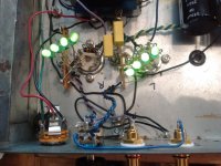
One of the things that I focused on a lot was on stopping the corrosion of copper. Since copper is commonly used in speaker parts (amp internals, wiring/connectors, etc.) I felt that I would share some of what I learned with the community here. Specifically, it’s about what can be done to treat the copper to reduce its penchant for corrosion due to air exposure. The short answer seems to be a dip in a tolytriazole solution (tolytriazole dissolved in ethanol).

However, other solutions may be even better. Some may be considered ‘good enough’ depending on the criteria. IBM uses BTA (benzotriazole) for its computer watercooling systems, probably because BTA is much more water-soluble than tolyltriazole. However, it may be more optimal to dip the copper parts in an ethanol solution of tolylriazole before putting it into a loop containing BTA water.

There was an interesting study involving the preservation of copper artifacts. Only one of the tested solutions stopped corrosion completely and it wasn’t one of the solutions using distilled water as the solvent:

BTA (benzotriazole) + AMT (1,3,4-thiadiazole) in ethanol

The ratio was .1M BTA + .01M AMT. Surprisingly, such a small amount of AMT did make a difference.

The same combination in distilled water had comparatively good performance (versus the other chemicals and mixes beyond the one cited above) but corrosion still happened. I believe that the artifacts were kept in the liquid. I do not know if the AMT, for instance, would make a difference for parts that are removed from the liquid. I also don't know how finger oils/contaminants will interact.

I also do not think that the study included tolyltriazole. Here is a link to the study: A Corrosion Inhibitor Test for Copper-Based Artifacts on JSTOR

Tolyltriazole is apparently commonly used in industry, not only for some automotive corrosion resistance (like in some antifreeze mixtures) but also to protect copper parts from tarnishing from air exposure and such. As far as I know it is common for copper parts to be dipped in a solution of this.

advantage (versus benzotriazole) : thinner yet more effective coating (more hydrophobic) than benzotriazole

disadvantage: poor water solubility

There is also a longer carbon chain triazole. That is napthotriazole (related to napthalene — moth balls). It was briefly used in the laundry business. One piece of data I remember reading gave it better protective qualities than even tolyltriazole but I did not find any chemical companies that offer it. It would certainly not be soluble in water but if used with the dip method (ethanol?) might be better than tolyltriazole to coat copper to protect it from air exposure.

Copper oxides have very low thermal conductivity when compared with the copper metal, so a thin protective layer is better for PC heatsinks and watercooling waterblock channels than oxidized metal. I assume the electrical conductivity is also much lower.

(Despite the reduction in thermal conductivity and the problem of unsightly corrosion—that gets worse—many in the PC water-cooling community recommend using only distilled water with a silver coil as a biocide. That does not seem to be good advice due to the solution not protecting from galvanic corrosion, silver exacerbating it due to the presence of nickel in particular, there being no pH buffer, etc.)

Another mistaken bit of advice from amateurs (propped up by some small businesses) is to use silver as a biocide. For one thing, silver is not compatible with triazole inhibitors. It bonds with them, making both the silver and the triazole neutralized/worthless. Then, there is the issue of silver and galvanic corrosion.

Triazoles are rather stable in water and also harmful to aquatic life (not just people) so they shouldn’t be flushed down drains. They should be disposed of correctly as toxic waste. Their vapor pressures should be low enough for them to make evaporation of the solvent prior to disposal possible, for greater ease of disposal (particularly if the solvent in distilled water). You should also use protective equipment when dealing with them and all that. Research best practices if you handle them. They aren’t the sort of super-toxic stuff that needs a fume hood but you also don’t want to breathe the dust or spread it around. BTA is used in amateur and professional film photography. Handle with an appropriate level of care. Tolyltriazole may be less toxic since it’s much less soluble but I haven’t looked into that.

The copper artifact protection article said one of the goals was to find a less toxic alternative to triazoles. The result was not good for anything except a triazole.

(Just in case anyone is also doing something involving watercooling… do note that aluminum and copper do not play well together due to galvanic corrosion. Silver coils (as biocides) with typical nickle + copper parts also are a questionable combination. The easiest way to avoid galvanic corrosion is to use a single metal but in PC watercooling I’ve never found a single vendor selling copper fittings. They’re always nickle plated. There is also possibly a concern about the flux used. Also, various pH buffers like borate are often used to stabilize coolants so things aren’t always very simple.)

Copper has some wonderful qualities but resistance to corrosion is not one of them. I don’t know if there is an alloy that provides close to copper’s benefits without the ease of corrosion but I doubt it. Gold certainly isn’t a good alternative for electrical conductivity but it is great for corrosion resistance (and thus could be considered ‘good enough’ for conductivity since it’s so stable versus corrosion that engineers can build specs around it more reliably). Yes, I know that pure gold isn’t an alloy. I don’t know what industry is using to reduce silver’s tarnishing. Perhaps it’s tolyltriazole as well, or some sort of alloy. I haven’t investigated silver cables, connectors, and things of that sort.

One basic point of this topic is to point out that copper should be, at least, dipped in a protective triazole for most purposes — particularly if not protected by some kind of visible coating. And, even then it’s probably best to have it protected inside of that coating unless air can be permanently evacuated and replaced with something inert like argon.

I have read that the Magnepan Tympani III uses copper wire and that Magnepan doesn't replace corroded copper wire when refurbishing that speaker for customers. Instead, the panels are replaced with aluminum wire. I have also read that Quad ESLs have used copper wire. So, protection of electrostat wires from corrosion seems to be important if one plans to use copper, particularly for refurbishing according to original specs. Hopefully this post will incite people who might otherwise just use bare wire and hope for the best to consider the possibility that some sort of corrosion protection might be in order, depending upon the situation.

Rockford Current Sense Resistor

I have a Rockford Fosgate Punch 600x4 that had 1 bad channel. I replaced the outputs, gate resistors, emitter resistors and current sense resistors. The channel plays fine and sounds just like the other three bit there was a problem regarding the current sense resistors.

I mistakenly ordered 0.05 ohm resistors in a 1206 size, when they are supposed to be 2512. Will these resistors fail prematurely due to the smaller size. Thanks.

Attachments

  • IMG_20201027_232626.jpg
    IMG_20201027_232626.jpg
    1.1 MB · Views: 73
  • IMG_20201027_232842.jpg
    IMG_20201027_232842.jpg
    610.7 KB · Views: 76
  • IMG_20201027_232920.jpg
    IMG_20201027_232920.jpg
    685 KB · Views: 73
Projects by fanatics, for fanatics
Get answers and advice for everyone wanting to learn the art of audio.
Join the Community
507,774
Members
7,888,031
Messages

Filter

Forum Statistics

Threads
406,218
Messages
7,888,031
Members
507,774
Latest member
pete2000