Hi Folks,
First let me start by saying that, in my humble little part, I am very happy to be part of this community !
Although I have subscribed to the channel already quite some time ago, this is my very first post, so first a short presentation is the least one should expect :
My name's William, I'm a 50 years old French/US citizen, have been living in China for over 6 years now (Beijing). I'm an interior designer.
I love audio and music of course, music is an important component in my life and well being. I listen to all sorts of music really, but probably 50% +/- goes into house and techno, as I used to DJ before (in the 90's, also in China, after which I went back to France for 14 years).
But Rachmaninov, Tchaikovsky, Queen, Supertramp, Bowie, Bauhaus, Ella and Louis, Dead Can Dance, Muse, and so many so many more...they all sound great to me, so I am quite eclectic.
I don't spend hours in audio stores or what, but back some 18 years or so ago, at my best friend's place in Paris in listened to some music (it was hardcore techno !) coming out of some old speakers wired to an old tube amp he had found at the flea market back then.
And let me tell you, that sound ! My first time listening to a tube amp...I was convinced !
A few years later I got my first little tube amp (a hybrid actually) that eventually, after some run-in hours, finally kicked-in one day, when listening to Adele at the Royal Albert (could find worse choice for a kick-in, right ? 😀) while having lunch (The sudden difference in sound almost made me drop my fork).
Anyway, since then, I always wanted to go "Rogue" aka DIY 😉 because...well just because !
But never had the time before now.
But now, finally, HERE I AM !!!
So, now, for the project :
1 - My Goal : is to build a pair of speakers that are fairly to very efficient, each with a single full range driver, that can deliver a rather clean crisp sound and rather fairly flat all across the spectrum, right out of the speaker without any electronic assistance.
Bass has to be full and rich all the way down to the low 40s (even lower would be better uh !).
The cabinet doesn't need to be a tiny small one, as I am not looking to do a bookshelf speaker but rather more something that looks like a statement in the room.
2 - Components :
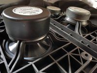
The Driver :
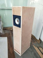
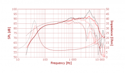
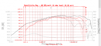
6 months ago I bought a pair of 6.5" full range drivers - aluminum cone - these are from a Chinese brand that some of you may know called Lii Audio.
I'm not gonna bring up all the TS for now, but for a rough idea :
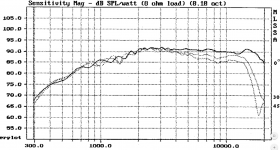
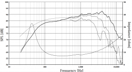
SD = 132cm2 / Qts = 0.617 / Vas = 29L / BL = 6.349 / Fs = 42.853 Hz / Spl = 91.8 db
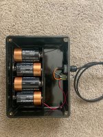
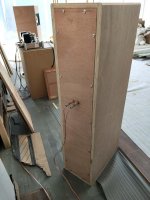
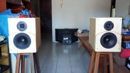
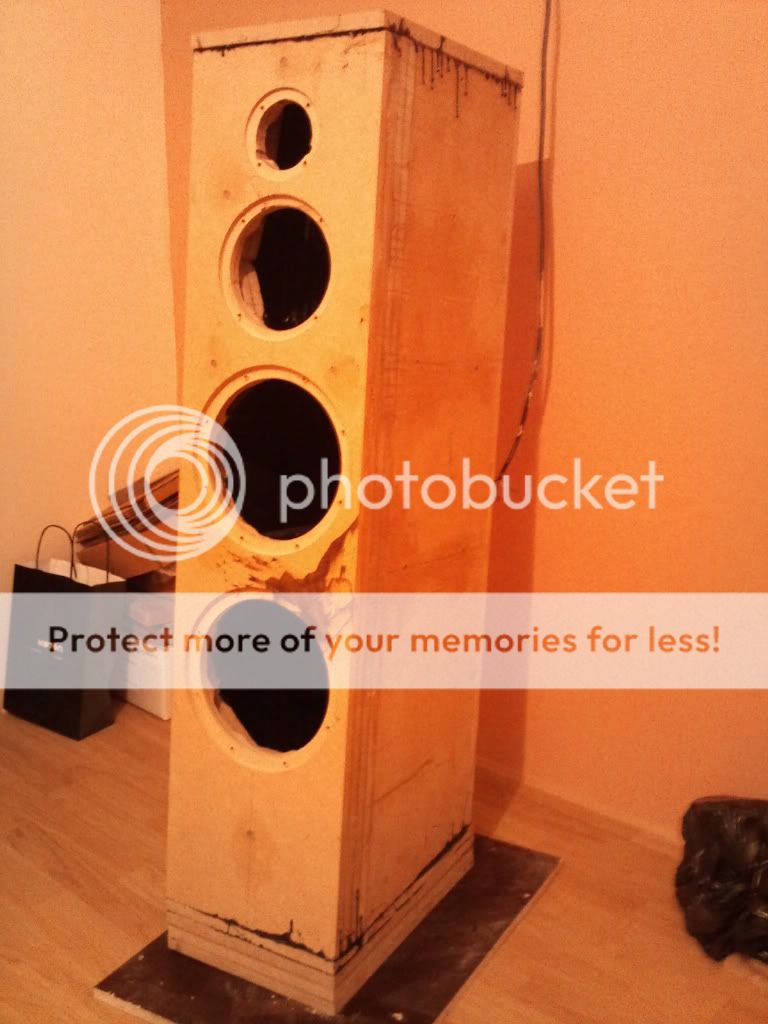
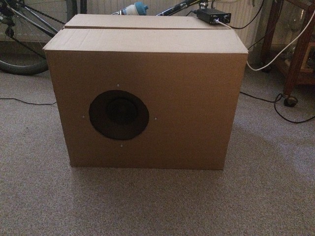
The cabinets :
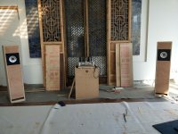
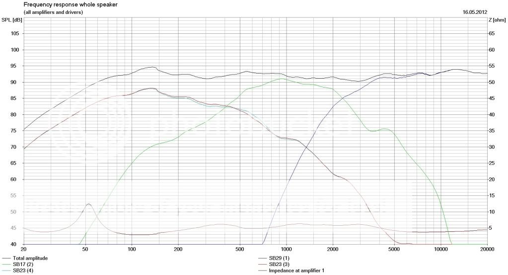
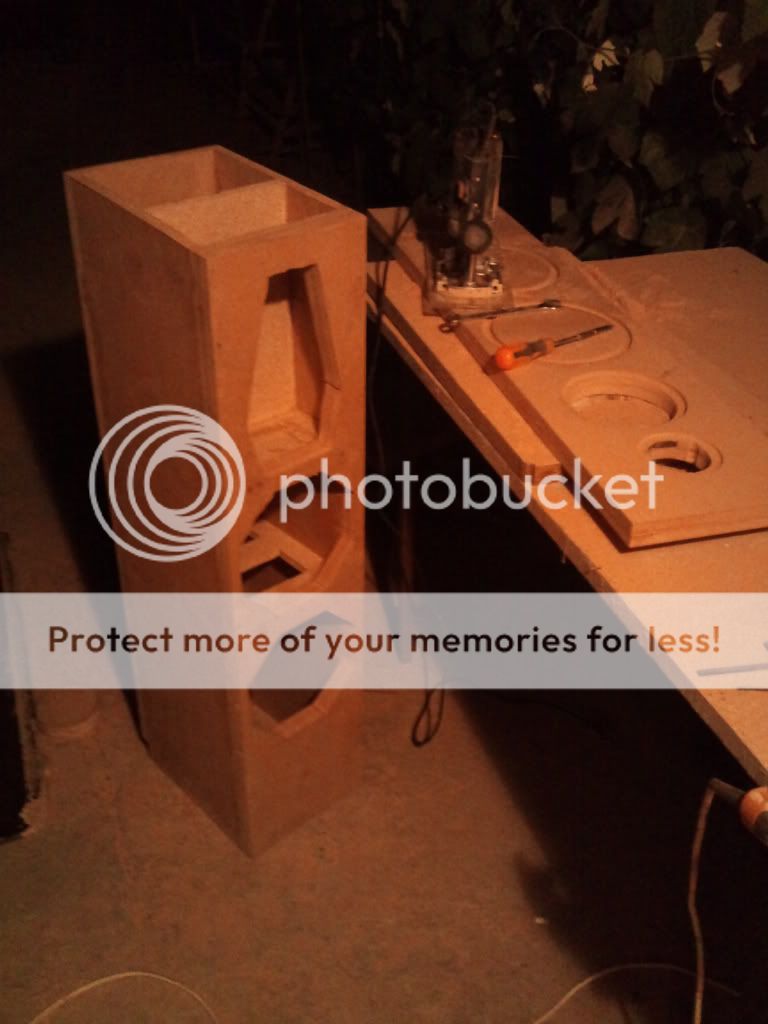
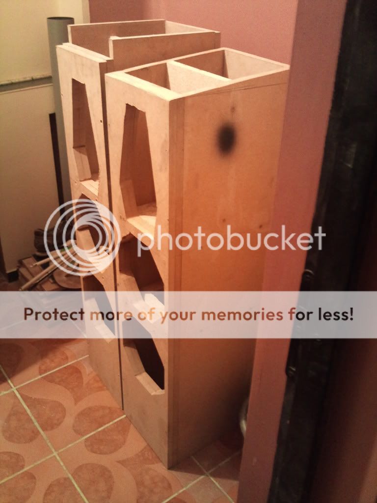
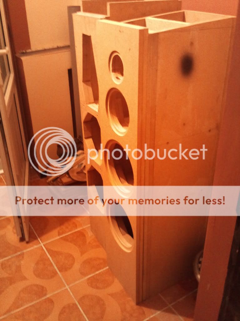
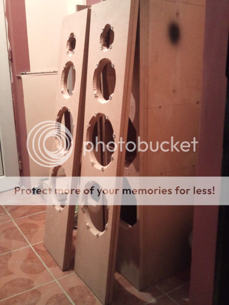
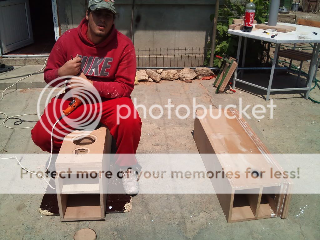
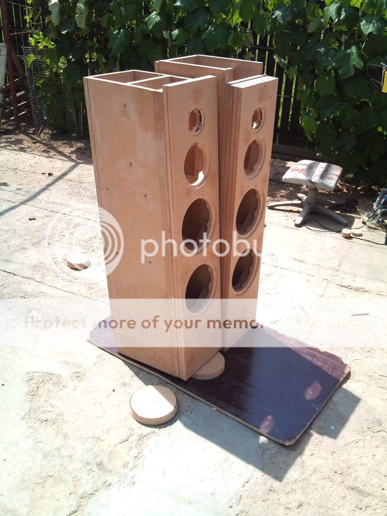
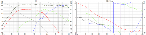
Using Hornresp, I designed and then built a pair of MLTLs for my drivers. In the end they look a bit like some MarkAudio pensil series.
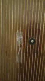
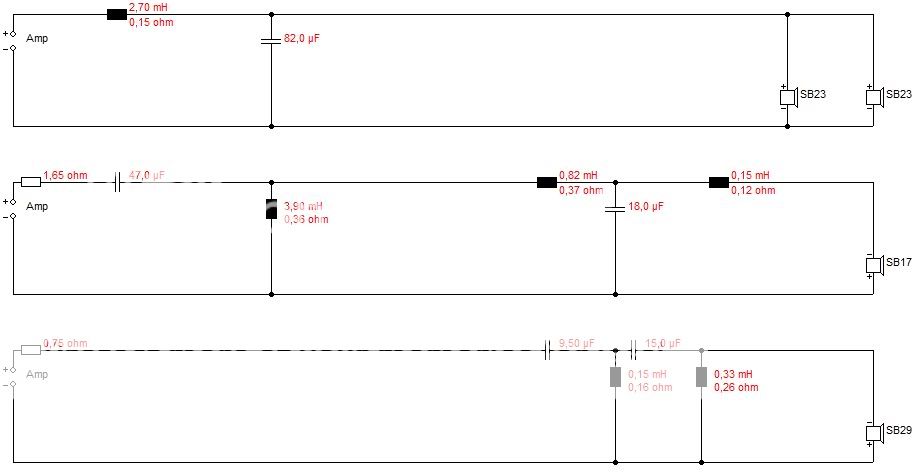
I used no BSC, because I don't want to loose on efficiency (more on this later) however I did try and minimise baffle diffraction (at least for mids and Highs):
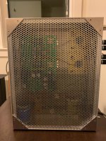
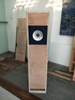
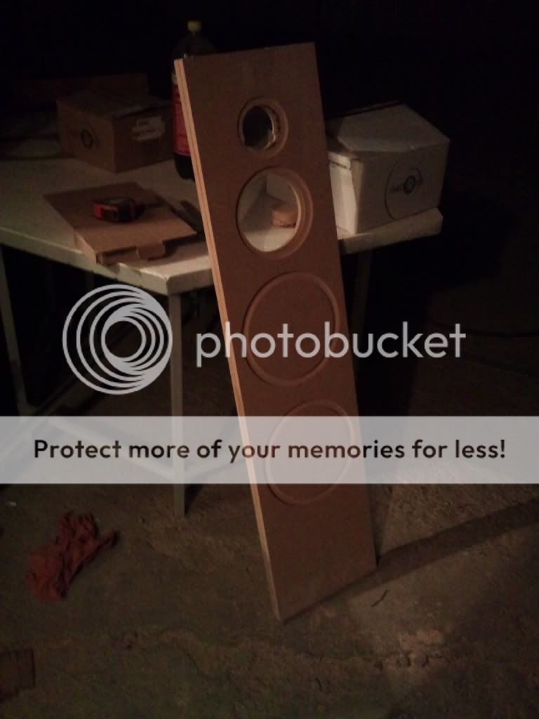
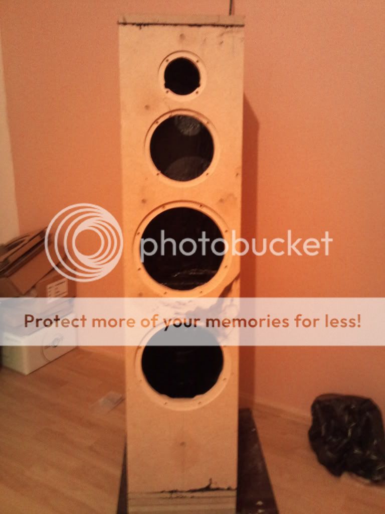
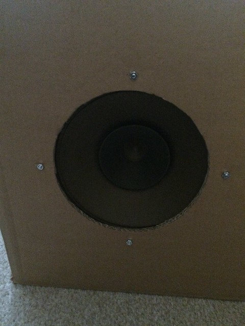
The Baffle part where the driver is placed is on a recessed panel of 20*20cm, and which I then covered with a 9mm thick sound absorbant material (looks a bit like some kind of very stiff felt) that I use for covering walls in home theater rooms when I design homes.
Of course I cut a whole of the size of the driver cone in this material before putting it in place.
When playing music, the difference in the sound is very noticeable whether putting on this part or not, so clearly it is having an effect at canceling or reducing some of the baffle diffraction.
These speakers are (internal dimensions) : H95cm * W20cm * D33cm.
Fb is tuned at 35Hz or 40Hz that just depends if i add or substract an additional layer of plywood (18mm thick) in the horizontal vent located at the bottom of the front baffle. However placing this additional piece or not doesn't to make much of a difference in the end when listening.
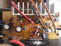
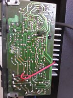
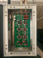
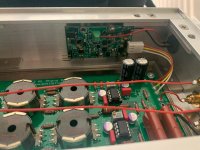
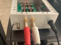
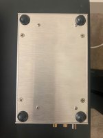
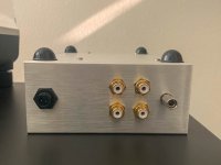
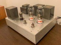
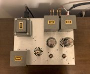
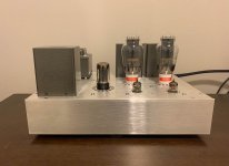
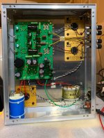
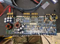
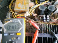
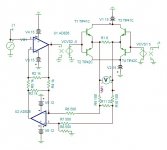
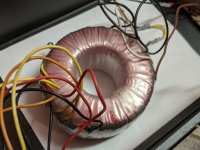
The Amp :
A chinese tube Amp that's got a lot of good reviews from everywhere (the audiophiliac among all but not only).
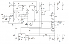
It's the Reisong A10, Ultralinear, with El34B tubes, 6W per chanel.
3 - My impressions up to now :
For a first try, I would say not too dispointed, but can't either say completely satisfied !!!
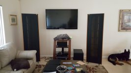
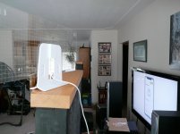
First I placed the speakers about two meters appart, in a room that is about 5-6 meters wide.
The sound coming out was ok but...the bass seamed a little slimish if I placed myself in an about equidistant triangle from both speakers (a more or less normal listening position)
But then if I placed myself almost in line between the two speakers then the bass comes out. So there is Bass.
So then I tried placing the speakers close to the corners of the room (about 80cm inward from each corner) and tilting the front baffles toward the center of the room aka the listenning position and then...Tadah the bass wasn't so slim anymore.
So yes there is thumping bass coming out of these but depends on the position, cause it seems like a lot of it is leaking on the sides.
Then, as there is no BSC applied, I'd say the mids are a slightly too present sometimes, but IMHO it's in an acceptable limit still. As for the highs they feel fine to me.
4 - But then I do have a bunch of problems/questions :
What would you suggest for that bass "leaking" on the sides problem ? BSC ? Change cabinet - side vs front&back - proportions ? You see, MA's pensils designs specify that these cabinet designs don't realy require BSC, so I figured that My design, very similar to a pensil, could also get away without it.
External dimensions are 23.6cm wide (front baffle) x 40cm long (sides). What if I inverted these proportions ? What's your experience with this ?
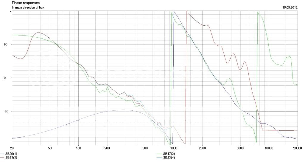
Could it be some kind of bass cancelation in relation to phase or something else ?
Or could it be that my alignment isn't that good ? How should I calculate this then ?
This brings me to another important question : how far can I trust Hornresp in the design of my MLTL ?
Any other serious software options for MLTL ? (besides MJK's mathcad work sheets).
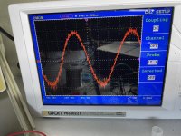
Then, something else that is bothering me is the power :
Granted, it's only a 6W per channel, but if I want to feel a bit of power in the music, I really have to turn the knob all the way up ! the room is basically a 6x6 or 6x7 meters wide.
is that too much for my combination ?
To be honest I am more suspecting the driver or the amp to be wrong somewhere :
a) When running the specs of the driver in WinISD, it tell me that driver's spl is in fact 87db ! If it where you, would you believe more the written specs or what WinISD calculates ?
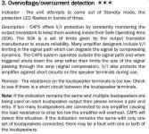
b) As I mentionned before, my tube amp is an ultralinear one, but nowhere can i find the amp resistance output. What I am saying is I don't know if this is actually a high Z amp or not. It is An SET though, as far as I know. So should I consider it a high Z amp ?
And if yes, am I then right to assume that it is because it is a high Z amp that it's not putting out as much power as I would hope...especially if the drivers are in fact 87db one ?
Should I just change drivers ??
If Yes, for what I want, which one of MA would you recommend ? I am considering CHN110 or CHR120. What do you think ?
OK, I am sorry if some of you think this post is just too overwhelming, but I have great respect for many of the people in this forum, you guys know so much, so I sincerely hope you can provide me with hints or answers.
Those of you who will have read it all, thank you for your patience and understanding !
In these very difficult times I truly wish you all the best.
Stay safe, stay very safe ! Don't do anything stupid.
My Best regards to all.