Hello all,
I'm thinking about linear power supply improvement.
Rectifying 3 phases transformer is better than single phase one because we obtain quite DC voltage without any smoothing. So if we use 3 phases transformer and then smoothing capacitors, the ripple quality will be far better than single phase version.
The problem is that in domestic use, we have only access to single phase AC.
What do you think about the usage of a Variable Frequency Drive (VFD) unit to transform single phase to 3 phases AC before supplying a 3 phases transformer ?
Another benefit could be also to increase the frequency of AC lines (up to 400Hz ?) in order to reduce more the ripple with same amount of smoothing capacitors.
I know that VFD generates shopper DC but do you think that transformers could handle that and smooth the current to have sine wave current at secondaries (as AC motor) ?
I had to do a bit of reading up on this subject as I am well out of date but here is stackexchange .com on Electrical Engineering whose website I think highly of-
motor - Using a 3-phase Transformer After a Variable Frequency Drive for Voltage Reduction - Electrical Engineering Stack Exchange
There are many versions of VFD,s for different purposes so you will have to get one appropriate to a 3-phase inductance input mains transformer .
They look pricey.
motor - Using a 3-phase Transformer After a Variable Frequency Drive for Voltage Reduction - Electrical Engineering Stack Exchange
There are many versions of VFD,s for different purposes so you will have to get one appropriate to a 3-phase inductance input mains transformer .
They look pricey.
I would use a three phase LC filter at the converter output if it does not already have one (many don't).
Drives can put out some pretty nasty stuff.
Drives can put out some pretty nasty stuff.
Last edited:
The problem is that in domestic use, we have only access to single phase AC.
I have 3*230V 20A at home in the switchboard.
Pretty standard here in Portugal for 30+ years.
I believe for domestic use we can go up to 3*30A.
I suggest you are looking for a solution when there is no problem for the scenario you are suggesting.I'm thinking about linear power supply improvement.
I'd suggest any form of commercial converter that generates 3ph is only available with 1kW+ power capabilities. A 3-ph output then needs to be transformed to a level suitable for such a large amplifier - and that will need either 3x 1ph power transformers, or a 3ph transformer. And then you need to rectify and filter that in such a way that 300/360Hz ripple and radiated fields do not ingress in to your amplifier's audio circuitry, or any audio equipment or interconnects in the vicinity.
If you need a supply in the 1kW+ region then you really should be looking at a commercial single phase PFC front end conversion, as that should be made sufficiently well to pass mains regulations, and attenuate any 100/120Hz ripple on the DC output rails (as it has 2 active conversion stages to attenuate the ripple). That type of converter has been mature for decades, especially for telecommunications supply, and has also extended down in to the 100's of W mini rack-style modules.
You could also go an alternate route of using a premium PC power supply module (with PFC front end), and use dc/dc conversion to reach the required amplifier DC rails.
Last edited:
....Rectifying 3 phases transformer is better than single phase one because we obtain quite DC voltage without any smoothing. ...snip....
Not THAT smooth. If you already have 3-ph in the room, it is an option, but will need further smoothing for most audio purpose. If you don't have 3-ph handy. "making 3-ph" is the HARD way to go. For one thing, to make the output pretty smooth, you will probably convert the incoming 1-ph AC to "smooth" DC... making DC into AC is hard enough without also regulating or smoothing in the same section.
Here's a sim. 3-ph with no filter (green), 1-ph with no filter (blue), and 1-ph with a simple few-buck capacitor filter (red). The red line is less peak-to-peak amplitude and lower frequency.
Yes, when you get to 50,000 Watt transmitters 3-ph is almost mandatory and there is strong incentive to reduce filtering costs. But I don't think any nice audio runs on unfiltered 3-phase 50/60Hz power.
Attachments

Hello all,
Some of VFD are low power, fanless and are EMC C1, so compatible with domestic environment. For example, this one : Siemens V20 0.75kW 230V 1ph to 3ph AC Inverter Drive, C1 EMC - AC Inverter Drives (230V)
The cost is not so high.
Most of them seem have a DC link to allow the use of DC choke after the first rectifying stage before smooting capacitor.
I agree with most of you that they are noisy (voltage SPWM on the output) and maybe necessitate to add sinewave filter before transformer (LC), or input filter which will increase the cost of solution.
For sure if you need to generate only one or two DC rails, it is not the way to go, choke first filter (LC) are efficient for example.
I'm thinking about this because my project is a multichannel (4 channel for mid and high active speakers) circlotron amplifier and so necessitate 8 floating DC plus the DC for input stages. Having such a high amount of smooth DC rails increases strongly the cost if I use chokes before capacitors.
Please see the comparison of rectifying as PRR shared. For sure, go from 1 to 3 phases make an improvement but not so high. The best interest is maybe to be able to increase the frequency (seems up to 400 Hz easily for standard transformer ?). The ripple with same capacitor is very low at 400 Hz !
Attachments

If you need a supply in the 1kW+ region then you really should be looking at a commercial single phase PFC front end conversion, as that should be made sufficiently well to pass mains regulations, and attenuate any 100/120Hz ripple on the DC output rails (as it has 2 active conversion stages to attenuate the ripple). That type of converter has been mature for decades, especially for telecommunications supply, and has also extended down in to the 100's of W mini rack-style modules.
Interesting, could you please say more about that ?
What is the direct benefit of PFC vs standard rectifier on the output ripple ?
Last edited:
You mean input 400Hz into a Standard 50Hz/60Hz mains transformer ?
Not designed for it and you ( or I ) could go into engineering design reasons why not .
Yes you can buy specialised "converter transformers" from 50Hz -400Hz
but just (trying ) to run a bog standard EU/UK mains transformer at 400Hz and expect it to operate properly ?
Why the obsession with 400Hz ?--do you work in the aircraft industry ?
Nevertheless here is a website selling 400Hz three phase transformers -
400 HZ THREE PHASE ISOLATION TRANSFORMERS - L/C Magnetics
You mean input 400Hz into a Standard 50Hz/60Hz mains transformer ?
Not designed for it and you ( or I ) could go into engineering design reasons why not .
Yes you can buy specialised "converter transformers" from 50Hz -400Hz
but just (trying ) to run a bog standard EU/UK mains transformer at 400Hz and expect it to operate properly ?
Why the obsession with 400Hz ?--do you work in the aircraft industry ?
Nevertheless here is a website selling 400Hz three phase transformers -
400 HZ THREE PHASE ISOLATION TRANSFORMERS - L/C Magnetics
I'm not working in the aircraft industry ! 🙂 But it seems aircraft industry has choosen 400Hz to reduce the size of transformer and improve the smoothing of filters. It is an interesting experience feedback I think.
Toroidal transformers we can buy easily (Audiophonics for example) seems able to handle 400Hz by custom. It seems this 400Hz limit is usual for "standard" magnetic circuits (basis transformers, AC motors, etc). Am I wrong ?
Increasing frequency will help a lot to reduce transformer size and ripple. At extreme it's for sure SMPS, could be also a good solution (more than 30kHz).
The Siemens drives are not configured or suitable for your application - they are specifically configured for driving 3ph motor windings, and have special startup and protection and control parameters, which the user needs to configure for the motor type. They also operate with PWM switching frequency that is centred around 8kHz and has relatively large switching amplitude (check out the special precautions for screening the cable to the motor and that the motor then acts as its own shield). If you were really keen (or desperate) you could enquire to their technical help line to get clarification on if they could be configured to operate in to a transformer isolated rectified load.
Perhaps if you revert to the simplest path of using standard separate B+ supplies, and work through all the details of how they should operate, along with how to manage protection if a supply fails, and how to minimise total system hum and noise, and relate that to what each power supply really needs.
Perhaps if you revert to the simplest path of using standard separate B+ supplies, and work through all the details of how they should operate, along with how to manage protection if a supply fails, and how to minimise total system hum and noise, and relate that to what each power supply really needs.
Not just about that Wankel ( no relation to the German engine designer ?)
400Hz is not new its 75 years old ( or more ) used in Lancaster bombers in SHORT lengths to overcome radio transmitters/radar etc interference - not good in long runs .
They also used old school equipment that DIDN'T produce all this "digital hash " that you get in modern compact solid-state design as it would be a waste of time doing it to have it injected by their own generating equipment .
Young people seem to think all modern stuff is innovative --its not and many times it goes backwards in quality engineering .
John Logie Baird designed a stereo colour TV way back in the 40,s before he was killed .
No drive will successfully run a three phase rectifier load; they will trip out on either overload or motor winding failure from their protection algorithms. It expects a highly inductive passive load. Give it a discontinuous load and it fails.
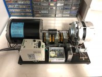
To do this right you would need something like the attached. A motor-generator set, where the generator produces a nice clean sine wave and has no problem driving nonlinear loads. Not that I at all recommend the path you are headed on, it is a lesson in futility. Taking AC, converting to DC, reconverting to AC, then back again to DC - you see the insanity in that right?
Rectify/filter your single phase as has been done for the last 100 years and be happy with it.
Attachments
No drive will successfully run a three phase rectifier load; they will trip out on either overload or motor winding failure from their protection algorithms. It expects a highly inductive passive load. Give it a discontinuous load and it fails.
To do this right you would need something like the attached. A motor-generator set, where the generator produces a nice clean sine wave and has no problem driving nonlinear loads. Not that I at all recommend the path you are headed on, it is a lesson in futility. Taking AC, converting to DC, reconverting to AC, then back again to DC - you see the insanity in that right?
Rectify/filter your single phase as has been done for the last 100 years and be happy with it.
Many thanks for your experience in using VFD.
Yes I agree with you. Going into details and from all of your feedbacks, it seems not a way to go.
So the best is either the standard linear solution (AC - transformer - rectifier - (choke or not) - smooting capacitor) or to use SMPS (resonant topology ?) in order to take benefit of outband frequency noise, smaller transformer and higher efficiency.
Sounds just like an insane SMPS 😀Taking AC, converting to DC, reconverting to AC, then back again to DC - you see the insanity in that right?
Mona
Point taken, with the clarification that our SMPS utilizes high frequency single phase AC outside of the audio band, taking advantage of smaller transformer weight/cost and fantastic efficiency. Additionally, it regulates tightly.
Using the AC drive to produce the same 60Hz at three phase does not provide nearly the same benefit, nor does it regulate.
Using the AC drive to produce the same 60Hz at three phase does not provide nearly the same benefit, nor does it regulate.
Many thanks for all your feedbacks, it is very helpfull to guide my thoughts about that !
I will continue my investigations into SMPS. But I need custom to have floating outputs.
I will continue my investigations into SMPS. But I need custom to have floating outputs.
if 400V 3 phase is available in the room then it makes sense to use it to power big subwoofer amps....
There are small cheap ebay smps that are titled 'inverter' and have 150W rating and use a 12Vdc input. I have a few, and they have an isolated secondary winding with a few taps, which can be rectified and filtered on the small pcb to derive a variety of fixed B+ levels for valve amps. Although there is no feedback regulation for the B+ level, it is surprisingly stiff when the 12Vdc input is constant. The output power capability depends on the FET heatsinking, but even the small heatsinks supplied with the module stay cool for 40W B+ loading. 8 of those modules could use a common 12VDC supply, and there is no issue from mains frequency related hum.
'150W' 12VDC isolated 25kHz step-up smps for B+
'150W' 12VDC isolated 25kHz step-up smps for B+
Last edited:

- Home
- Amplifiers
- Power Supplies
- Variable Frequency Drive for 3 phases linear power supply