You are using an out of date browser. It may not display this or other websites correctly.
You should upgrade or use an alternative browser.
You should upgrade or use an alternative browser.
Filters
Show only:

Muting transistor failure mode
- By Dfhaii
- Solid State
- 2 Replies
Hello,
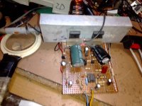
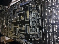
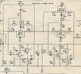
I'm looking to repair my Marantz PM6002 amplifier, symptoms are one channel is intermittent, mainly silence, some noise and sometimes works fine.
I have a service manual for the amp and it looks like the signal flow is input sockets, into a mux (LC78212) for source select, followed by a unity gain buffer, volume pot, tone control, and then amplifier.
The symptoms persist wherever the pot is in the range, and happens both with the tone control switched in and out, it also persists on all the inputs which rules out the input mux (there are two, depending on which input is used.)
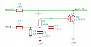
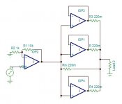
There are a bunch of opamps, and of course the amplifier, but my current suspicion is the muting circuit, I've attached a transcription of it for one channel (CE connections are as shown in service manual.) Mute is driven from a microcontroller and is 0/5 V.
Does this sound like a resonable diagnosis, and is this a common failure mode for muting transistors?
Thanks!
I'm looking to repair my Marantz PM6002 amplifier, symptoms are one channel is intermittent, mainly silence, some noise and sometimes works fine.
I have a service manual for the amp and it looks like the signal flow is input sockets, into a mux (LC78212) for source select, followed by a unity gain buffer, volume pot, tone control, and then amplifier.
The symptoms persist wherever the pot is in the range, and happens both with the tone control switched in and out, it also persists on all the inputs which rules out the input mux (there are two, depending on which input is used.)
There are a bunch of opamps, and of course the amplifier, but my current suspicion is the muting circuit, I've attached a transcription of it for one channel (CE connections are as shown in service manual.) Mute is driven from a microcontroller and is 0/5 V.
Does this sound like a resonable diagnosis, and is this a common failure mode for muting transistors?
Thanks!
Attachments
Constant directivity no baffle... with a baffle...
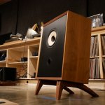
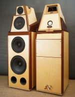
On Dec 28th I will be taking delivery of a pair of 18" drivers and thus will be in possession of a full complement of drivers for what is supposed to be a ~full range constant directivity no-baffle speaker. Trouble is, I don't want it to look like a no-baffle speaker.
My woodworker guy is waiting on me to pull the trigger on the design, but I am uncertain about how to make something that looks like a baffle but does not interfere with imaging in any way shape or form. Would the baffle need to be perforated or would a "reasonable" open slot around the driver be enough?
I will enclose a pic below to make myself understood. The drivers are planned to be suspended. Necessary ropes not shown.
For reference, crossover points are planned at 150 Hz and 750 Hz. Mid driver is an Audio Nirvana CF Super 10, compression driver is 18Sound ND 1480 A on XT1464 horn. 18" are FH510 from Faitalpro (yes, low QTS). System will be fully active for time alignment and EQ.
Attachments

Li-ion charger and boost converter for active guitar pickups
- By Rootz
- Power Supplies
- 7 Replies
For years I've been playing a guitar with active EMG pickups and active tone controls. About a month ago I decided to rebuild the guitar in a more genuine Stratocaster fashion. This means also having a pickguard, which the old one didn't have.
Now EMG's normally are powered by 9 or 18V from one or two 9V batteries. As the body I use isn't utilised with a dedicated battery compartment, I opted to experiment a bit with a Li-ion cell and a charger and an asynchronous boost converter (on the same board). I do not have room for 2 batteries anymore. Also, being able to charge via USB is hugely convenient, even with the long battery life with EMG equipment. Just charge before a gig and you're safe.
The charger is a TC4056a, the converter is based on a SDB628. The results were rather disappointing, even for stuff from aliexpress. There is a pretty big hiss and a bit of hum present in the output signal of the pickups. I added a not so well calculated LC filter after the converter and got slightly better results.
Obviously, aliexpress might not have been the best bet for reliable and more than basic hardware in the first place. Are there safe and reliable options available to work with li-ion cells this way? For now I use a 9V battery with a charge pump. That is silent but not as convenient as I'd like. Suggestions are more than welcome.
Resistor Value
- Car Audio
- 28 Replies
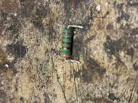
Anyone know the value of this resistor ?
I’ve never seen an orange band at the end
I’ve never seen an orange band at the end
Attachments
Phillips CDR778 Recorder Laser needs replacement
- By morewine
- Digital Source
- 1 Replies
Where can the laser be purchased?
Thanks
Thanks
Fern roby raven box vs 1 : 1.618 ratios
- By norman bates
- Full Range
- 23 Replies
Just spit ballin here..
I'm thinking w8-2145 in either fern roby raven sized box (19.25" wide by 24.5" tall, minus stand), or similar without stand 19" wide by 29" tall.
When the raven is on its stand, it is darn near 29" tall.
Definitely need 5mH baffle srep inductor, maybe more.
My similar 1:1.618 (w8-2145) needed big bass boost for my ears when off the ground, even some when on the floor.
Not much bass beyond 7' away in my big room.
Do you think it helps to offset the driver also (vertically anyway) ?
Here are some links to the raven (using seas exotic f8).
The Ravens |
Fern & Roby
Fern & Roby Raven Loudspeakers | Review | Part-Time Audiophile
Fern & Roby Send A Raven - AXPONA 2019 | AudioHead
CAF 2018: Fern & Roby – Twittering Machines
CAF 2018: Fern & Roby – Twittering Machines
https://forum.audiogon.com/discussi...good-the-bad-and-the-ugly/post?postid=1829142
And a review of seas f8 from back in 2011
https://www.tnt-audio.com/casse/seas_exotic_e.html
My wife agrees with me, the walnut sides are gorgeous !!!!!!!!!!
Attachments
WTB : RTX 6001 / QA 401
Hi all ,
I am looking after an audio analyser like one of these two :
RTX 6001 or QA 401
Thanks in advance
Fabrice
I am looking after an audio analyser like one of these two :
RTX 6001 or QA 401
Thanks in advance
Fabrice
Best Speaker types for my room + room correction tips
- By jayce996
- Room Acoustics & Mods
- 5 Replies
Hello there,
i'm looking at upgrading my speakers and my living room.
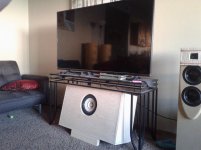
Here is the configuration of it:
20201218_094253.jpg - Google Drive
20201218_094633.jpg - Google Drive
As you can see the room is 8.2m long with 3.5m large, 2.5m height, in one side there is a sliding glass door and on the other side , it is open all 4.2m long to the kitchen & dining room.
Today i've 2 JBL XPL200 but i was looking at changing it by either open baffles but i think i do not have enough space next and behind the speakers for this. my configuration is in a 5.0 mode as of now.
I was looking at JBL 4343/4344 like speakers position next to the wall or even line array speakers or ...
in the ceiling i'm able to integrate speakers , so i'll certainly see for putting 2 to 4 speakers in the ceiling as well.
All my gears are in the little room with the white sliding door as you can see on the picture. i've a Pre-amp EMOTIVA XMC1, some power amps like a crown K1 or an AIWA P22, and crossovers.
My questions for you guys are:
- what kind of speakers would be the best for such type of living room configuration? OB, cornwall/4343 like speakers, Voigt speakers with TB W8 1818, Line array, ...
- And also what kind of room treatment would i have to do in order to optimize the sound quite a bit knowing that today i'm using DIRAC Live for room correction?
Thx a lot !!!
i'm looking at upgrading my speakers and my living room.
Here is the configuration of it:
20201218_094253.jpg - Google Drive
20201218_094633.jpg - Google Drive
As you can see the room is 8.2m long with 3.5m large, 2.5m height, in one side there is a sliding glass door and on the other side , it is open all 4.2m long to the kitchen & dining room.
Today i've 2 JBL XPL200 but i was looking at changing it by either open baffles but i think i do not have enough space next and behind the speakers for this. my configuration is in a 5.0 mode as of now.
I was looking at JBL 4343/4344 like speakers position next to the wall or even line array speakers or ...
in the ceiling i'm able to integrate speakers , so i'll certainly see for putting 2 to 4 speakers in the ceiling as well.
All my gears are in the little room with the white sliding door as you can see on the picture. i've a Pre-amp EMOTIVA XMC1, some power amps like a crown K1 or an AIWA P22, and crossovers.
My questions for you guys are:
- what kind of speakers would be the best for such type of living room configuration? OB, cornwall/4343 like speakers, Voigt speakers with TB W8 1818, Line array, ...
- And also what kind of room treatment would i have to do in order to optimize the sound quite a bit knowing that today i'm using DIRAC Live for room correction?
Thx a lot !!!
super vas
- By latala
- Solid State
- 10 Replies
I have been experimenting for a while now with transistor amplifiers say for the last 50 years or so
I now feel that the heart of any good amplifier lies with the VAS stage
Over the lockdown I have been experimenting with a no of circuits What I am after is a super VAS does any one have details re device and schematic
emitter follower cascode etc All advice and guidance gratefully received
Trev
I now feel that the heart of any good amplifier lies with the VAS stage
Over the lockdown I have been experimenting with a no of circuits What I am after is a super VAS does any one have details re device and schematic
emitter follower cascode etc All advice and guidance gratefully received
Trev
Any chance of a J2 to F8 conversion program?
- By rickmcinnis
- Pass Labs
- 8 Replies
I use a J2 along with an SIT 1 to drive the two sections of a Klipsch K401 based MEH horn based upon the idea of the very prickly Chris A frm the Klipsch forum.
It is a very good sounding speaker. Using the CELESTION Axi Periodic compression driver which I find to be exceptionally fine. Much better than the JBL Truextent combo I was using.
Sorry for all of that.
I am intrigued by the pure single ended aspect of the J8 - thinking it would blend better with the SIT 1.
Since one channel of a J2 has two of the precious SEMISOUTH devices these could be used to make two channels of of an F8. One part of me likes the idea of using four amplifiers to drive each of the woofers in the speaker instead of having them wired in series.
I have already converted my amps into mono blocks so the conversion would be fairly simple - two two channel amplifiers instead of a mono ampllifier.
The question is: is there any chance something like this could be done? Or far more precisely, any chance Mr. Pass would sell a PCB to those who are J2 owners? Maybe an exchange program would be better still to keep errant boards off of the market. Send in one J2 channel's PCB and get two F8 pcbs.
Would our great benefactor consider such a project in the New YEar?
Elevated filament supply
- By bosch
- Tubes / Valves
- 24 Replies
Hi
quick question from a puzzled amateur...
I've recently finished my first amp build and there is a bit of hum through the speakers so I'm working my way through the various ideas I see in forums such as this in an effort to remove it.
An article on Valve Wizard (Merlin Blencowe) talks about elevated filament voltage and as I have the parts I thought I would test this out.
On the 6.3V filament supply I have a virtual center tap which normally goes directly to ground so I setup the circuit like this which I calculate should elevate the virtual center tap to about 42V

What puzzled me was that the voltage on the B+ side of the 1M resistor was 470VAC but on the other side of the same resistor my DVM reads 0VAC.
I am very new to this so it may well be a simple explanation but I expected to see 42VAC.
Many thanks.....
quick question from a puzzled amateur...
I've recently finished my first amp build and there is a bit of hum through the speakers so I'm working my way through the various ideas I see in forums such as this in an effort to remove it.
An article on Valve Wizard (Merlin Blencowe) talks about elevated filament voltage and as I have the parts I thought I would test this out.
On the 6.3V filament supply I have a virtual center tap which normally goes directly to ground so I setup the circuit like this which I calculate should elevate the virtual center tap to about 42V
What puzzled me was that the voltage on the B+ side of the 1M resistor was 470VAC but on the other side of the same resistor my DVM reads 0VAC.
I am very new to this so it may well be a simple explanation but I expected to see 42VAC.
Many thanks.....
Build from the ground
- By LikeLeon
- Construction Tips
- 3 Replies
My Kenwood KA4002 was rejected from a store to restore because of dust and water damage.
I don't want but i go to restore this amp myself.
* get it back from the store.
Greets Leon.
I don't want but i go to restore this amp myself.
* get it back from the store.
Greets Leon.
Marantz CD43 / 53 / 63 Service Manual
- By ALW
- Digital Source
- 69 Replies
I know there's a number of owners and tweakers of this player out there, I have the service manual for these players, and have scanned it into an Adobe PDF document.
It's 9.2Mb - if anyone wants a copy I'll place it on a website somewhere for download, let me know.
I also have some scans of the main PCB tracks, with the power supply traces highlighted (5V, +12V and -12V) for those that fancy tweaking and adding additional regulation, it makes it a lot easier to follow.
There's no mention of copyright anywhere within the manual, so it should be fine.
Andy.
Active crossover for AT 10A772510KAP; ATC SM75-150-AOS; Scan Speak D3004 / 6640
- By fred sonnen
- Swap Meet
- 18 Replies
The crossover itself is fine. I suppose there is some noise coming from the power supply, but it is disturbing. Therefore I sell the crossover as a defect.
It shouldn't be difficult for DIY people to get the crossover working properly. And above all to understand the circuitry made by professionals and to use it for their own purposes.
Used parts:
Crossover: ABACUS electronics - Aktuelle Meldungen und neues aus dem Labor
Power supply: Sjöström SSR-03
Case: Modu Galaxy Maggiorato
Connections: 8x Neutrik RCA
Price: 200.- EUR plus postage insured DHL shipping within EU (& GB)
And as always:
Private sale, guarantee and exchange excluded.
ScanSpeak 15w/8534
Hello everybody. I ve posted it in a wrong section first. Sorry. Just wandering if anyone has tested or used new classic 15w with phenomax cone ? Would appreciate first hand impressions. Thx Peter
Amp kit for 85-89dB efficiency speakers
Hello Folks,
In the last few weeks, I have been pondering all over the place about the pros and cons and merits of various First Watt designs (mainly F5,F6,J2,M2 Aleph J,etc.) I understand they are all unique designs, it can get quite confusing and frustrating trying to find the right kit. My question was probably asked a millions times before so I apologize in advance.
Seeking for clarity and advice from the community on most appropriate Pass amp kit t to match my current line of speakers as I am not planning on upgrading them any time soon :
1. Angstrom 500S 3 way full range design 89dB 1watt/ 1 meter 45Hz-20kHz +/- 3 dB). Impedance 8 Ω (MOSTLY USED)
2. Magnepan 0.7i 2 -Way/Quasi Ribbon. Freq. Resp. 45-22kHz ±3dB. Sensitivity, 86dB/500Hz /2.83v. Impedance, 4 Ω
Right now, they are hooked up to Class AB & Class D amps. Listening mostly to low/moderate levels.
Secondly, also important are good tutorials and guide for sourcing the parts and build instructions - my building skills are just average and will need a good manual. Aleph J instructions appear to be easy to follow.
Many thanks in advance for your appreciated feedback!
Theta Data Basic - needs repair
- Swap Meet
- 1 Replies
Theta Data Basic. Coaxial output only. Remote included. Powers up. Lovely cosmetic shape. Drawer does not open and needs repair.
$300 OBO...


$300 OBO...
Repair separated voice coil from cone on Ultimax 8"
- By xorgonix
- Subwoofers
- 3 Replies
Hi all...
I have an older ultimax 8" driver where the voice coil has become unstuck from the cone.
There is no adhesive remnant on the cone, there is a somewhat pliable glue still on the voice coil itself.
I understand that this was a problem for some of the early renditions of this driver.
Has anyone fixed theirs?
I'm thinking about trying to gently clean off the old glue with a paint brush and solvent (upside down so the solvent won't drip down into the coil), and then using either polyurethane or epoxy to reglue...
Any thoughts?
What is going on here with this grounded cathode stage?
- By Windcrest77
- Tubes / Valves
- 20 Replies
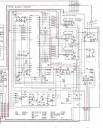
In this schematic what is going on here with the grounded cathode stage? I get that C1 is the stage decoupling capacitor correct? Its purpose is to prevent motorboating right? It wraps the whole B+ just like a power supply filter except closer to the tube right? But what is happening with C2, R6 and R7 here? Is not C2 also a stage decoupler of sorts? I don't remember ever seeing a plate load divided in half like this. I thought when you put an electrolytic all the way across the tube and its two resistors, but near it, then that was your stage decoupler. Is this some other way To decouple a stage? R6 and R7 are not dividing any DC here, the plate resistor is still their sum 44k. Confused.
Here is the article where I found this:
Welcome to the most complete do it yourself guide on the D. T. N. Williamson tube amplifier., chapter 3 , The Circuit
Here is the article where I found this:
Welcome to the most complete do it yourself guide on the D. T. N. Williamson tube amplifier., chapter 3 , The Circuit
Attachments

Building a bluetooth speaker from scratch
- By Luan Augusto
- Construction Tips
- 0 Replies
Hello everyone.
I'm new to the audio world and I'm willing to build a bluetooth speaker from scratch.
I do understand a little bit of eletronics so I think I'll be able to put everything together, but I'm not sure if the components I choose will give me a good result, I've being studying about DIY speakers for about 20 days and I would appreciate a feedback about what I could change to get the best results.
Here the components:
2x AIYIMA 3inches 4ohm 40W full-range speaker
2x GHXAMP 1.25inch (30mm) 8ohm 10W neodymium
2x Harman/Kardon passive radiators 4 inches (121mm)
1x WAVGAT TPA3116 50w + 50w amplifier
2x PAPRI Axial Capacitor 3.3uf 400vdc
5x Thermostat 250V 5A 60ºC
8x BASEN 18650 battery 3.7v 30a
1x WAVGAT 4S 30a 14.8 protection circuit board
1x KingWei Charger 16.8v 2.0a
1x 24v switch
Schematics:

I also created a wishlist on aliexpress just to be easier to check the components I picked, here is the URL for the wishlist: AliExpress.com : My AliExpress
Also, if I use a 2-way crossover instead of the axial capacitor it will give me best results or it will be similar?
Thank you for your help.
I'm new to the audio world and I'm willing to build a bluetooth speaker from scratch.
I do understand a little bit of eletronics so I think I'll be able to put everything together, but I'm not sure if the components I choose will give me a good result, I've being studying about DIY speakers for about 20 days and I would appreciate a feedback about what I could change to get the best results.
Here the components:
2x AIYIMA 3inches 4ohm 40W full-range speaker
2x GHXAMP 1.25inch (30mm) 8ohm 10W neodymium
2x Harman/Kardon passive radiators 4 inches (121mm)
1x WAVGAT TPA3116 50w + 50w amplifier
2x PAPRI Axial Capacitor 3.3uf 400vdc
5x Thermostat 250V 5A 60ºC
8x BASEN 18650 battery 3.7v 30a
1x WAVGAT 4S 30a 14.8 protection circuit board
1x KingWei Charger 16.8v 2.0a
1x 24v switch
Schematics:
I also created a wishlist on aliexpress just to be easier to check the components I picked, here is the URL for the wishlist: AliExpress.com : My AliExpress
Also, if I use a 2-way crossover instead of the axial capacitor it will give me best results or it will be similar?
Thank you for your help.
Inductor type for baffle step
- By noviygera
- Full Range
- 4 Replies
I have a question on the type of inductor to use (gauge and core type) in my application:
1-1.2mH inductor and 5-10ohm resistor are flattening out the response nicely.
This is the project and the baffle step is for the SB Acoustics FR drivers.
omni BT speaker design -
Techtalk Speaker Building, Audio, Video Discussion Forum
Inductor:
1. small as possible to not degrade sound quality
2. baffle step in a FR driver. sealed box.
Resistor:
1. wattage?
thanks!
Preamp selection advice please
So I would like to start my next preamp project but can't decide between the Mezmerize or the B1 Korg.
I currently have a B1 and a Dodd tube buffer driving a F5 or Folsom's chip amps.
I think I will be building Folsom's new 7293 version as well.
Speakers are currently Hawthorne Audio open baffle but soon to be GR research open baffle with a separate low frequency section.
Which preamp do you think best suits my system ?
I can't seem to find any comparisons of the 2 preamps on the forum.
Extremely simple amplifier (4 transistors) with low THD.
- By Renbrant
- Solid State
- 40 Replies
Hello friends,
Today I tested an extremely simple project (4 transistors) developed and produced by a friend of mine from Brazil.
His website is this: AlfaKits Eletrônica
The cool thing is that on his site is shared free of charge the electrical scheme and layout of the PCB for those who want to produce for their own use. Production for sale is prohibited.
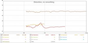
I was impressed by the level of THD he achieved with a simple 12 to 15V power supply and only 4 transistors.
Check out the results:
I couldn't post the photos. Following is the link to the results:
RB Eletronica - UNO
I'll publish on my YT channel the details about that test, soon.
YouTube
Today I tested an extremely simple project (4 transistors) developed and produced by a friend of mine from Brazil.
His website is this: AlfaKits Eletrônica
The cool thing is that on his site is shared free of charge the electrical scheme and layout of the PCB for those who want to produce for their own use. Production for sale is prohibited.
I was impressed by the level of THD he achieved with a simple 12 to 15V power supply and only 4 transistors.
Check out the results:
I couldn't post the photos. Following is the link to the results:
RB Eletronica - UNO
I'll publish on my YT channel the details about that test, soon.
YouTube
Fostex fe168e∑ Cabinets
- By AlexiCroteau
- Full Range
- 2 Replies
Hello all. i'm looking for some ideas to make a pair of blh towers. besides the cabinet suggestion from fostex, are there any ohter good suggestions.
i have a cnc, so i can go pretty wild on the design
i have a cnc, so i can go pretty wild on the design
AudioPipe 25001D output issues
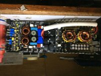
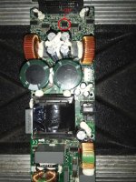
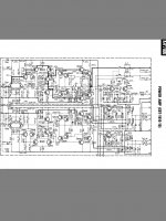
Good day guys, I’m having some issues with output stability on this amp. It was brought to me in this condition power supply fully functional, output missing but I need to make some tests to see if driverboard is functional before I put the output mosfets back in the amp.
Previous tech says the output was burnt/shorted the replaced sets are overheating rapidly especially the rear four near the capacitor bank across from the output relays.
I’ve sent a pic of the amp board and driver board.
Previous tech says the output was burnt/shorted the replaced sets are overheating rapidly especially the rear four near the capacitor bank across from the output relays.
I’ve sent a pic of the amp board and driver board.
Attachments
Preamp hiss noise
- By FOXYE
- Tubes / Valves
- 18 Replies
Hello,
I have amplifer that make low hiss noise through the speakers.
After isolating the source of the noise, it was discovered that tube pre in the unit makes it.
It's clean hiss, not buzz, not hum. and the tubes are stock 12AX7.
And circuit runs on 220V and heater psu is 6.5V DC.
Is there a way to eliminate the noise?
Any ideas welcome.
Building Illuminator-4 (design by T. Gravesen)
I have been building these speakers for 4 months now. In case someone else is thinking about doing the same, I will share some experiences and photos of the process.
When I choose this kit there was zero reviews or experiences with this particular model. Only source of information is Mr. Gravesen very detailed website describing any and all aspects of speaker building. There are really good reviews about his other designs, but none (yet) of the Illuminator-4.
Kind of unnerving when kit just containing crossovers, internal wiring and elements set you back around 4.000EUR. Depending on your taste of wood, painting, speaker terminals etc. add another 500 or more
When the kit is delivered at you door you get the funny feeling. This is either the last big DIY speaker project you will ever do (since spending another 4.5k is not really happening) or it will be a fantastic experience going where very few other have gone before and getting a speaker in same class as the Wilson Alexia.
Here is link to speaker site:Illuminator-4
This is how his version looks:
Attachments
Rotel RA-980BX blowing fuses
- By dimliakos
- Solid State
- 11 Replies
I ΄ve recently bought for cheap a Rotel RA-980BX integrated amplifier. The amp was in a very bad state inside and looked abused and very dirty. Looked like it was played in a beach bar. Many of the capacitors had been rotten as well as many resistors and diodes. I ΄ve replaced all of them one by one with quality replacements. Critical parts as the rectifiers, the power transistors and the main caps looked OK. So when I tried to power up the amp the fuses blown imeediately so I decided to start using a braker type fuse cos I knew that this would go very far. The tranformer gives 42volt across red - black and 42v across orange -black and 84v between red - orange. I ΄ve checked the rectifiers of the board and the seem to be working fine. I ΄ve found that one of the 250v capacitor c905 was faulty and replaced but not luck. I΄ve noticed that there must be a great amount of surge or a big short cause the 10amp bracker drops imediately on both suplies ac1 ac2. I΄ve checked all of the power transistors by desoldering them off the board and they looked fine. I tried to power up the amp with the transistors unconnected and guess what the braker went off again. I also noticed that the R623 and R624 went blown. I don΄t know what else to look for or what is the proper checking procedure so I am going to need your help.I really need this thing to start working again..
Amplimos 2sk82/28 push pull build thread
- By slr 5000
- Solid State
- 33 Replies
I guys
I have some sony 2sk82/2sj28 sitting around doing nothing and have decided to try one of the schematics on the Amplimos site
I have permission from the owner Francesco to try to get some boards made and a few circuit recommendations so we are good to go
I hope others will join in along the way as I think these parts have a lot of potential and are still easy to get (expensive though)
any interest please chime in
below is the circuit of interest
http://www.amplimos.it/images/V-fet complementary 2SK82_2SJ28_Ver_B.bmp
Sheafer
Best way to soft start 3 transformers?
- By thuanth43
- Power Supplies
- 8 Replies
So I’m on plan for an amplifier that has 3 separate transformers (2x 150W, 1x 300W). Clearly I don’t want to press a power switch for all of those transformers without some sorts of soft start. The way the amp working requires the 300W transformer goes first and the after some seconds, the 2x 150W next. I plan to have a rocker switch at the front panel.
I wonder what’d the safest/most logical way to deal with the soft start and delay requirements?
I wonder what’d the safest/most logical way to deal with the soft start and delay requirements?
Advice for converter
- By purple
- Digital Source
- 11 Replies
Hello everybody, please give me some advice...I want to buy the Blu-Ray player Sony UBP-X800M2 to listen DVD-Audio, SACD, USB for Hi-Res music. This machine has only HDMI output and I want to connect it to an ordinary amplifier to RCA input. I think it is necessary to use a converter, so my question is what device I need to connect the Blu-Ray player to amplifier. Many thanks...
Need help with Pascal Spro-2
Dear Friend, I have many jbl prx-715 series, they used pascal as amp. we have problem with the amps. all problem because the smps power failure.
some amps make the amp control is broken..the ic is pas02. I'm trying to find replacement part and trying to contact pascal but they can't supply this part.
can some one help me what is the real ic code for this part?? I think this part is hidden and the change the type to pas02.
this part amp control for 2 irs20975s.
Attachments
Help with Pioneer PD5165A
- Digital Source
- 6 Replies
Pioneer A-450R use this C.I. , an i belive is broken because the mute and st-by systems are not working. I don't have remote to check if it's working.Please tell me with what oem ci i can replace this , or from where to buy this ci.You have a schematic from service manual, but not enought volt points to check, so if you have special way to control this ci please tell me. Thank you !!!!
Attachments
Be very discerning about refurbished Lowther speakers on ebay from Germany
- Full Range
- 11 Replies
I've been maintaining Lowther units for many years and today was sent a pair for service.
They had been bought within the month from German ebay classifieds. Said to have been professionally reconed and refoamed the units didn't seem quite right.
Upon opening the parcel I found that the cones were sitting right at the bottom of the frames and not moving in the magnet gap. Taking them to pieces . . .
PM6C units have to have the top of the voice coil flush with the back of the frame . . . Um . . .


and when refoaming old foam and the glue if possible has to be removed properly before new foams are attached . . . and it's rather a good idea to make sure that the cone is centred . . . and the foam is properly and evenly glued . . .


A very professional refurbishment indeed.
I reported accordingly:
I advised: whilst I could bodge, introducing packing between frame and magnet, applying more glue where missing, possibly replace the spiders or more, the units are still likely to end up a mess and potentially troublesome with potential issues with the voice coils and unknown glues which may not be able to be removed successfully. For this reason and bearing in mind they were sold as having been competently rebuilt, they should not be returned to the seller for him to re-bodge and re-sell as Lowther units and instead should be forwarded to Lowther for service replacement at his expense.
I hope that the seller will make amends accordingly to the buyer and that other pairs of Lowthers he's selling on Ebay Marketplace in Germany will be withdrawn so that others do not buy thinking that units like this are in any way representative of Lowther.
Best wishes
David P
They had been bought within the month from German ebay classifieds. Said to have been professionally reconed and refoamed the units didn't seem quite right.
Upon opening the parcel I found that the cones were sitting right at the bottom of the frames and not moving in the magnet gap. Taking them to pieces . . .
PM6C units have to have the top of the voice coil flush with the back of the frame . . . Um . . .
and when refoaming old foam and the glue if possible has to be removed properly before new foams are attached . . . and it's rather a good idea to make sure that the cone is centred . . . and the foam is properly and evenly glued . . .
A very professional refurbishment indeed.
I reported accordingly:
- the voice coils should be near flush with the back of the baskets / front of the magnets on the C series Lowthers and upon re-foaming they have not been set up properly. This may be part to do with mis-mounting, and may also be a result of using non-original foams
- the old foam had not been removed and cleaned properly from the cones
- the old glue had not been removed from the cones. This causes difficulty in properly locating new foam in position
- the new spiders had been installed on one skew, which would cause problems with centring and skewed from perpendicular motion, and on the other, off centre and not properly glued.
- on one a voice coil repair has been carried out with new lead-in wires down the cone. Without disassembly I'm unable to see the join but (a) such joins are very difficult to achieve, (b) unreliable and (c) if a voice coil has failed in one place it is likely to fail in another place for the same reason as the first failure. Such units should be returned to Lowther for their service replacement service.
- on one voice coil there is a noticeable vertical line across all turns, probably caused through abrasion past something in the magnet gap. The wire is visibly kinked. This is soft aluminium wire and if thinned or fatigued by such a kink increases probability of failure.
- by eye the voice coil of at least one of the units does not appear to be perfectly circular. Circularity has to be achieved using a special tool if necessary and possibly steam if particularly bad, and this is clearly beyond the scope of whoever was responsible for the repairs. It is critical as at best there is only 1/4mm tolerance within the magnet gap and poor circularity can reduce that beyond the wisker leeway.
I advised: whilst I could bodge, introducing packing between frame and magnet, applying more glue where missing, possibly replace the spiders or more, the units are still likely to end up a mess and potentially troublesome with potential issues with the voice coils and unknown glues which may not be able to be removed successfully. For this reason and bearing in mind they were sold as having been competently rebuilt, they should not be returned to the seller for him to re-bodge and re-sell as Lowther units and instead should be forwarded to Lowther for service replacement at his expense.
I hope that the seller will make amends accordingly to the buyer and that other pairs of Lowthers he's selling on Ebay Marketplace in Germany will be withdrawn so that others do not buy thinking that units like this are in any way representative of Lowther.
Best wishes
David P
Want to make DIY headphones
Hi everyone,
this is my first time asking something here, so if I missed the place for asking please tell me the better subforum to ask.
I have came to idea that I would like to create my own headphones.
The problem is that I don't know where to start. I don't know any EU shops that sell all the parts I need. And I tend to do headphones shell custom one. I don't tend to buy all at once, so the final budget could be something like 700€-800€.
I would be glad if someone here could recommend the best places to buy each part (again please EU shops only) and point me into a right direction.
Thanks a lot
Diodes, LEDs and Optocouplers
Hello clever people, I am trying to understand the world of diodes, LEDs and optocouplers, so that I can find and understand equivalents.
I have a circuit that uses optocouplers and on the LED side I would like to match a no longer operational optocoupler with an LED so I can see the operation if this is possible. How do I unravel all of the specifications to be able to put in an LED that is electrically equivalent?
Thanks 🙂
This is the optocoupler http://www.farnell.com/datasheets/87223.pdf VLT5C1
New here, looking forward to learning from you all.
- By SoloGTR
- Introductions
- 4 Replies
Hello, all
My name is Dave, I'm coming to this late in the game, post retirement.
In preparation, I took an Electricity/Electronics class at the local Community College, and now I know the scope of what I don't know.
My primary interest is in small tube guitar amplifiers and modified classic effects pedals, but I'm also interested in building a tube stereo preamp.
I'm grateful for any help you can give me.
How to parallel multiple power amps?
Each paralleled amp equates the voltage of its resistor to be equal to the master's resistor. By this the output current is multiplied here by four. the main amp sees the load as Rload×4. The load sees the impedance of the main amp as Z/4.
Hayk
Attachments
Usher 1.5
- By Gribouille
- Pass Labs
- 4 Replies
Hello
Hello
I have an Pass aleph volksamp 30 which I am very happy. wi For one day I have a usher 1.5.
I read the usher 1.5 is inspired by the threshold 3.9 that's why I'm asking my question here.
I have used the usher 1.5 for over an hour on my thiel cs 2.3 and it does not heat up at all. it is completely cold.
I think that is not normal.
Should we adjust the bias?
Thank you
Audax HD3P
- By hammerworks
- Multi-Way
- 84 Replies
Hi everybody. I've got a big problem that I'm hoping someone here will be able to help with...I'm the proud owner of a pair of Audax HD3P tweeters which have been slowly deflating over the last couple of years.
Last week I dismantled one to see how it goes together and hopefully fix the leak. While I was cleaning off some adhesive from the gold dome, I knicked the membrane. Now I have one HD3P.
Going by a thread posted last year, there appears to be a few members with deflated HD3P's in their bottom drawer and if anyone wants to free up some storage space, I'd love to purchase one of those little beauties from you.
Quick Question
- Car Audio
- 2 Replies
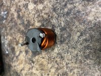
Will this affect anything with the core being broken like this ?
Attachments
Choke or Auto Trafo for Mains Voltage Reducing
- Power Supplies
- 6 Replies
I am looking for reducing mechanical hum of a big toroidal transformer (2000VA).
A DC-filter according
DC-Blocker - Scintilla-buizenversterkers
is already in use.
But in those cases where the mains voltage rises above 233-235VAC, suddenly annoying humming occurs again.
Using of a serial resistor is the wrong solution, but a choke with just the number of turns over which 5-10VAC drop (while at the same time the RDC value of the coil is so small that it can be neglected in order to the dynamic behavior of the associated power amp) should actually be a good approach.
Where I can order such inductor parts in a suited VA value above 2KVA ?
P.S.: An isolating transformator from 240VAC to 220-230VAC is the very best solution but too expensive due the necessary high VA-value.
Sourcing High quality toggle switches
- By tonescout
- Tubes / Valves
- 13 Replies
Hi,
I am going to run a bypass on my preamp to take out of circuit the balance and a stereo/mono selector.
Any ideas for a supplier of high quality toggle switches, this will take the signal?
Thanks
I am going to run a bypass on my preamp to take out of circuit the balance and a stereo/mono selector.
Any ideas for a supplier of high quality toggle switches, this will take the signal?
Thanks
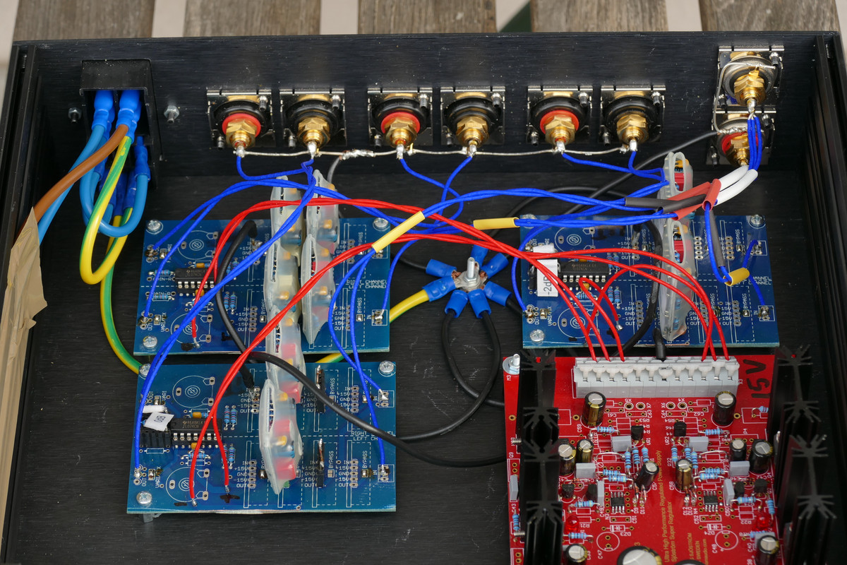
Bruno Putzey preamp current draw?
- By CentralCoast
- Analog Line Level
- 2 Replies
Any idea how much current the +12V and -12V rails draw on the preamp?
I have two pre amp boards. I am trying to decide to run them from silent switcher from diyaudiostore or from single pair of Hypex HPR12/HNR12
I have two pre amp boards. I am trying to decide to run them from silent switcher from diyaudiostore or from single pair of Hypex HPR12/HNR12
What about SSM3582?
Where is the buzz about this chip? I find it super interesting!
Info from the spec sheet:
"Digital input stereo, high efficiency Class-D amplifier
Operates from a single 4.5 V to 16 V supply
State-of-the-art, proprietary, filterless Σ-Δ modulation
106.5 dB signal-to-noise ratio
0.004% total harmonic distortion plus noise (THD + N)
at 5 W into 8 Ω
38.5 μV rms A weighted output noise"
I am dreaming about a super easy, cheap, low noise, cool running amp with direct connection to dsp!
Can someone please make a great layout for this?
Edit:
Oh, and I just have to coin this phrase: 5 watts ought to be enough for anyone!
Attachments
Power trans for eico hf 60
- By Elgordito
- Tubes / Valves
- 5 Replies
Any one know a good replacement power transformer for a eico hf 60, looking at some Hammonds but not sure which one to get. Open for suggestions
Hifonics with no + rail
BRZ1700
Hifoncs no + rail voltage
Rebuilt power supply, get square wave on gate and center pin on the 3205 fets plus on the output of the transformers..
12V IN 1.7 Amp
Put the negative rectifiers in and get around -55 volts. both sides
Put the positive rectifiers in and get nothing plus the power supply meter goes to zero amps but does not shut down or blow fuse.
I don't no where to look causing this, am assuming it has a short on the amp side of the circuit.
Any ideas?
Charging supercaps with LT1963
- By jimk04
- Power Supplies
- 2 Replies
Before we go on I am fully aware that these things must be respected. Potential bomb/fire/personal injury hazard if mistreated.
I have some 325F Maxwell caps that are paralleled and will be charged for 3v3 for various DAC psu rails....or atleast I am trying them out.
Tried initially with ebay purple LT3042 reg but the thing was burning up and would fault if the caps were empty as I guess they appear as dead short to the reg.
In the Ian Canada threads there are successful uses of his 3042/5 regs but they have a better ground plane for heatsinking.....as far as I am aware.
So I tried today with an ebay LT1963 and all went well. Reg chip got warm but not.so much to worry. The rectifier diodes got pretty toasty. Measured 360ma through them . I cant ID them so safe to swap those out for something beefier.
But my question sirs is do I need to isolate the charging reg from the supercaps when the charger is turned off.....otherwise won't the SCs discharge into the reg?
If this is the case I assume a relay is best for this but can diodes be used to prevent reverse 'flow'? Again I maybe assume thay the potential current would overwhelm the diodes?
Thanks for any advice. I do not go into this blindly and am taking no risks
Repositioning Rear Mounted Tone Controls
- By Crashbuilder
- Class D
- 0 Replies
Complete newbie ....
Just got a Dayton APA102BT amplifier and I’m toying with the idea of modifying it a bit. I want extend the rear mounted tone controls and place them on the front face plate. Would it be as simple as bypassing the rear potentiometers and possibly replacing them with some suitable linear taper potentiometers? Just prefer the idea of treble and bass knobs to device based equalizers apps. Any comments welcome.
Just got a Dayton APA102BT amplifier and I’m toying with the idea of modifying it a bit. I want extend the rear mounted tone controls and place them on the front face plate. Would it be as simple as bypassing the rear potentiometers and possibly replacing them with some suitable linear taper potentiometers? Just prefer the idea of treble and bass knobs to device based equalizers apps. Any comments welcome.
Y-Tech driver IC
- By Perry Babin
- Class D
- 1 Replies
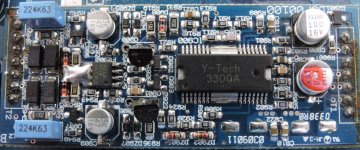
Does anyone recognize the Y-Tech driver IC on this board? I'm looking for any information on it. If it appears to be a re-badged IC, please post the part number for the IC it could be.
Thanks.
Thanks.
Attachments
Adcom GDA-600
- Swap Meet
- 0 Replies
90s DAC that I inherited. It may be in working order as it powers up, but I do not have a digital source to test it with.
$200 OBO


$200 OBO
PE Rex Deluxe alignment
- By morzh
- Analogue Source
- 2 Replies
I have finished my Grundig 8058 and am almost done with the record changer.
Almost, because I am trying to make the disks drop one at a time when the cycle is on.
I have just adjusted the height of the tonearm to the required 2-3/4" above the platter when it is raised; I am not sure about the spindle.
It does go up and down but either the record does not fall, or they all fall, or the tonearm is stuck and it takes manually turning the spindle a bit and then something clicks and the tonearm returns and tries to fall on the record.
The feeler works.
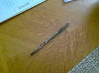
The spindle is in the photo
If the bottom small black cylinder that is used to pull the spring record holders down is pulled all the way, it feels that it clicks into that position.
I am not sure what it should be like. If someone knows please tell me. Including whether it is simply inserted in the center or it should be aligned in a certain way.
I am more of an electronics guy, and not really mechanical type. To some degree I can handle but this changer is really complex.
Almost, because I am trying to make the disks drop one at a time when the cycle is on.
I have just adjusted the height of the tonearm to the required 2-3/4" above the platter when it is raised; I am not sure about the spindle.
It does go up and down but either the record does not fall, or they all fall, or the tonearm is stuck and it takes manually turning the spindle a bit and then something clicks and the tonearm returns and tries to fall on the record.
The feeler works.
The spindle is in the photo
If the bottom small black cylinder that is used to pull the spring record holders down is pulled all the way, it feels that it clicks into that position.
I am not sure what it should be like. If someone knows please tell me. Including whether it is simply inserted in the center or it should be aligned in a certain way.
I am more of an electronics guy, and not really mechanical type. To some degree I can handle but this changer is really complex.
Attachments
I just noticed how low the sun is in the sky at 1:40pm EST
- By TheGimp
- The Lounge
- 2 Replies
Happy Winter Solstices day!
The days are getting longer and Spring is just around the corner. Well, three months away any way.
The days are getting longer and Spring is just around the corner. Well, three months away any way.
JL Audio 500/1 Rev10 Wont start up
Had one blown Z44 in PS and one blown 540 in the output.
Rebuilt PS and it is making 82vdc. when using my low amp 12v supply.
Have all 4 outputs in.
When I put it on my high amp 12v PS it tries to cycle on (pegs amp meter on supply then goes back to low draw again and again) but I don't think outputs are starting to switch.
I can read full rail on one speaker output and the other is at ground.
Question re Allen Wright PP-1cs
- By lilolee
- Tubes / Valves
- 65 Replies
I have a donor amp that can easilly become the PP-1.
However I'm a little confused by the B+ indicators
On the schematic there are two B+2 at the top and a B+3 on the anode of the lower ECC88.
Shouldn't the lower one be B+2 and the right B+2 at the top be B+3?
Cheers
However I'm a little confused by the B+ indicators
An externally hosted image should be here but it was not working when we last tested it.
An externally hosted image should be here but it was not working when we last tested it.
On the schematic there are two B+2 at the top and a B+3 on the anode of the lower ECC88.
Shouldn't the lower one be B+2 and the right B+2 at the top be B+3?
Cheers
FS: SCANSPEAK REVELATOR 15m4531k00 pair
SCANSPEAK REVELATOR 15m4531k00 (pair) lightly used in smoke free home and in perfect condition.Current price at Wilmslow Audio £370. My price is £240.incl delivery.UK sale only.
Arcam Alpha 10 intermittent protection mode
- By Dall78
- Solid State
- 6 Replies
Hi,
My Arcam Alpha 10 amp is going into protection mode sometimes (red flashing light) i can play it for hours sometimes with no problem and other times i switch it on and it goes into protection after playing music for sometimes 10 mins, 30mins etc, no exact timing to it. Any ideas/help on this matter would be great
My Arcam Alpha 10 amp is going into protection mode sometimes (red flashing light) i can play it for hours sometimes with no problem and other times i switch it on and it goes into protection after playing music for sometimes 10 mins, 30mins etc, no exact timing to it. Any ideas/help on this matter would be great
Tony builds himself a preamp.
- Tubes / Valves
- 0 Replies
In this Audiokarma thread i discuss and document the build of my new tube preamp.
A diy tube preamp, to set the bar. | Audiokarma Home Audio Stereo Discussion Forums
I wanted one thats really really nice for myself, and im using some of the best available stuff.
5691 tube feedback equalized riaa stage.
5692 cathode follower tape loops
Cinemag step up transformers for moving coil section
Simpson VU meters
Daven attenuator
Shunt regulated push pull output stage.
Dual mono power supply
Rack mounted.
Feel free to comment here or there. Ill be more likely to read your comments on Audiokarma
Low upload on cabled PC
- By richie00boy
- Everything Else
- 6 Replies
I've got a PC connected to the router by Cat5 cable and when I run an internet speed test it gives approx 30mb download but only about 0.1mb upload. There are two other computers on the same network, one wired and one wifi, both achieve same download but approx 8mb upload. So there is something wrong with the first computer.
I've tried a different socket on the router but it made no difference. What can throttle upload that I can look at?
I've tried a different socket on the router but it made no difference. What can throttle upload that I can look at?
Tekton is using up all the Beryllium!
- By eriksquires
- Multi-Way
- 87 Replies
Hi Guys,
I just thought you might like to see this extravagant use of the latest SB Acoustics Be tweeters.
Ulfberht Be - TektonDesign LLC
Actually, given the number of tweeters, I have to say this guy is getting a MAJOR discount from SB. I have no idea how it sounds, but I can't really stop laughing. Thoughts?
Best,
E
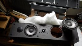
Bluetooth speaker retrofit
- By jlatenight
- Class D
- 21 Replies
Hi All, I hope I'm in the right forum. I got a Cambridge Soundworks Center channel speaker for free, and I thought it would be fun to make it a built-in stand-alone bluetooth speaker. Most of the chip amps I've seen have two channels, a left and a right speaker. This center channel has two midrange, apparently wired in series, and one tweeter and they connect to a crossover (I guess?). How do I wire the speakers to the 2-channel amp with one tweeter? Do I use the crossover somehow, or eliminate it? Any other advice you can give me? Thanks all!
Attachments
ParaSound HCA-1201A Schematic Needed
- By embrown057
- Solid State
- 5 Replies
I just acquired a Parasound HCA-1201A mono block amp that has a problem blowing fuses. So far I have found a few of the out puts shorted but could really use a schematic if anyone has one or service manual. There are a few resistors that got burnt also so I cannot identify them. So, I am stuck without the Schematic, any help finding one would be great.
Bias on Parasound HCA-806A
- By gto127
- Solid State
- 9 Replies
Having trouble finding a manual for this. Only wanted to set bias at this time. Anyone know the bias current for this as well as the measurement points?
Create single power supply from a supply
- By menno1000
- Power Supplies
- 14 Replies
Hi,
This question is the other way around. I have a +16-0- -16 power supply. In this lunchbox 0 is connected to ground. I want to make a discrete board with a 0v connected to ground and a positive rail of 30V.
Is there and easy way to do that? The goal is to create this eq board. A copy of a 1970 eq design.
Or can i feed this circuit without connecting the audio ground to zero?
Excuse my beginner level i display here..
Attachments

Kenwood Ka-7100 troubleshooting help
- By pjblakey
- Solid State
- 37 Replies
Hello guys,
I recently renewed all the electrolytic capacitors on the power amp section of a Ka-7100. Previously working fine, just thought I would recap it.
When I powered it up after recapping, the led light lit up briefly then the protection relay clicked in and remains stuck.
I triple checked all the new caps for polarity and checked all the voltages indicated in the service manual power amp board circuit diagram.
All voltage readings on the entire board are good except for the following:
Qe33 should be 14v, measures 1.9v
Qe34 should be .65v and 1.6v, measures .28v and 47v
RL1 should be 21v, measures 47v.
Re87/88 should read 18v, measures 1.3v
Pin15 should read 9v, measures 0v
There seems to be an error where pins 7 and 8 are reversed on the actual board.
When I installed the new caps, since the board was covered in a combination of grease and dust, I used denatured alcohol and compressed air to try and get the worst off. Maybe I shifted some crud to where it shouldn’t be?
Anyone able to assist in finding the source of the problem, I will be very grateful. I am challenged electrically, but am, or have been, pretty good and building amps and doing the mechanical stuff. This is the first time a project has not cranked up first time.
Cheers
Peter
Attachments
Hexateq chassis x3
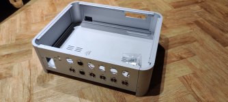
Having a clearout and I have these 3 anodised aluminium chassis.
Anyone interested? These are in the UK.
I'll strip all the internal stuff of value, but leave all external connectors.
Each one is 44w x 35d x 12/14.5h cm (external dimensions.
£120 for all three, plus postage.
Anyone interested? These are in the UK.
I'll strip all the internal stuff of value, but leave all external connectors.
Each one is 44w x 35d x 12/14.5h cm (external dimensions.
£120 for all three, plus postage.
Attachments
please help me understand english...
Hi friends
Still on the hunt for switches, I found an interesting one, but I'm not sure what exactly the term "Off-On repeating action circuitry" means. Does it mean that the switch works either way, and not turn-left = on, turn-right = off?
I'd then finally may have found if not the right switch then at least the term leading me to what I'm after... 🙄
The switch is this one here: "Carling R135-Series"
Thanks very much!
enjoy holidays, take care & stay healthy!
david
TF0410MR 900Hz Distortion
- By bourbon-neat
- Multi-Way
- 3 Replies
I'm building a MEH waveguide speaker with a Celestion TF0410MR midrange. While measuring the frequency response of the TF0410MR on the waveguide I noticed a 2nd order distortion peak @~900Hz. I measured the driver without the horn and the peak still existed. Both of the TF0410MR that I have show the same distortion peak. Is this normal for this driver? The power level is ~ .25 watt, measured at 1 meter.
Attachments
terminating VdH Revelation with...?
- By Le Basseur
- Parts
- 0 Replies
Hi,
Got these massive speaker cables (VdH Revelation Hybrid) and the mounted spades are in a pretty bad shape - very deformed (besides this,apparently,they're not the VdH originals) and badly/inconsistently soldered.
I'd like to replace these terminals with some quality spades/forks or even with bananas but I'm not sure what the overall wire Revelations' diameter and/or surface is on both the inner wires and shields used because I didn't yet cleaned the thermo tubing on the ends.And I wouldn't until I get the right terminations for it.
Another detail,crimped or soldered ?
TIA!
Hello from Boston area. Putting together a system...
- By Cstratton
- Introductions
- 6 Replies
Hi all. I am new to this forum. I joined to learn more about audio.
I am in the process of building an Elekit TU-8600s and wanted to have
access to any updates on the build from Victor at VK audio. I have also
picked up a Thorens TD-124 which will need some tweaking to get it closer
to its best performance. I have a tonearm on order from Alfred Bokrand
and which I will need to install and calibrate. Basically, I have "fallen down the hole" like the rest of you, if you get my meaning. Might ask some "stupid questions" so please be patient/kind....Thanks, Cliff
Heat Sinks
- By muskyhuntr
- Swap Meet
- 2 Replies
Item has sold!
My stash of heat sinks. Some new some old.
A list of what's in the stash.
2 pcs 10x2.5x1.25 (each has 3 holes taped for 4-40. 1 has broken tap in hole) Broken tap can be removed by immersion in a hot alum solution.
3 pcs 8.5x2.25x1.25 (1 has 3 holes taped for 4-40)
3 pcs 4.825x2.25x1.25 (2 have 2 holes tapped for 4-40)
1 pc 6x2.25x.5 (3 holes tapped for 4-40)
2 pcs 2.25x2x.5
1 pc 1.75x1.385x .75
37 pcs of various TO-220 board mounted sinks. Some tapped for 4-40.
5 pcs various clip on TO 220 sinks.
26 various sip sinks.
These are available as a package only.
$45.00 includes shipping. U.S. only. PayPal gift, family and friends.
Attachments
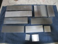
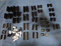
Simple PGA23xx Based Switching Preamp
- By vfxsoup
- Analog Line Level
- 4 Replies
Hi,
I'm waiting for my LM3886 power amp PCBs to come back from China so have decided to turn my attention to designing a "simple" preamp that can switch a few single-ended inputs and provide a digitally controlled volume. The idea is that it will drive the LM3886 power amp, or anything else I build in the future; I also want a line-level subwoofer-out for my REL Quake.
I like the look of the PGA23xx series chips for the volume control, and will probably go with either the 2310 or 2320 as they can use +/-12v rails (the only difference I can see is the THD values are slightly better on the 2320, and the 2310 is available in DIP).
Attached is the schematic. It's a work-in-progress, as I have some questions:
1) Are the buffers pre-and-post PGA required? I've not found a consensus about this on these forums, so I've included buffers in the schematic for now.
2) Is it worth adding some additional gain, and if so where is best - before or after the PGA? I', thinking it's probably not required as the PGA itself can go up to 31.5dB.
3) Should I be including filters before the PGA? There's a 2.2uF coupling cap and a low-pass filter for filtering out RF, but I also have these in the power amp circuits. The PGA datasheet doesn't mention anything about using a DC coupling cap at the inputs.
The front-end will be driven by a microcontroller, possibly an Arduino, probably an ESP32, as I can use its built-in wi-fi to drive a phone app or web app to remote control the input, volume, balance, etc. Physical controls will be a rotary encoder and some push buttons for input selection. I'm not too concerned with this at the moment because I'm a programmer so can get things like that working quite quickly. The electronics side of things is relatively new to me, and I'm learning as I go. The power for the digital and relays will probably be a 12v switching supply with a 5v regulator for the microcontroller and the digital side of the PGA; analog power will come from a regulated linear supply that I'll build myself.
Any feedback or suggestions greatly appreciated.
Thanks, Christian
Attachments
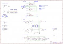
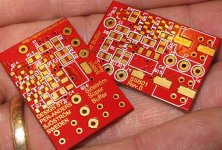
3 Inch Fullrange With Ribbon Tweeter Crossover
- By incredible80
- Multi-Way
- 2 Replies
Hi, I am currently building a small speaker for my bedroom, I have simulated a crossover for my build, but due to lack of experience, could not verify the design. Maybe someone would like to help me i designing a crossover for my project? Or maybe verify my crossover? Thanks!
P.S I attached the file for my drivers
P.S I attached the file for my drivers
Attachments
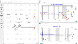
Korean half bridge amp strange issue
I have this 2k zenon amp here. It seems, it works fine..i have on each mosfets audio and ps a good signal. The amp needs about 7 amps to start,
then it idle at 3.3 amps.. If I use a power supply with only 5 amps, it won't power up fully, but all signals are there. Voltage drops at my bench supply to 7v..
With a bigger supply no problem. If I use a resistive load 4 ohm and inject 50hz,also everything looks fine. If I increase to clipping, or better to the fully 30amps from my bench supply,
The rail voltage breaks massive down. Even if I just touch the limit of my bench supply, the rail drops more then the half of voltage.. What could cause this?
Attachments
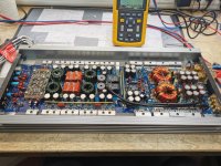
Load more
Projects by fanatics, for fanatics
Get answers and advice for everyone wanting to learn the art of audio.
Join the Community
507,757
Members
7,887,053
Messages