HSU PF-12100LPV 12" Subwoofer build plans

Some months back during the PE sale I got the HSU 12" subwoofer driver and then also got hold of HSU VTF-3 plate amplifier. Now planning to build a sealed sub only for the purpose of music and pairing with my Troels TQWT MKII speakers. Here is the link to the driver - HSU Research PF-12100LPV 12" Subwoofer

Was looking at some build plans either official HSU ones or diy ones which can do good for music. Any suggestions or pointers are welcome and I am first time builder of a sub by the way even though built different set of bookshelves or floor standers earlier including the Troels.

Thanks

The three blind mice - 3 triode LTP?

I've been playing with a front end from TubeCad: Cathode-Follower OTL and SIT FETs

Specifically this:
Single-Ended%20ECC99%2032-Ohm%20Headphone%20Amplifier.png


The front end is interesting, the first triode simply puts the signal out via the cathode based on the cathode for bias. The second triode amplifies for the output stage and takes feedback directly from the output - reduced by a 27K resistor. The interesting bit is that it then causes the cathode to bias and thus auto-bias the first triode. (actually input noise will also go up to the B+ via the first and then have anti-phase through the second and output stages).

So.. this got me thinking... Long Tailed Pairs and differential amps and how the auto biasing of the cathode could be used but in a unique way - using three triodes in the LTP.

Screenshot 2021-01-10 at 15.03.42.png

The first and last triodes provide the standard configuration, however a third (centre) triode is added simply to change the tied cathodes bias based on output feedback (rather than feeding into the grid of the second triode). This then almost replicates the original concept but for LTPs. Not new I suspect but still it seems to make it easier to manage negative feedback without messing with the phases.

Thoughts? (other than lunacy or why waste a triode)

FS- Audio Precision SYS-2722 192k

I'm selling my Audio Precision SYS-2722 192k and asking $9500 - insurance and shipping included within the continental US.
Local purchase and pick-up (Silicon Valley) will discount the cost of shipping.

Ready to plug and play, runs AP2700 v3.3 (free download at AP.com, no annual maintenance fees), manual is available as a free download at ap.com
  • APIB USB Adapter included
  • PSIA-2722 included but untested (I now have the correct cables, but haven't had time to test it)
  • Power, USB and two DB25 cables included
  • Rack mounts included for SYS-2722 and PSIA-2722

Loaded with optional modules and filters:
  • DSP And DIO Modules
  • IMD Option
  • BUR Option
  • WFA Option
  • AES17 LPF Option

This was AP's top of the line tester for many years
2700 Series Audio Analyzers - Audio Precision(C) | The Global Leader
"The typical THD+N of the 2700 Series is ≤ -115 dB at 2.0 Vrms. However, even with AP's conservatively specified THD+N of -112 dB, the 2700 Series is second only to the APx555 in analog performance."

Freshly calibrated (myself) on 17-Jul-2020 - all functions tested and working
Passes all performance self-tests, I posted the screen-capture video here (5 minute long test when sped up 4x): AP_Perf_test - YouTube

Thanks for looking!
-Olen

Attachments

  • IMG_9383.jpg
    IMG_9383.jpg
    749.5 KB · Views: 886
  • IMG_9384.jpg
    IMG_9384.jpg
    806.5 KB · Views: 867

Best desktop FR stereo for around 250$/€

Hello community 🙂 This place is a gold mine, thanks all sharers !

(skip at will) First post: introducing myself
The best system I ever heard is mine (having no friend that likes music as I do):
a Dynaudio Emit M20 stereo in a tile-floored living room with low ceiling... I come from far. 😱
Musical tastes: pop/Gregorian/classical/electro/rap... almost anything but jazz and heavy metal.
Spent hours reading much topics here and elsewhere.
Now I would gladly take straight input/answers as I progress too slow. Hence this new thread.
Current setup works great for couch-listening sessions,
but I spend hours on the computer and want good music there!

Blank sheet, with few constraints:

  • ~250$/€ for stereo speakers, including enclosure.
    Dayton RS100 drivers? Any a better option you like.
  • Computer as DSP / FIR / equalizer... no xo preferably.
  • ~80cm to listening point (2.6ft).
    bonus if system can fill the room, but not a goal.
  • Full range driver
    • to address phase/alignment problems
    • seems better on sound per bucks ratio considering computer DSP?
  • bass-ported if it's best (no objection on TL/open-baffle/horn though if it's basic plumbing/concrete/wood work)
  • angled drivers towards listener
  • <15cm (0.5ft.) wide enclosures, either placed on table or on the floor.
  • <120cm high (4ft i.e. 35cm above desktop)
  • <55cm deep if on floor (1.8 ft.)
  • Sub-woofer ruled-out since I fear they grow people deaf
  • Non-fatiguing sound: daylong listening
  • non-pervasive looks
    (I won't spend time on finishing though)
My constraints might be as dumb as I: if one seems plain wrong to you, please teach me.

There might be an obvious solution: please spell it out: I found and analyzed many nice projects but can't spot an obvious way to go.

With DIY, I hope to outperform identified commercial solutions:
dali spektor 1 / EVE audio SC203...

Thanks for reading me this far!

Wireless protocol for audio, other than Bluetooth?

My question seems simple enough at first glance, but I'm having a hell of a time thinking of a solution.

My mother and father are both very elderly. My mother, despite her age, is very spry and still very much "with it." My Dad has dementia, and has begun to exhibit some... very strange... behavior. One of the things that he's started doing, is he wants to keep the television volume extremely low. I've witnessed this, and he really does insist on having it just low enough to be extremely annoying to anyone who is in the room trying to watch too. So... my mother, thinking that her "tech savvy son" (i.e. me) can usually fix every situation that involves gadgets... she asked me if I could make her a tiny speaker that she can have sitting right beside her, with a volume knob, so when my dad turns the tv down super low, she can kind of ease the volume up on "her speaker" so she can still hear.

Here are the parameters that make finding a solution more difficult than you might think.
  • She does not want it to be headphones. Absolute no-go.
  • Can't have a cable going across the floor. Their living room is enormous.
  • It must be wireless, but it can't be something she has to "pair" or do anything technical.

I bought her a Bose sound bar for Christmas, thinking that might be the ticket. With there being 1 remote for the TV, one remote for the Bose speaker, and another for the cable... even though it did not pair up with any kind of bluetooth... I knew right then and there that there is no way I'd ever be able to get her to figure out Bluetooth. Plus... I may be mistaken, but... I believe that any kind of Bluetooth device that pairs with a Television, takes over the audio all together, and the television's native speakers shut off. That would mute the TV for my Dad across the room, and only my mom could hear.

Such a crazy issue. Anyone got any ideas?

Thanks everybody!

Kit recommendations – efficient speakers

I'll be building myself a pair of The-Loudspeaker-III designed by Troels Gravesen in the near future.

It's an efficient set of speakers, rated at 92db, and it requires 15W per channel. The subwoofer part is active, powered by an Hypex FA251, and fed from the crossover.

I'm wondering if going down the tube amp road is worthwile. I figured that, as it doesn't require a lot of power, it might just be possible to build a nice, quality tube amp for them. Any recommendations or any pointers would be really welcome!

Linn Axis Power Supply:No Slowdown

Hello to all, first post, great Forum!

I'm using a Linn Axis power supply in a remote enclosure to drive my LP12.

The Axis supply was a bit of a "stretcher case" when I first got it, but several BUX85's and op amps later, the supply is now running at both speeds.

The output transistors are getting pretty hot though, and I noticed that the reduction of the motor volts, once up to speed, isn't happening. I still have 76v (?) to both windings with no variation.

Anyone able to point me in the right direction?

This is a swine of a circuit to get going, but I'm so close to success now, maybe someone had already been here?

I have a copy of the circuit diagram.

Thanks in advance.

Dual Mono DAC AK4490/AK4497

This thread is to initialize a new board and finished DAC based on a prototype build from base board from DIYINHK , idea behind is to get best quality and performance based on XMOS, AKM and NDK product.

My prototype based on AK4490 and XMOS isolated from diyinhk build my motivation to build first a dual mono AK4490 with ultra low noise supply and low jitter clock to reach the best performance of this nice and powerfull DAC chip interfaced with the XMOS Xcore-200 to have enought control and power (MIPS) to cover the need to reach the PCM 32bits 768khz and DSD 256 (native or DoP). Then an other board based on the new AK4497 when i get sample in February before mass production of this chip between April and May 2016 (seems to be officaly for summer 2016).

Some SPEC

For AK4490 32bit Stereo DAC:
S/N : 123db (in mono mode)
THD+N : -112db
PCM: up to 768khz
DSD: up to DSD256

For AK4497 32bit Stereo DAC
S/N : 131db (in mono mode)
THD+N : -116db
PCM: up to 768khz
DSD: up to DSD512

For oscillator part i select NDK but we will see if better solution could be proposed from our Diyer there.
I have already asked NDK for getting sample from the new Duculon product but first is this to expensive (arround 1600€ pcs) could be used only for public where a high end product for this type of over killed quality and price as no impact 😉 (DAC cost could be estimate arround 6K€)

Let go first to the first step the optimal choice in a reasonable price.

Before building a new PCB i will create with you the prototype by using DIYINHK product , we will proceed on some fine tuning and customization to get our target runing and be distributed or self builded.

After we will search a good way to build a nice litle PCB for and his boxed version.

Then one other PCB for the Premium last new AK4497 with his very good performance and quality.

This thread is to exchange experience and build a DAC together on a reasonable and performance way, and is not a commercial activities. I will give you the current state of my current experiences what is already done, what is currently in task list and what is to be planned.

When you have any question please ask me now on this thread before i begin any step to get it working (i tell you the current sound going out is amazing)

Enjoy to exchange your experience into this thread , thanks in advance all for your input 😉

Cal1sto

AK4479 or AK4499 DAC Kit????????

My home system is Parasound A21 driving Thiel 3.6. These match well but I do not like my Buffalo IIISE with them (no preamp). The Sabre chip just seems too harsh.

I have a DIYINHK AK4497 DAC that I built and it sounds good but it is not easy to get it to work with the DIYINHK XMOS USB to I2s converter and my Android tablet. I run TIDAL off the tablet.

I am looking for an AK4497 or AK4499 dac I would be happy with either of the following:

1. A complete kit that can be built without extensive audio electronics knowledge. I can read instructions and I can solder. I like kits where a build has been documented online with many pictures.

2. A good ebay or alibaba chinese board that has been proven as a quality product. The following may be one of those: Dual AK4497 AK4497EQ DAC DSD HiFi Decoder audio +Bluetooth 5.0+Amanero USB NEW | eBay or 2019 Dual AK4497EQ DAC AK4118 AK4497 DSD256 Native DAC 32Bit 384KHz USB AK4497 DAC,XMOS XU208 Amanero USB Bluetooth 5.0 APTX HD-in Amplifier from Consumer Electronics on AliExpress


Any help would be appreciated.

Improving an old power amp

I have this old stereo power amp (early 1980's) that has been sitting unused for 10+ years that I want to put back into service. It was the first commercial product of a well-respected designer who was a friend of mine and who shall remain nameless (at least for now).

I see some "systemic" things that bother me, but I am no expert at discrete design. So, while I have it disassembled, I'd like to get some input on how to improve it. I have attached scans of the only available info for it: amp channel, power supplies, and parts list. Note some error corrections in red on the parts list.

Right now both channels work but have 250-350mV of DC offset after warmup. So far I have:
: replaced all the 'lytics and carbon comp resistors, some of which had gone well out of tolerance.
: verified all the power resistors ( > 1/2W ) are good.
: Matched the 1k2 R's to the input pair within 1 Ohm.

I'm also adding a dual 10k pot at the input.

My amp mostly matches the schematic but not exactly. On mine, Q1 and Q2 are 2N5651's. There is no trim pot between Q5 base and emitter. C5 is 100nF. At the inputs, the 2R2 is 2R7 on mine. C12-C15 in the ps are now diodes (correctly oriented). (There may be other differences I haven't noticed)

Things that bother me that I will be addressing:
: some ps distribution asymmetry in the layout.
: very little capacitance on the regulator adjust pins and outputs.

and then
: standing the channel grounds off power ground by 2R7 (why?)
: gain is much higher than needed

Without altering the basic design (space is limited on the pcb), what would you do to improve it?

Attachments

  • PS2amp1.jpg
    PS2amp1.jpg
    502.2 KB · Views: 398
  • PS2ps.jpg
    PS2ps.jpg
    347.7 KB · Views: 406
  • PS2pl.jpg
    PS2pl.jpg
    218.6 KB · Views: 402

MUSES 72323

Hi!
While researching a bit on the Muses Volume, I found there's the Muses 72320 as well as the newer 72323... but this newer thing doesn't seem to be mentioned here at diyaudio...
Is there a reason (like, too far out for diy 😀 ?)

btw, I got myself a Muses volume Kit from meldano, thus will dig into muses (AND SMD) sooner than later anyway...

david

Marantz DR6050 as an external DAC ?

Hi guys
I have the Marantz DR6050 - CD Recorder and I have two questions.

1. Can I use it as external DAC? It has digital optical and coaxial inputs. I want to put digital signal from the PC.

2. Sometimes its display freezes and the sound is dropped. I found a service bulletin that says: "Solution: Replace the DASP IC <IC 7701> with the improved version."

Where can this IC be purchased

Every aid will be appreciated.

Greetings!

Attachments

LINN Axis Turntable Motor

Need help on the Linn Axis Pully Motor:
Initially I found that the motor has a hard time starting up. Even with turning the platter by hand, it only revolves a short time and is slow on 33rpm, then stops and little to none on the 45rpm speed.

I have replace ALL electrolytics caps, replaced the R1 resistor with an uipgraded thermistor and the rectifier also upgraded, new drive belt and re-oiled the subplatter well as recommended by a Linn service person.

Still the platter does not rotate freely and eventually stops. The motor has a vibratory noise and sometimes starts backward.

Is the motor shot or some other parts needs replacing. Please help. Thank you
Tony

Question about sand-filled CLD woofer cabinet

Hello,
I'm about 85% through with this woofer build, so for better or worse,
the design won't be changing by a great deal.
I think it should work at least "OK".
It is essentially like a Linkwitz Thor, except two boxes (stereo bass).
The old 12" Peerless XLS in a sealed box, around 1.2 Cubic feet or so.
I'll be using a Marchand Bassis for bass EQ.


So.....


I'm building a box-within-a-box, each box is 3/4-in MDF, the space
between is about 5/8-in on 5 sides (4 sides and the back).
The damping layer will be heavy sand, Chromite sand.


Finally, here is my question:
Should I coat the MDF surface on the inside of the outer box and
the outside of the inner box with an epoxy sealer ?


This would be in theory an anti-abrasive surface for the sand, since
I don't know how much the vibrating sand might etch the wood
over time.


Thank you for your thoughts !

new to response measuring! mic and software recomendations please

hello everyone.

I've recently finished my first couple of speaker designs. I'm happy with the results but I would really like to progress on to taking frequency response measurements. to test old speaker as well as new drivers for crossover design. basically just wondering what software and microphones people would recommend. happy to spend a bit of money as its Christmas time!

Overview Impedance Plots wanted for Infinity to avoid destroyed Amps (e.g. RS/Kappa)

There are several models on the marked with passive high pass crossover network for the bass transducer. Consequence is an enhancement of the bass transmission (only a small area around 40-50Hz so as acoustical low pass character of 24db/octave instead 12db/octave)
Additional the impedance goes in this area down below 1 ohms at several models. This means danger for destroy amplifier stages.
Therefore I want to have a line up of all associate impedance plots and crossover network circuits to older Infinity multi way speakers.
On the web there are only any few plots - go to the attachments.

Many thanks for the progress of the completion.

in post #43+44 under
Infinity 8 Kappa Rescue Project
there is to find an approach from me as general solution for models with minimum impedance below 3 ohms.

Except the Kappa (Reference Standard) series there are several other series, e.g. IRS-Sigma/Epsilon - go to
INFINITY IRS SIGMA TECHNICAL SHEET Service Manual download, schematics, eeprom, repair info for electronics experts
An overall view of all models is here:
Infinity Modelle

Attachments

  • Infinity Kappa 9A.jpg
    Infinity Kappa 9A.jpg
    82.1 KB · Views: 599
  • Infinity RS-5000.jpg
    Infinity RS-5000.jpg
    107.2 KB · Views: 292
  • Infinity R352.png
    Infinity R352.png
    83.3 KB · Views: 211
  • Infinity PRIMUS 360.jpg
    Infinity PRIMUS 360.jpg
    27.5 KB · Views: 435
  • Infinity kappa-8.2 impedance vs. frequency.png
    Infinity kappa-8.2 impedance vs. frequency.png
    69.4 KB · Views: 629
  • Infinity kappa-9.2-extend-on.png
    Infinity kappa-9.2-extend-on.png
    65.6 KB · Views: 887
  • Infinity Primus P363.jpg
    Infinity Primus P363.jpg
    168.5 KB · Views: 283
  • Infinity kappa-9.2-extend-off.png
    Infinity kappa-9.2-extend-off.png
    65.1 KB · Views: 341
  • infinity_irs_sigma_technical_sheet.pdf
    infinity_irs_sigma_technical_sheet.pdf
    143.1 KB · Views: 118

Low Pass Filter Modification

I have this board with several frequency filters.
The one I am wanting to modify is this one.
What my intention is to bring the trigger (center) frequency down to about 50 to 75Hz, from the current 300Hz.


I don't have Spice or any of those apps, but could someone look at this circuit, perhaps suggest what part values to change for the modification.
Thanks in advance.

Attachments

  • low pass filter4.jpg
    low pass filter4.jpg
    84.4 KB · Views: 122

HANA-EH HANA-EL HANA-SH HANA-SL (new Phono Cartridges)

A friend have purchased the model "SL" and sonic quality is very good, but a bit to crispy.
Here several URL's concerning the company and short form data:
HANA | Youtek.com
Osage Audio Products, LLC
Hana S-Serie
from this cartridges I have never heard before and seems to be released at spring 2018 - go to
https://web.archive.org/web/20191105000114/http://www.youtek.jp/pdf/manual/manual_hana_2017s.pdf
according the review from Germans magazine "Stereoplay" - go to the attached PDF - I note an enhancing in the frequency response of around 6db/octave between 10KHz and 20KHz.
What values are necessary for the load (resistor, maybe even an actually unusual capacitor) for getting a flat response.
Thank you very much.

P.S.: under
Happy Birthday to Me - A New Hana Cartridge
(compare to the AT-OC9) there isn't to find the wanted information.

Attachments

LTSpice model of BHL MC head amp...no output

I modeled the Boozhound Labs moving coil head amp using the LSK170 model that comes with the latest distribution of LTSpice (add njf, place > pick new JFET, choose LSK170). I didn't define anything past that.

With 0.3mV in, I get no signal past the drain. There are no open lines.
18VDC voltage supply.
Do you see any errors?
Any possible missed steps?

This is my first solid state circuit simulation. I usually work with tubes.

Thank you for your input.

Adam

Attachments

  • BHL MC LTspice.JPG
    BHL MC LTspice.JPG
    42.5 KB · Views: 96
  • BHL MC LTspice voltage.JPG
    BHL MC LTspice voltage.JPG
    213.6 KB · Views: 88
  • BHL MC head amp schematic.JPG
    BHL MC head amp schematic.JPG
    51.1 KB · Views: 98

How to test germanium output transistors

I picked up a Teisco Checkmate 20 amp and promptly ruined it.... The reverb was not working, so I decided to feed a signal to the output of the spring tank to see if the recovery circuit was working. It worked fine,(roughly have the original signal strength) so I figured that the tank was bad.
With the signal feeding into the tank output, i had the bright idea to feed the audio signal from the tank input,(output from preamp) back into the main instrument input, to see if the reverb input circuit was working.
The amp promptly oscillated, and blew a fuse. It will blow a fuse immediately if the output transistors are connected. Without them, the tremolo light flashes normally, and voltages seem sane.
I don't have any experience with germanium parts, and the datasheets I find online are vague on pinout, or else I just missed the boat. Usually the case....
Any guidance would be fantastic.
Transistors are 2SB407 Sanyo

Thanks in advance!

39c1611207ffbae4dfa4fbe6e569affe.jpg


b1348e19985b59ea3cc925bc219ac8a6.jpg
3da6b8d8e1332744b9f6f06c70a26dd9.jpg


Sent from my SAMSUNG-SM-G900A using Tapatalk

5v signal splitter for elec guitar (or other instrument)

Greetings,


I am new to this site and DIY electronics in general so please be gentle.


I need to split the input from an electric instrument into 2 outputs to effectively send down 2 effects channels and finally to 2 separate amplifiers. I found a schematic (attached) which I think does what I want to do. However, I only have 5v to play with and the TL074 seems to require 6 minimum and I suspect that is +/-6.


All I have to work with is +5v, Ground, and the instrument input. I think I know how to create +/-2.5 from the 5v.


So my questions are:


  1. Is there a good op amp that will operate at +/- 2.5?
  2. If I remove the "Loop Through" from the schematic, replace the TC074 with something that runs +/-2.5v will this work?
  3. Am I correct in assuming that if I put +5 on the v+ and ground on the v- I am effectively getting +/-2.5?
I feel like the 'nowhere man': "Ad hoc, ad hoc, quid pro quo, so little time, so much to know"


Thank you for any assistance.

Attachments

  • Splitter.gif
    Splitter.gif
    69.9 KB · Views: 1,483

Asymmetric Satellite Sub woofer System

Asymmetric speaker system.

Satellite subwoofer systems are an effective solution to the problem of reproducing the bass frequencies in a speaker system without using the space that the more common two speaker system uses.

Having built a satellite subwoofer system in the past, I was able to appreciate the decent performance afforded by even a rudimentary system, however the placement of the subwoofer on the floor proved problematic.

One solution I have been looking at is the placement of the subwoofer adjacent to or inside the enclosure of the satellite speaker, either in a forward firing position as shown in the 3D graphic here or as a sideways firing driver, since directionality is less important for the lower frequencies.

assymetric2.jpg

What are the possible problems that could occur in such a system, and also what sort of dummy load is to be used if only one subwoofer driver is to be used - for example attached to the left speaker which will have an impedance of 8 Ohms for example?

Some info here, but I have not found answers yet to my questions.

All You Wanted To Know About Subwoofers

Overview of 2.1 (Satellite/Subwoofer) Spe - Maxim Integrated

B&W Nautilus tapered transmission line for full range driver?

I'm taking my first journey into single driver full range sound using a Wavecor FR090WA02 3-1/2" Aluminum Cone Full-Range 8 Ohm driver and I had the thought of putting it in a Nautilus like TL tube. I guess technically my system will be full range and sub as I will be using a subwoofer below 150hz or so but I am really wanting to use the Wavecor FR as I have them on hand and they sound very good in a traditional closed box. I'm using a MiniDSP 2X4 for crossover and EQ purposes with circa 45 watts to the FR.

Has anyone tried to copy the B&W tube and if so how did it go? Also, can I use a standard TL calculator to design the TL tubes or is this type of enclosure actually a compression line of some kind?

Thanks for any replies.

Attachments

Alpair 7.3eN/12pw WAW build

I’ve been enjoying my homebrew WAW speakers for a couple of years. When I built them I knew absolutely nothing about speaker design so I looked around for a design I could copy. Omega speakers had a good reputation, so I made a version of one of his Outlaw speakers using a Fostex F120a and a Dayton 8” sub. It sounded good enough that I was satisfied for a while but, reliable as the sunrise, the itch for something better soon reared its expensive head so I started a thread:

Am I getting the most from my Fostex F120a WAW?

The short answer to my question was yes.

And no.

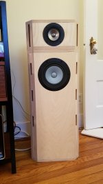
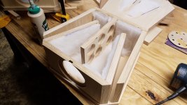
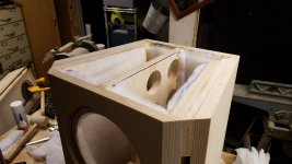
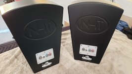
Lots of reading and advice later, I realized that I still didn’t know a thing about speaker design so I decided to try one of the Planet 10 designs using Mark Audio drivers. Dave was incredibly patient and generous with his knowledge, both on the thread and in 50-odd emails during the build process. This weekend I finished gluing up the cabinets, installed the drivers and…..wow.

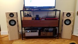
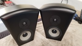
The cabinets aren’t veneered yet, and the drivers still have some breaking in to do, but these are already in an entirely different league from my previous speakers. So much more dynamic, with absolutely no shout. The bass I was so concerned about is there in profusion. I really didn’t think the 12pw would compare to the Dayton sub and I was right, but in the wrong way. There is so much bass that I may have to plug up a vent or two to settle it down. I’ll play with positioning and give them more time to break in first, but this driver/enclosure combination defies imagination. They are also MUCH faster than the Daytons. I had the 7.3 enclosures done a week or so ago and, paired with them, the Dayton sounded geologically slow. The speed and extended range of the 12pw, on the other hand, matches beautifully with the 7.3. Almost like they were meant to work together…..hmm.

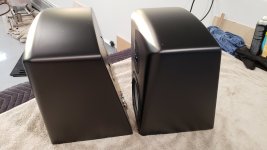
The woodwork is far from perfect, but I don’t think my mistakes have any effect on the sound. They were time consuming but not especially difficult to make, though I will admit that my newly-acquired track saw made it infinitely easier than it would have been using my contractor-grade table saw. Safer too.

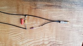
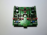
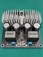
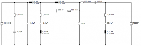
I also made some PLLXOs as part of this project. They were done a few weeks ago and made a HUGE difference from the start, even with the old speakers. With the new drivers I can really hear the extended range of the 12pw. The midrange is filled out more completely, without a discernable gap in the handoff from one driver to the other.


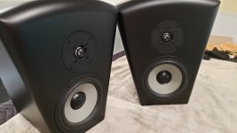
Now to select the veneer, and decide whether I’m going to do the sides in black (think Devore O/96) or veneer them the same as the front baffle.

Attachments

  • 20180217_150828.jpg
    20180217_150828.jpg
    345.4 KB · Views: 2,464
  • 20180217_150837.jpg
    20180217_150837.jpg
    654.6 KB · Views: 2,356
  • 20180206_232112.jpg
    20180206_232112.jpg
    682 KB · Views: 2,063
  • 20180216_220216.jpg
    20180216_220216.jpg
    517.9 KB · Views: 2,023
  • 20180204_121040.jpg
    20180204_121040.jpg
    1,020.5 KB · Views: 2,036

Cyrus 2 power supply capacitors replacement

Hi All,


I have a Cyrus 2 (rev 7), I'm looking for a good quality power supply capacitors to replace the 2 Elna 10,000uF 50V capacitors (there is a small dent on one of them).
I'm not looking for a very expensive replacement, just a good one that can be found in the UK for around 10-15GBP/cap.


Does anyone have any experience with DNM "guided current" capacitors?


Thanks

Are my Chinese 2SA970 and 2SC2240s really low noise?

To fix a Marantz amp I needed high voltage low noise transistors. I could use the standard 2N5401/5551 transistors but they're not exactly appreciated for their noise performance. To put this to the test I built a simple test jig. It emulates a noise figure meter, only it's not calibrated so I can only do comparisons. But that's OK. The jig (schematic on its way) has an input for a reference signal (10 kHz), an attenuator, the socket for the DUT (Device Under Test) and an opamp. The output goes to a spectrum analyzer, although a scope should be possible too.

With the analyzer I can look down to almost DC. A transistor has 1/f noise, which on my analyzer (0-10 MHz) peaks at around 2 kHz. Hence the 10 kHz reference frequency. After all, I must compensate for the amplification of the DUT. So, with my Chinese loot having arrived, I did the tests with six types, 2SA970, BC560C, 2N5401 (PNP) and 2SC2240, BC550C and 2N5551 (NPN). The results are the difference betwen the arbitrary reference signal level and the noise level for my analyzer's bandwidth:
DUT Noise [dBm] Ref [dBm] diff [dB]
2SA970#1 -41 -30 11
2SA970#2 -41 -30 11
BC560C -38 -29 9
2N5401 -39 -35 4
2SC2240 -38 -27 11
BC550C -38 -24 14
2N5551 -38 -29 9

Apologies for the crap formatting but I can't seem to be able to use HTML code... Anyway, the difference means the higher the better. These results are consistent with my expectations and the Chinese transistors are indeed low noise. Now I have to test whether they're also high voltage...

Oh, the amp (PM80 Mkii) just suffered from dry joints.

Orion xtr5004

I am working on an Orion xtr5004 and I have run into a wall and need a little help. I have rebuilt the power supply and with the rectifiers out it powered up just fine. I have removed all the output fets which are irl540n's. When I put rectifiers in the amp cycles in and out of protection. If I remove the voltage regulator ics it powers up and works great, Even with the rectifiers in. I replaced the lm337 and the lm317 but with them in the amp goes into protection. I replaced both 100ohm resistors that feed the v regs as well. Does anyone have any thoughts about what could be my problem?

Skar Audio RP-75.4ab

Amp will not power up

Here is what I get on the 494

Pin 1:0.00
Pin 2:0.00
Pin 3:0.00
Pin 4:0.00
Pin 5:0.00
Pin 6:0.00
Pin 7:0.00
Pin 8:13.94
Pin 9:0.00
Pin 10:0.00
Pin 11:13.94
Pin 12:0.00
Pin 13:0.00
Pin 14:0.00
Pin 15:0.00
Pin 16:0.00

Any ideas ?

Attachments

  • DCAA6769-67CB-47E1-AA9D-A44F2566F812.jpg
    DCAA6769-67CB-47E1-AA9D-A44F2566F812.jpg
    977.7 KB · Views: 64
  • 2DB819AD-AACD-4D53-8961-E2D97022FEFA.jpg
    2DB819AD-AACD-4D53-8961-E2D97022FEFA.jpg
    1 MB · Views: 68
  • 2F0D072D-A0BB-46E2-BBF2-18B9204E3CDB.jpg
    2F0D072D-A0BB-46E2-BBF2-18B9204E3CDB.jpg
    1.1 MB · Views: 69

JBL 2279H data

Hello,

I cannot find much data on this driver

does anyone have any measurements?

Its very cheap here:
JBL 5048239X 2279H Low Frequency Driver for SRX828S - Speaker Exchange

I can get the distortion data at 115db/1m for the 2268 driver (possibly similar?)
https://jblpro.com/en-US/site_elements/tech-note-jbl-s-differential-drive-transducers

Which gives a peak of about -38db for the 2nd harmonic, but its at 115db/1m, so I cannot compare it easily to my data of the AE TD12m at 100db at -55db for 3rd harmonic

AE Speakers TD12M - drivervault

Any suggestions on comparable distortion?

Use case is:
Cabinet volume unlimited.
max SPL about 110db ish?


td10/td12m would be used between 200hz and 620hz, with a 2242 (or the 2279) below that,

or

run a 2242 or 2279 from 25hz-620.

Alternatively, another driver entirely of your suggestion, but it must be good value, so either available second hand or just well priced.

Thanks.

Elekit tu-8600 Problem

The Voltage Amplification tubes (1st stage - 12AX7 + parallel drive 12AU7) in my amp jump really bright when first turning on the amp. A second later they are dim and appear normal.

Is this a Normal operation of this amp?

It also is much quieter out of the left channel. Obviously this part is not normal. I have a spare set of tubes to install here but before possibly damaging them, I want to see if there is something else wrong.

Thanks!

Attachments

  • 761F5688-A280-4378-B889-01AEA1F34E5D.png
    761F5688-A280-4378-B889-01AEA1F34E5D.png
    800.8 KB · Views: 262
  • 494DCFB0-986D-459E-A26C-5E4BD24570F1.jpeg
    494DCFB0-986D-459E-A26C-5E4BD24570F1.jpeg
    59.7 KB · Views: 262

AR P315 subwoofer schematic

Looking for a schematic for the Acoustic Research P315HO speaker system. The amp is marked Recoton Home Audio subwoofer amp. Audiovox, AR and Recoton haven't been any help.
I found two transistors shorted in the subwoofer amp, a 2SC3281 and an IRF640. I replaced them but there is still a large dc offset in the output, about 10.5 volts. Without a schematic I'm kind of just fishing.

Lanzar EV1804D

Good day folks,
I got this Lazar EV1804D, came in in protect.

It seems to have previous work done on it. I repaired the PS and got that up, (114vdc rails, +/-15v, and +5V). I don't have any oscillation on the output FETs, all output FETs (IRFB4227) are out of the circuit.

The class D card is a 13 pin version and is fully encapsulated in a black epoxy. I haven't come across this 13pin variant of the class D card.

Below are some pin voltages, and what I traced for the 13 pin card (left to right ref to center tap sec transformer)

1: +15v
2: 1.59 vdc (spk out)
3: 1.51v
4: audio in
5: +5v
6: 6 mv (gnd/center tap of transformer sec.)
7: -15v
8: -58v
9: 1.58v (gate drive)
10: -44v
11: +58v
12: 1.58v (gate drive)
13: -58v

Anyone worked with this amplifier/driver card before and willing to assist?

Attachments

  • IMG_0588.jpg
    IMG_0588.jpg
    980.6 KB · Views: 79
  • IMG_0587.jpg
    IMG_0587.jpg
    1,019.4 KB · Views: 98
  • IMG_0726.jpg
    IMG_0726.jpg
    779 KB · Views: 71
  • IMG_0727.jpg
    IMG_0727.jpg
    671.7 KB · Views: 62

Dearmond Pilot V5 Bass Guitar

Hello to you all. May this year be a happy and productive musical year.
I tried on another forum but no luck.
So I come back to DIY and have a try here.

A Dearmond Pilot V5 came in for repair.
The electronics have been removed, connectors snapped and an attempt is made to change it to a passive bass.
Finally it landed on my bench.

I attached a file of the pcb with the burned part.
The wiring diagram is available but it's the electronic schematic I need.
If unavailable, a picture of the pcb, front and rear, would help me a lot to repair that part.
If anyone could provide me with a close up picture of the burned pcb part, I will be very happy.

Thank you very much.
Cheers,

Attachments

  • 200108 Pilot V5  Burned pcb 1.jpg
    200108 Pilot V5 Burned pcb 1.jpg
    471.1 KB · Views: 101

ICEPOWER 1200AS2 Small GB Needed

Looking for a few people interested in the Icepower 1200 AS2. We have a couple of confirmations now but need just a few more. The price would be 425+ shipping from MN each. They come in lots of 7 so if anyone interested come on board. I have found fully fleshed out enclosures to complete from Ghent audio. I'll try to link. Also try to attach the datasheet for the 1200.

https://icepower.dk/support/#download-expand

ghentaudio --- DIY Stereo Case for ICEpower 1200AS/700AS

Supplied links, datasheets were too big

Question about the separate power supply of the AD1865

Hi, I'm building a dac with AD1865 (a clone of the note audio), with the cs8414 receiver, both chips have both analog and digital power, and I was wondering: how useful would it be to separate the power supplies of the two chips? Making an analog and digital power supply for the dac, and one also for the receiver, so as to have a total of 4 power supplies, 2 each chip. All power supplies are further filtered with the tl431. Like this scheme.

Tiziano

Attachments

  • DAC-END-cricuit.jpg
    DAC-END-cricuit.jpg
    338.1 KB · Views: 107

  • Locked
FS: NHT M60 2-way speakers

Used NHT M60 2-way professional monitors. These were intended to be used with NHT's XdA preamp/dsp/amp and require a subwoofer for full range bass. They have no cross-overs. Despite what the box says, they are not powered monitors. You'll need to use a digital cross-over and external amplification. There have been discussions on forums about building traditional cross-overs for these with example schematics. They contain a 6" Seas woofer and 1" dome tweeter. I have 4 pairs for sale. 3 pair all original and 1 pair with similar Dayton Audio dome tweeters. At one time I used these in a 7.1 HT setup. Been sitting in their boxes for about 18 months. Time to clean out my storage. $150/pair OBO plus shipping from CA. Each box weighs 22lbs. Local pickup possible.

Attachments

  • 20200725_194444.jpg
    20200725_194444.jpg
    345.7 KB · Views: 320
  • 20200725_194500.jpg
    20200725_194500.jpg
    317.1 KB · Views: 319
  • 20200725_194511.jpg
    20200725_194511.jpg
    340.1 KB · Views: 316
  • 20200725_194543.jpg
    20200725_194543.jpg
    267.4 KB · Views: 323
  • 20200809_132523.jpg
    20200809_132523.jpg
    251.6 KB · Views: 315

MJR-7 Mosfet Amplifier of M. Renardson

Hi,

I would like to test the MOSFET amplifier designed by M. Renardson, from
http://www.angelfire.com/ab3/mjramp/amp7.html.
http://www.angelfire.com/ab3/mjramp/construct.html
http://www.angelfire.com/ab3/mjramp/simple5.html

Did anybody experiment with it? How does it sound?

I would like to ask some advice regarding the implications of increasing the voltage from 60V to 90V and eventually adding a second pair of MOSFETS for extra output power.

Besides choosing capacitors of higher voltage for the power supply and for the 4700uF output (100V instead of 63V), do we also need to increase the output capacitor from 4700uF to 6800uf or higher in order to accomodate the extra power?

If we increase the value of the output capacitor, since it is part of the feedback loop, do we also need to adjust the values of any other components ?

Do we need to increase the value of the power supply capacitors from 12000uf to let say 20000uf?

To add a second pair of MOSFETS, I assume that I would need to add another pair of resistors (330R) and 12V zener diodes to drive these MOSFETS. Is this correct?

Any other advice is welcome 🙂

Thanks!

Attachments

  • amp7.gif
    amp7.gif
    11.1 KB · Views: 2,332

Cats & speaker grills...they don't go together.

I have a pair of WTW towers I built some 20+ years ago, a girlfriend at the time got "us" a cat...it didn't take long for the cat to destroy the pair. The woodwork of those towers has since morphed into a reimagined Infinity Qb, tall & sleek.
Fast forward to today, the towers are in another room, now I have an "industrial" pair of vintage 12" FR...with a stout mesh grille...Not stout enough for a cat!!! Its a so stout, the cat thinks it a challenge! Damage is minimal fortunately..
But now, I have just completed one of a pair of Aesthetically "good" small FR units...fully fragile...no grille cover...
It's almost as if I should squirrel away the new small FR units...not to see the light of day??


-----------------------------------------------------------------------------Rick.....

Tubelab SSE Light Show!

I mentioned the "Blue Glow" from the 6P3S-E tubes in my SSE in another thread. What I didn't really notice before is that they sort of act like a VU meter, but different areas of the blue glow seem to be associated with different audio frequencies.

Pretty cool, I think:

Tubelab SSE + 6P3S-E Tubes = Blow Glow Light Show - YouTube

Sorry for the bad camera work and sub-standard audio. Try to watch it before the copyright Nazis shut it down.

Reckhorn A409 - Power Amplifier & Active Low Pass for Subwoofer - Schematic wanted

Reckhorn A409 - Power Amplifier & Active Low Pass for Subwoofer - Schematic wanted

I am looking for the schematic diagram for this device:
https://reckhorn.com/media/pdf/38/c1/38/A-409-Bedienungsanleitung_EN_DE.pdf
Thank you for upload.

Attachments

  • A-409-subwoofer-verstaerker-front-swgRTPIgvoQ8LUr.jpg
    A-409-subwoofer-verstaerker-front-swgRTPIgvoQ8LUr.jpg
    63.5 KB · Views: 252
  • a-409-front-silber.jpg
    a-409-front-silber.jpg
    106.2 KB · Views: 300
  • reckho11.jpg
    reckho11.jpg
    126.7 KB · Views: 237
  • reckho12.jpg
    reckho12.jpg
    172.8 KB · Views: 251
  • reckho10.jpg
    reckho10.jpg
    182.6 KB · Views: 227

Bedini 100/100 (802mod) high DC offset problem

Hello everyone, I've not been posting much on here (Normally I'm on PFM).

I have a Bedini amp that I'd like to bring back into service. Previously it had high DC offset so I have repalced the Lytic caps and the small 0.1uF cap in the feedback circuit.

The problem is that the DC offset is still too high on the left channel. The right measures 0.5mv when warm, but the left is up at 7 to 800mv.

I have checked everything and I can't find anything obviously wrong with it.

the PFM thread is here:

Testing Power transistors in circuit? - pink fish media

A similar circuit diagram is a Bedini 25/25, which is here:
https://dl.dropboxusercontent.com/u/55167127/25_25.JPG

It has a high voltage across R21& R22 on the faulty side, but everything else is normal. I've measured these resistors and they are fine. All the transistors appear fine too. My thinking is that the transistor pairs are not balanced, or something else is amiss and I haven't spotted it

Please help 🙂

Acoustat Upgraded Red Medallion interfaces.

Hello to all Acoustat fans. Happy New Year!
I recently joined the Acoustat site on Facebook and was looking thru the various posts. I saw where a gentleman was asking if anyone was interested in a pair of 1+1's with Red Medallion interfaces. I responded asking if he might sell the interfaces separately. I own 4 pair of Acoustats and thought it would be nice to have a spare pair. He pondered it for a few days then replied that he would sell the MK-121C's to me. His reply said the interfaces had some upgrades: new capacitors, new speaker terminals, the high frequency capacitor was bypassed which limits the highs and degrades the sound. I was lucky he didn't live too far away from me. We made the deal and I drove yesterday to meet him and pick them up. They were in pristine condition.
I was surprised that I was the only person to reply to his post. I know how rare the Red Medallions are. I feel fortunate to acquire them.

Attachments

  • FB_IMG_1610110665181.jpg
    FB_IMG_1610110665181.jpg
    80.4 KB · Views: 202
  • FB_IMG_1610110676868.jpg
    FB_IMG_1610110676868.jpg
    53.9 KB · Views: 179
  • FB_IMG_1610110694301.jpg
    FB_IMG_1610110694301.jpg
    48.6 KB · Views: 182
  • FB_IMG_1610110700447.jpg
    FB_IMG_1610110700447.jpg
    40.5 KB · Views: 178

Tent labs

Hello,

Hope this allowed here...

Does anyone know how I can sell the following unused modules (as new and never used)?

Tent-labs DIY Cd player modules:

Philips VAU1255/21LF (CDproM LF) drive clock modified
XO-3 reclocker with SPDIF
Display / controller
IR remote - solid aluminium anodised
All connecting cables
black anodised aluminium puck for CDPRO

This cost me quite a lot and I concerned that buyers on the normal internet auction sites will not bid accordingly. I am in the UK. Is there any better place to sell?

Cheers

Eliminate tube output transformer for Electrostatic speakerssp

A theoretical question for someone WAY smarter than myself...


1) We know that the output of a typical transistor power amplifier is low impedance (able to drive a low impedance device such as an 8 Ohm voice coil loudspeaker without the need for any impedance matching transformers).


2) We also know that the input of a typical electrostatic loudspeaker is very high (~10K Ohms), therefore a separate impedance-matching transformer is required to couple the low impedance output of the typical amplifier to the high impedance electrostatic.


3) Finally, we also know that the anode plate of a vacuum tube (the output point prior to the output transformer) is very high, around 8-10K ohms or thereabouts- a seemingly good impedance match to drive an electrostatic speaker.


So my question is, "Why can't we simply drive the electrostatic directly from the plate of the electron tube (through a decoupling capacitor) as the impedance at that point is already very high (7-10K Ohms) and bypass all the impedance matching transfomers downstream in the signal line?

Advice on µF Variation to Loudspeaker specs?

Hi.


I'm refurbishing a pair of 2 way Interdyn Loudspeakers.


Internally these use 3.7µF Caps for the tweeters.


I have a pair of 3.3 µF Caps, and a pair of 0.47µF Caps which = 3.77 µF.


If I fit these in series will this get me over the line or is a 0.07 µF variation too much?


The poly caps are + - 5%, and the electrolytic Caps I'm removing are = - 10%.


Thanks


Cliff

Monacor SPH-170 as a low frequency support of Alpair 7.3

Hi,
I have a pair of SPH-170 drivers and planning to use them for low frequency support of these bookshelf speakers with A7.3 probably up to 150hz.

I prefer to make a sealed enclosure because of the faster transient response and some other considerations. Vented enclosure is also an option if it turns out that the sealed will cover similar low frequency spectrum as the single Alpair drivers.

According to the opinion of a person with a great experience in speaker design and the my following simulations in the WinISD Pro Alpha, the optimal sealed volume according to the linear x-mas of the drivers is 10L.

For the simulations I used a T/S params, measured from K+T, provided by the same person who has designed TL loudspeakers with these drivers and did measuments of several drivers, probably with similar results as the provided. (slightly different from those announced by the manufacturer).

Somwhere in the internet I saw that required sealed volume is 14L, but the linear x-mas looks exceeded at relatively low power according used T/S params for my simulations.

The system will be used mainly for background music and my goal is to achieve optimal balance between sound quallity and bass reproduction.


I'll be happy if someone share personal experience in similar use of these drivers.
Also I'm open for suggestions about the speaker enclosure.

I'm not sure if this the right section. If is not, please accept my apologies and move the topic in the right one.

Help with complicated box design - cuft ??

I am building a 3-way box for a continuum ll kit, I have figured out most details but the box volume for a trapezoid shape.

In the photo below I have exact values I would not like to change. The value I can change is the height, BUT..... I would like the height to be 38”. So, If that means the box is too big then GREAT!! I will just add 2x4’s until the box volume is reduced to the size needed. Designed for 3/4” ply

image0.jpg

Please help me figure cuft of this box.

Thank you, Chad

“””IF””” there is plenty of room then I would concider leaning the face in slightly while keeping the back square (vertical).

Continuum II Loudspeaker Kit - Meniscus Audio

Continuum Woofer Module, Full Kit (Pair) - Meniscus Audio

H/T orientation query

I've just used my Covid economic stimulus payment to buy a new cheap home theatre amplifier. It's a 7.2 amp. I need two extra speakers for the ambience channels. I have two spare centre channels [ WTW] I want to use.
Same brand, similar drivers and crossovers as the other 5 speakers I am using, perhaps a little brighter.
For the ambience channels does it matter in what orientation they are placed?
front firing, up-firing to bounce off the ceiling or what?
I've tried searching but very little pertinent info and the manual for the amplifier has no advice I can find

Small bookshelf based 5.1 system - crossover notches

I'm going to build a small sound room soon, and when that happens, my main system (which is a big stereo system) will move to the sound room, where I will listen to most of my music. When that happens, I want to set up a new system, but I want it 5.1 capable for movies because I've got a nice projector setup. The room is about 7.5 x 4 meters.


I initially wanted to use Visaton W130S because I've always liked the idea of a 5" bookshelf based on these, but I had to pull too many tricks in the crossover to get them to behave. I thought I'll try a Dayton Audio DC130B-8 speaker, and it looks a lot better.


I thought I'll go with a Dayton Audio TD20F-4 tweeter - it looks perfect for my purpose. I don't want to spend too much, but I want to maximize quality for the price.


I've got a nice 8" woofer to fill the bass.


The DC130B-8 has a peak at about 4k Hz, and the TD20F-4 has a bump at about 1.6k Hz. These peaks I sorted with notches integrated into the crossover.


1. Are these Dayton Audio drivers as good as they look?
2. Am I being silly with my crossover design?


Dayton Audio is telling me I'll get 88 dB for 2.83 V. Can this be trusted of this small driver?


Phase response looks ok, and I can play around with driver positioning (forward and backward) if need be.

Attachments

  • XO.png
    XO.png
    9.2 KB · Views: 354
  • FR electronics.png
    FR electronics.png
    25.2 KB · Views: 345
  • FR speaker.png
    FR speaker.png
    17.2 KB · Views: 342

Help with the Sonus Faber speakers

I recently bought an used pair of Sonus Faber Amatti Homage speakers. I found the sound is diffused. Phase tester result shows that one of the midrange speakers is out of phase. The original owner had replaced one of the midrange speakers by himself but can't tell which side of the speakers he did. My question is do I just reverse the wires on the midrange speaker that is out of phase?

R.I.P John van der Sluis

Only just now after I took a a further in-depth look at the Hawk amplifier series and building a number of his designs, i realized how brilliant and innovative his designs are.

The A15 (high bias FET without feedback) opened up the image and unveiled my speaker system.

The lack of power lurked me back to the drawing board and I was lucky to be able to speak and work with John how to best increase power.

His last design was the A19 and I've adopted that design to optimize the power requirement for my system beefing the supply voltage to 50V and increasing the drive current and the number of output devices. Also switched from the Hitachi FET's to the Exicon fets.

Thanks John!
Projects by fanatics, for fanatics
Get answers and advice for everyone wanting to learn the art of audio.
Join the Community
507,815
Members
7,889,565
Messages

Filter

Forum Statistics

Threads
406,304
Messages
7,889,565
Members
507,815
Latest member
ezemattaldi