DIY track detection / song selection on a vinyl record

Hi,

I am wondering if anyone built a working track detection for a linear tracking turntable like Technics SL-6, J1, RCA MTT230 etc. The theory is clear. IR reflective sensors like TCRT5000 or ITR8307. But in practice it is really hard to build it reliable. Are there any better sensors available or what is the trick?
With some records the gaps are very small, coloured vinyl is hard to detect, the thickness of the record is an issue...
Would be very interesting if someone did some research on it.

Ferrotec Ferrofluid

I am a PC tech' who needed some ferrofluid for a KEF 104/2 rebuild in my office, and could not find any in Canada (!). So I bought a good sized bottle of APG L11M from Ferrotec USA and have been breaking it down into syringes, each syringe holding enough ferrofluid to refill two tweeter units.

Cost is $25 CAD including shipping, mailed surface post anywhere in North America.

Hit me up if you need some ferro' folks!

Andrew Drouin
www.SpeakerFerrofluid.com

Inverted LM3886 stability/ protection at 4 ohms

Hi,
I'm testing my inverted LM3886 and found significant distortion when testing a 4 ohms load. Here's my setup and schematic.
DC = +- 35.8V (a little high)
Green = components added for stability
P1, P2 = Probe location, using ground at input
Load = 4/8 ohms 100W dummy load

Lm3886Inverted.jpg
20250102_203823.jpg


Here's the distortion at 4 ohms load
20250102_221303.jpg


Here's peak power at 8 ohms
20250102_221326.jpg


My question is;
1. At 4 ohms, I got much less power with significant distortion. Is this SpiKE protection? or what is it?
2. At 8 ohms, I got about 31W, which seems low given the supply voltage?
3. Possibility of fake chip? I got the chip 2 years ago when it was scarce as "old stock".

(Known issues of this board
-Occasional ringing oscillation, still can't fully catch it but it happens less after more stability components added
-If C3 is removed, it will oscillate and R9 in Zobel network will burn (happened twice!))

Any suggestion would be appreciated.
AP

Monacor SPH-135C NLA

Sadly it looks like Monacor have withdrawn the SPH-135C. They no longer list it on their site and many sources now no longer list it or show it as unavailable.

It is (was!) a carbon fibre coned 5.25” with very good excursion that I used in very small cabinets as bass drivers with lots of EQ. They produce an astonishing amount of bass for their small size.

I was thinking of using them in my next build as a midrange driver.

The most similar driver in terms of size, shape and spec seems to be the SPH-135KEP and is more expensive and visually very different with a bright yellow Kevlar cone and black phase plug rather than the carbon fibre.

TLHP still list it as unavailable https://en.toutlehautparleur.com/speaker-monacor-sph-135c-8-ohm-5-24-x-5-24-inch.html

I’ll have to very careful not to blow them up!

I’m sorry to see them go NLA. They have given me great listening pleasure and hopefully will continue to do so for many years.

The smaller SPH-100C has also gone although I never used that one.

Jeff.

Advice on Building a Preamplifier

Ecco la traduzione in inglese:


Good morning everyone,
I have built a DAC with two DA-7 MkII boards and an unbalanced output using a DS2206 transformer, and I am extremely satisfied with it. The sound is truly excellent, but I fear that the Vrms output might be a bit low, as you can see from the picture.

I am currently listening to it with a Naim Nait XS-3, and I have noticed that at low volumes, the sound feels "compressed," while increasing the volume makes it truly outstanding.

Right now, I am using Volumio on a Raspberry Pi, connected via USB to the JLSound board.

The next step I would like to take is building a preamplifier—possibly balanced—to connect to a Modulus-86 power amplifier (which I have yet to build).

In the past, I built a Nelson Pass B1, but since it has a unity gain, I fear it might not be helpful for my purpose.

Do you have any advice on how to proceed with the preamplifier, or any alternative solutions I may not have considered?

Many thanks to anyone who can help!

Attachments

  • IMG_0679.JPG
    IMG_0679.JPG
    366.5 KB · Views: 48

Replacing Genelec 8030 amp

I have a pair of Genelec 8030A. The Left speaker had a 6 db lower bass and a bit of distortion than the other one. I changed the boards to find out the problem is from the board or woofer. After the change the healthy one not work at all. So I bring it to an electronic expert and He found the LM4780s not work. He connect the input pin of LM4780 to an active speaker and the sound was clear. We track sound to input pins but there isn't any sound on outputs so there isn't any problem in the boarad before amp. the LM4780 discontinued but I order from a Chinese website but the LM4780s were fake and didn't work at all. The electronic guy suggested to replace LM4780s with two TPA3118 and place them somewhere in the cabinet. The guy had a TPA3118 circuit and run it at 24v to drive the woofer. But the sound was very bad also at full volume was very weak and a lot of distortion. the cabinet don't have a lot of space and I don't wanna change the cabinet or cut it or...
Is there anyone can suggest a solution or had the same problem? What about TPA1316? How can I rescue the old 8030s?

Attachments

  • IMG_20250205_213904.jpg
    IMG_20250205_213904.jpg
    338.9 KB · Views: 125
  • 5843783428821075307.jpg
    5843783428821075307.jpg
    111.2 KB · Views: 102
  • 5843783428821075306.jpg
    5843783428821075306.jpg
    123.8 KB · Views: 93
  • 5843783428821075305.jpg
    5843783428821075305.jpg
    146.6 KB · Views: 88
  • 5843783428821075303.jpg
    5843783428821075303.jpg
    210.1 KB · Views: 96

Numark CM100 pixer

Good day all. I'm having a wierd one with my Numark mixer. Let me try and explain the best I can. So the unit has a 5 bdan graphic EQ, thing is I get very little effect out from the uq on the speakers through a power amp, but get fulle effect from the headphones when plugged into the mixer. So im assuming it's jys after the headphone stage and before the output stage going to the power amp. I managed to get the circuit for it from Numark, and will upload it here now as a reply. Sounds really awful, and seems to effect most the up frequencies. As mentioned, through the headphones it's full frequencies. Thanx in advance

Scientists Reveal Why Your Pricey Hi-Fi Setup Will Never Sound As Good As Live Music

https://www.headphonesty.com/2025/02/scientists-reveal-pricey-hifi-setup-live-music/

Your speakers are amazing… just not that amazing.

No matter how much you invest in high-end speakers, amps, or cutting-edge audio tech, your hi-fi system will never truly replicate a live concert.

I thought this was interesting but had the thought "don't live performances use speakers?".

Modding Parasound Halo A21

Hi

I'd love to have JC-1 monoblocks, but these are big (like two of my A21), and I do not like their 35W constant power consumption..

A21 is fabulous, I compared it against two much pricier amps and still preferred A21 🙂

What I would like to improve:
imaging, more transparency and lower noise floor..
and Class A bias.. now is it 10W? 15W would be likely better..

I like the sound signature, so I merely looking for 'more of the same'..
I am not so strong in electronics, so the advises here I will bring to my engineer..

thanks in advance,
--Michael

CamillaDSP 3 for piCorePlayer 9

[Moderation edit: Original thread title CamillaDSP 2 for piCorePlayer 9: Changed 17Jan25 :cop:]

This is the support thread for a project I've published at
https://github.com/charleski/Camilladsp-for-pCP9

This includes a CamillaDSP GUI that functions with scripple's automatic samplerate-changer and the whole thing is done the 'tinycore way', with all the components running in RAM, rather than leaving part of it on a static partition. The installation has been designed to be as simple as possible, needing little more than copying and pasting commands into a SSH terminal, apart from a little bit of editing to specify the correct output card. If there's interest I might try to simplify that part further at a later date.

I've tested it on a fresh install of pCP9, but can only test with a USB DAC. If anyone runs into problems please let me know here, and I'd particularly like to know if it works with 'hat' DACs.

BSS84 model for LTspice

Anyone have experience with SPICE models of BSS84 especially those usable with LTspice?

The NXP model in the LTspice library seems closest to DS (datasheet) for Vds - Id but is still far out circa Vgs 2.5V

There's a Diode International model but that is WAY out for all Vds - Id

Da TINA people like a Zetex .subckt but I haven't been able to get it to work in LTspice. Anyone know what I'm doing wrong?

I'm new to LTspice .. especially when creating 'new' components.

HEC amp

After long hesitate and couple of PMs, I decided to open this thread.

Inspired by diyaudio member Dadod's thread, I've built power amplifier with Hawksford error correction scheme (HEC).
It's a split design, IPS and OPS. They are not enclosed by global feedback loop (which is not totally true, IPS has a jumper to set it, but only for testing purpose). There are two versions of OPS (diamond buffer quadruple), bipolar (3 pairs of NJW0281/0302) and hexfet (3 pairs of IRFP240/9240). It can deliver 200/170 Watt into 4 ohms, pcb is common for both types. Measured thd1 was 0.003% 50W@4.5ohm (or better, sound card limitation), slew-rate 120V/us.

K200 - OPS bjt, stable, built (schematic v1.5, pcb v2.2)
https://picasaweb.google.com/106882583920049206569/K20002?authuser=0&feat=directlink

K200M - OPS hexfet, under development (schematic v1.1, pcb v2.2)
https://picasaweb.google.com/106882583920049206569/K200M?authuser=0&feat=directlink

K4 - IPS vfa (blameless), stable, built (schematic v2.3, pcb v2.0)
https://picasaweb.google.com/106882583920049206569/K4Frontend?authuser=0&feat=directlink

K5 - IPS cfa, stable, built (schematic v1.2, pcb v1.0)
https://picasaweb.google.com/106882583920049206569/K5Frontend?authuser=0&feat=directlink

ProtectOne - auxiliary circuits, built (schematic v1.0, pcb v1.0)
* on/off toggle switch
* transformer soft-start
* mains LC filter
* loadspeaker protection (DC, delay)
* OPS RL network
https://www.youtube.com/watch?v=QMYUAJ7LMV4

K200andProtect.jpg

I am rather builder than circuit or pcb designer.
My knowledge about amps are at quite low level.
This is my first complex design, so, if you can, help me to improve it, please.

Attachments

TSA8498B(Apt-X): 4 x 100W Class D Bluetooth Audio Amplifier Board

Hi everyone,

I’d like to introduce you to one of our popular products, the TSA8498B (Apt-X): a powerful 4 x 100W Class D Bluetooth Audio Amplifier Board. This is a 4x100W audio amplifier board with a new AudioB plus Bluetooth module that supports Apt-X. It's integrated 2xST high performance TDA7498 which supports dual channel audio amplification. Each channel is capable of outputting nominal power simultaneously and continuously. This board can be powered by any DC14V-39V* power supply. The power input port can be a power jack or screw terminal. The DC input jack is 2.5mm with positive core polarity, And if you use a screw terminal, please pay attention to the polarity!

It has a smart cooling system, and the fan does not work in normal cases to reduce the noise. The fan only starts when the chip temperature is > 65°C. Once the temperature goes down, the fan stops running.

It's perfect for your Hi-Fi application, the audio source can be RCA input or Bluetooth. Compatible with all Bluetooth devices that support media audio, including iPhone, and Android. Let your smartphone paired with this board, play music. So easy!

1738992151808.png


We tested it. It also works well with 12VDC power. But we suggest using DC14V-39V power if possible.

Features:

  • Size: 15.5cm x 11cm
  • Apt-X supported
  • Smart cooling system
  • Bluetooth 5.0
  • External mute control port
  • External Bluetooth/LINE IN control port
  • Working voltage: DC14V-39V
  • Over/under voltage protection
  • Over current protection
  • Over temperature protection

Attachments

  • 1738991994174.png
    1738991994174.png
    547.9 KB · Views: 44
  • 1738992017134.png
    1738992017134.png
    474.9 KB · Views: 48
  • 1738992022640.png
    1738992022640.png
    704.5 KB · Views: 47
  • 1738992031486.png
    1738992031486.png
    431.7 KB · Views: 47
  • 1738992053751.png
    1738992053751.png
    429 KB · Views: 49

Discrete LM4562 / LME49710 / LME49720 compensation help needed

Hi, I wanted to build a discrete version of the LM4562 op amp following zubr's drawing of its internal schematic (link). However, I'm having trouble getting it stable. Maybe someone who has more experience on amplifier compensation than me can help me.

There is always a resonance at 20 to 40 MHz, which - even if the loopgain looks fine - leads to full or partial instability in the square wave test. I think it is visible in the datasheet's phase plot as well, but there it is tamed down (see attached images).

Some observations:
  • The datasheet loopgain has knees at around 10 Hz and 1 MHz suggesting a compensation capacitor in the 100 pF range.
  • Replacing the emitter follower buffered current mirror with a different type notably changes the phase response.
  • I'm not sure about the role of Q6 (zubr's schematic). Normally it's off, suggesting it's role is protection related. Removing it has some influence on loopgain still. There is the option to remove its emitter resistor, but therefore either increase the VAS emitter resistor or reduce the current mirror degeneration resistors. zubr noted he wasn't sure if it has an emitter resistor or not.
Project files are attached. The plots show loopgain, FPBW, PSRR+, PSRR-. I'm using the Cordell SPICE models.

Any help is appreciated.

Attachments

  • LM4562_discrete.zip
    LM4562_discrete.zip
    1.7 MB · Views: 294
  • LM4562_internal_zubr.png
    LM4562_internal_zubr.png
    13.8 KB · Views: 461
  • LM4562_ltspice.PNG
    LM4562_ltspice.PNG
    28 KB · Views: 469
  • LM4562_GainPhase.PNG
    LM4562_GainPhase.PNG
    49.3 KB · Views: 311
  • LM4562_01_Full.PNG
    LM4562_01_Full.PNG
    41.9 KB · Views: 304
  • LM4562_02_DifferentMirror.PNG
    LM4562_02_DifferentMirror.PNG
    40 KB · Views: 267
  • LM4562_03_VAS.PNG
    LM4562_03_VAS.PNG
    40.9 KB · Views: 255
  • LM4562_04_VAS2.PNG
    LM4562_04_VAS2.PNG
    138.9 KB · Views: 358

First time building a tonearm…

I’ve been trying to build a cartridge for a couple of years now. Getting pretty close to finishing it, but came to the conclusion that I don’t have a proper arm for it…
Have been using it on an old Lenco P77 I machined a new headshell for.
Having bought all the machinery (Small lathe and mill) for the cartridge, figured I might as well try my luck at a tonearm as well.
Had someone else’s 12” project arm I could use the bearings from, but it needed a new yoke, bearing house, armtube and counterweight.
Made a model in CAD, took some basic dimensions off of an Ortofon RMG and grabbed a couple of pieces of brass.
Everything fits together nicely. No loose parts, nice sliding fit on the counterweight and headshell connector. Used some thick walled aluminium tube of which I turned the inside diameter down to get to a nice fit for the connector. Also put a strip of balsa in the tube to dampen it a bit. Still need to shorten the tube, but wanted to see if everything would move as it should.

IMG_1527.jpeg


Still need to figure out the correct angle and length for the tube… The geometry is still a bit complicated for my simple brain. 🙂

Edit: design is largely influenced by the Old Ortofon arms.

Attachments

  • IMG_1521.jpeg
    IMG_1521.jpeg
    633.9 KB · Views: 59

FS ($700 OBO): Trapezoidal Onken Speakers, Mark Audio Alpair 10P

* Asking price reduced: $575 OBO.


I've made too many things and am selling the Mar-Ken10pwTT I made last year. These unique speakers are finished with coffee (Trader Joe's French Roast) and satin polyurethane. Made of 18mm Baltic Birch ply, solid Brazilian cherry, and natural wool for the interior lining.

Dimensions are 21"T x 11"W x 10"D; weight 26 lbs. ea.

Remarkable bass extension, clarity, and dynamics.

I hate to let these go but thought someone on the forum might be interested. Local pickup preferred but will ship at buyer's expense (from Tulsa, OK). Due to their size and weight, they might need to ship in two packages.

Attachments

  • IMG_5568 (1).jpeg
    IMG_5568 (1).jpeg
    267.5 KB · Views: 481
  • IMG_5639 (1).jpeg
    IMG_5639 (1).jpeg
    413.8 KB · Views: 465
  • IMG_5637 (1).jpeg
    IMG_5637 (1).jpeg
    419.8 KB · Views: 448
  • IMG_5636 (1).jpeg
    IMG_5636 (1).jpeg
    431.1 KB · Views: 441
  • IMG_5643 (1).jpeg
    IMG_5643 (1).jpeg
    285.3 KB · Views: 440
  • IMG_5665 (1).jpeg
    IMG_5665 (1).jpeg
    224.5 KB · Views: 242
  • 04-side.jpeg
    04-side.jpeg
    889 KB · Views: 227
  • IMG_5649 (1).jpeg
    IMG_5649 (1).jpeg
    393.1 KB · Views: 204
  • IMG_5321 (1).jpeg
    IMG_5321 (1).jpeg
    411.4 KB · Views: 247
  • IMG_5330 (1).jpeg
    IMG_5330 (1).jpeg
    372.3 KB · Views: 279
  • Like
Reactions: Bryguy

  • Locked
Hello, everyone!

Hi everyone,

My name is Fiona, and I’m really interested in electronic modules, which is why I’ve joined DIY Audio. I’m excited to be here and look forward to sharing experiences with all of you. In the future, I hope to discuss more about electronic modules and learn from everyone.
Looking forward to connecting with you all!

Best,
Fiona

Active PA speaker bottoming out

Hi all, Just wondering if anyone has come across this issue. i bought a used yorkville nx750p powered loudspeaker (15” B &C Neodymium woofer) and during a gig the woofer starts to bottom out and you can hear the voice coil clack as it hits the magnet. This happens well into the party and before that it is able to produce good bass with no audible distortion so it seems to be a thermal problem. Im not over driving the speaker. When it starts bottoming I enable the 90hz high pass filter on the speaker and it plays normal and can get by. Since I only have this single speaker I borrow my cousins which is a 750p series 2. His cabinet is much newer and and some small differences but the biggest is it has a ceramic woofer instead, I’m not sure if it came like that or someone swapped out the woofer. His speaker can keep on going strong with no issue. He bought his used and told me the store changed to ceramic as the neo woofers we’re failing.

New high end, high power MOSFET amp

I have been recently thinking of building my own amp that can properly drive my Kappas 9.2i and any other future Infinity's I'm going to own.
I have not much experience with building electronics, besides recapping some old amps and reading a few books a long time ago. But I love playing around with this kind of stuff. So I would like get some input on where to begin.

I want a BIG and powerful amp capable of delivering at least 300 watts at 8 ohm and being stable at 1 ohm. MOSFET or SIT. Also playing first 20-50 watts in class A.

I know this will be expensive and maybe difficult to build, so I'm looking at this as a long term project.

So, where should I begin?
Can I use some of the Firstwatt or Pass schematics?
Have anyone here build a similar amp?

Sony receiver with NEC amplifier chip.

Hi, I'm working on a Sony receiver where the right channel is barely audible compared to the left. I put a test tone through the CD input and I took my oscilloscope and looked at the input signals on pins 6 and 8 and they match. The output on pin 2 and 3 looks the same as pin 6 where pins 11 and 12 are amplified quite a bit. Is this a clear indication that this IC is bad or could something else be at fault? I pulled out and tested some of the caps like c651, c655 and c565 and they're all within spec. I didn't see anything strange or out of line reading the voltages of all of the pins either.
1738939663530.png

Hello everybody!

Hello fellow audio enthusiasts! I'm thrilled to join this community where passion for diy high-end audio unites us all. I have a particular interest in DIY audio projects and am a big fan of Sansui and Decware amplifiers. I'm eager to deepen my understanding, share my experiences, and learn from the wealth of knowledge within this forum. Looking forward to engaging in discussions and exploring the fascinating world of HiFi together.

What to do with Realistic 40-1022?

A friend dug these out of storage and gave them to me. They were never used and look to be perfectly fine in the packaging. I see they were often part of a well known “Minimus 7” bookshelf speaker.

I guess I’m wondering what a nice short path to using them might be? My wife could use some book shelf speakers in her office. But I don’t know where to start in terms of a tweeter or crossover.

Edit: a thread about M7 upgrades directs to these little crossovers. Or there’s this thread about upgrade crossovers.

Attachments

  • IMG_4813.jpeg
    IMG_4813.jpeg
    997.1 KB · Views: 43
  • IMG_4811.jpeg
    IMG_4811.jpeg
    643.9 KB · Views: 59
  • IMG_4809.jpeg
    IMG_4809.jpeg
    774 KB · Views: 45
  • IMG_4810.jpeg
    IMG_4810.jpeg
    790.2 KB · Views: 54
  • IMG_4812.png
    IMG_4812.png
    821.5 KB · Views: 43

Audiolab 8000A popping fuses

I've acquired an Audiolab 8000A which is popping its mains fuses.

I've checked the power supply with the rails to the output stage disconnected and all is OK - voltages OK, minor ripple.

Looking in to the power rails the resistance on both channels and rails is the same and showing no shorts or low resistance so I think the output transistors are OK.

With the power connected to the power amp again and the amp powered via a DBT nothing looks untoward - the expected inrush then a steady dim glow.

However, when directly connected to the mains the transformer briefly hums as though under high load and the fuse goes.

The only anomaly I've found is that one of R495/R496 which are 4R7 2W resistors is down to 2R8 when measured out of circuit. That resistor is in series with a 100nF capacitor, which are across the output.

Is that circuit to filter high frequencies to prevent oscillation? Could oscillation be what's causing the high current draw and be due to that filter not working correctly due to the resistor's lower value? Given the amp blows its fuse so quickly it's not that feasible to detect with a scope.

It also looks like some of the output transistors have been changed - perhaps for unsuitable replacements?

Screenshot 2025-01-02 17.04.31.png

Greetings from Central - Near Syracuse NY and looking for help with PCB design!

Hi Folks,

My name is Rich… a few folks know me as the guy who provides support and service for folks with Merlin Music Systems speakers and Joule-Electra tube gear. I’m a EE and have been playing around with electronics since high school and have been into (high end) audio since my early teens (I caught the disease from my dad being raised around AR3A’s, Dynaco gear, Thorens turntables etc). As a EE, my speciality was more in systems/project engineering which is what I did in the defense industry during the 80’s and early 90’s before deciding to go do my own thing in the world of high end audio.

Though (full disclosure) I am a (very small) high-end audio retailer, close to half of my work is taking care of old Joule-Electra gear and Merlin Music Systems speakers and a some other stuff (mostly tube stuff). I knew the owners/designers at both companies well and loved their gear. With these guys not around (Bobby P at Merlin passed in 2015 and Jud Barber at Joule retired and closed his company down in 2013 and has passed on 2 yers ago) I’ve done what I can get help keep that gear going and making music. At times hat has meant being creative and DIYing some fixes for things. 🙂

What do I DIY then??? I do some of my own mods/tweaks to things (don’t really have the time to build complete things from scratch these days) Latest project is trying to learn DIPTrace PCB design SW so I can make a simple replacement circuit board which will allow different/better volume and balance controls in later Joule-Electra preamps (including my own of course). It’s been slow going. Could really use some help with this and DIPTrace’s on discussion forum has not been of any help. Hoping I can find someone here who has some actual circuit board design experience (which I am a total newbie to) who can help (this idiot) out!

Last major project was resurrecting a 25 year old pair of Joule-Electra VZN-160 OTL amps which have sat in storage/unused for close to 20 years (a lot of filter capacitor replacing, some cap reforming, doing some mods to improve serviceability, and then testing testing testing to make sure the amps were reliable and problem free before sending them to a new home.

Thanks for reading my rambling long post…

Cheers
Rich

A circuit without a cathode resistor?

I hope somebody can help me identifying this line stage circuit. I don’t think it’s an anode (or plate) follower, and it is not a common cathode amplifier. What I don’t really understand is the complete lack of a shunting from the cathode to the ground. The common cathode circuit has a resistor with the bypass cap, but here we have the cathode directly connected to the ground... can't find this circuit on books.

Can somebody help me in understanding how it works?

AD_4nXcLCteSRTODrC-Z0xHDiqy2Xg6usMHA3RHpFNe01VQ4pAJLum0CCnOzncJeS9OKs_hgVYEDHVaYUO6Rh4MbYglsRl9z8JLcvvhAQFDPVyWOi7uLjZTp1QLObYsd62woMhFxL57mpA

Neurochrome HP-2 ultra-low distortion headphone amplifier

World, I present to you the All-DIY Neurochrome HP-2 ultra-low distortion headphone amp.

I will be demoing it tomorrow (Sunday Nov. 10, 2019) at the Burning Amp Fest at Ft. Mason. If you're in San Francisco, please stop by for a demo and chat.

Key features of the HP-2:
  • 4-layer PCB fully optimized for performance while being relatively easy to assemble.
  • Output power: 440 mW (32 Ω), 660 mW (50 Ω), 260 mW (300 Ω) at vanishingly low distortion.
  • Inputs: Balanced/differential (XLR) and unbalanced/single-ended (RCA).
  • Alps "Blue Velvet" volume potentiometer.
  • +5 dB and +15 dB gain settings (jumper selectable).
  • Integrated headphone protection circuit, which disconnects your headphones in the case of DC voltage on the output of the amplifier.
  • Integrated output muting circuit ensures that the HP-2 is completely absent of turn-on and turn-off clicks and pops.
  • Optimized on-board RLC power supply filter allowing for stellar performance with the recommended switching power supply.
  • External 28 VDC switching power supply accepting 85 – 264 VAC mains for use world wide.
  • The PCB features elaborate use of planes and copper pours to maximize circuit performance by minimizing supply and ground impedances.
  • On-board EMI/RFI input filter to prevent wifi and switch transients from interfering with the sound reproduction.
  • With the exception of two SOIC-08 surface mounted ICs, the HP-2 is all through-hole construction with socketed ICs and is easy to solder.
  • Bill-of-materials includes a Mouser Electronics Project Link for ease of parts ordering.
  • Gold plated PCB, fully electrically tested by the manufacturer.
  • PCB is designed and manufactured in Canada.
  • Custom designed chassis manufactured in Italy.

Build budget:
  • Cost of parts for the PCB: ~$160 (including power supply)
  • Cost of a full build using my custom chassis: ~$500

Spec. highlights:
  • Output power: 440 mW (32 Ω); 660 mW (50 Ω); 260 mW (300 Ω)
  • THD: < -130 dBc (50 mW, 300 Ω)
  • Multi-tone IMD residual: -144 dBr (AP 32-tone, ref. 100 mW, 300 Ω)
  • Output noise: 1.0 µV RMS (A-wt, 20 Hz - 20 kHz)
  • Dynamic range: 125 dB
  • Gain: +5 dB, +15 dB (jumper selectable)
  • Input sensitivity: 2.90 V, 865 mW (gains +5 dB, +15 dB, respectively; 100 mW, 300 Ω)

You can find the circuit description and full specifications on my website: Neurochrome HP-2.

But, but... What does it sound like? I like it, obviously. Ever since I heard my first precision amp, I've been hooked on the precise (i.e. ultra-low distortion) sound. I prefer that the amp makes as little contribution to the sound as possible, as I believe this allows for experiencing the music the way the artist and recording engineers intended it. The precision of the HP-2 allows it to provide realistic and natural rendition of the source material, with a wide and open sound stage (even in headphones!).

The HP-2 will only be available as a DIY product, i.e. I will not be offering it in a fully assembled option. The PCB features two surface mounted components. They're relatively easy to solder 8-pin SOICs. Should you wish to have me solder those ICs for you, I can do that for a small fee.
In addition to the PCB, I offer a nice aluminum chassis, which has been custom designed for the HP-2. The chassis is a very nice option for DIYers who would like to showcase their builds in the form of a professional-looking product.

I am offering the HP-2 at pre-order prices until they arrive in stock or until the first ten HP-2s have sold (whichever occurs first). You can buy your HP-2 here: Neurochrome HP-2.

Thanks,

Tom

Attachments

  • HP-2_Front.jpg
    HP-2_Front.jpg
    206.8 KB · Views: 1,901
  • HP-2_Rear.jpg
    HP-2_Rear.jpg
    261.5 KB · Views: 1,876
  • HP-2_wFocal.jpg
    HP-2_wFocal.jpg
    304.9 KB · Views: 1,920
  • HP-2_Inside.jpg
    HP-2_Inside.jpg
    415.2 KB · Views: 1,914
  • HP-2_ Harmonic Spectrum (50 mW, 300 ohm, suppressed fundamental, 256k FFT, 16 averages) - annota.png
    HP-2_ Harmonic Spectrum (50 mW, 300 ohm, suppressed fundamental, 256k FFT, 16 averages) - annota.png
    52.2 KB · Views: 1,911
  • HP-2_ THD+N vs Output Power (1 kHz, 300 ohm, 20 kHz BW).png
    HP-2_ THD+N vs Output Power (1 kHz, 300 ohm, 20 kHz BW).png
    39.1 KB · Views: 670
  • HP-2_ THD+N vs Frequency (100 mW, 300 ohm, 60 kHz BW).PNG
    HP-2_ THD+N vs Frequency (100 mW, 300 ohm, 60 kHz BW).PNG
    46.1 KB · Views: 555
  • HP-2_ Multitone Intermodulation Distortion (AP 32-tone, 100 mW, 300 ohm).PNG
    HP-2_ Multitone Intermodulation Distortion (AP 32-tone, 100 mW, 300 ohm).PNG
    95.8 KB · Views: 556

CAN (electrolytic) Cap Question - dimension/details

Hi everyone,

I love coming back to this website because of the value of the information given here. People are usually super knowldgeable about this stuff, and that's probably why i've been a member for many, many years. So, here's the questioneroni. Why is it, that NONE of the datasheeets for electrolytic can caps have the SPACING between the screw holes listed? I mean, the distance changes, it's NOT constant, so it's kinda important, wouldn't cha say?

I could go measure the spacing, but practically speaking, if you're designing something in that you don'T have, well, that's what tech drawings are for, right? I'm talking older datasheets, like Sprague stuff from the 60's. Anyway, of you kno why, or if there's a general consensus or standard on this, I'd like to know.

Thank you all

pfeww. I managed to make it through that without adding too much "colour".

Mystery 6SL7GT

Recently bought a batch of 6SL7GT, including National Union, Ken-Rad, RCA and Sylvania.

There also was one tube with no markings on the base, just the stop-sign 6SL7GT on the glass.

My thoughts went first to RCA, but it wasn't like the others in the batch.

IMG_6894.jpg


IMG_6897.jpg


IMG_6902.jpg


IMG_6904.jpg


Circular top mica, rectangular getter and black plates (probably). Does anyone recognize this structure/construction? All suggestions welcome!

HDMI audio extractor chip with I2S pinout

I'm looking to feed I2S from HDMI audio or specifically the ARC port of newer televisions to a Twisted Pear B3pro. After looking around a while I realized there's nothing out there (that I could find) diy wise that could do it. So I knew there were plenty of audio extractor boxes, most of them were toslink. If I was going to compromise I would use coax spdif out from one of these boxes. I had one of these from Amazon basics that cost $20 and it did the job well feeding my receiver for a few years. I decided to take the cover off and see what was inside
IMG_1773.jpg


I looked up the chip inside and found out that it is made by this company
https://www.semiconn.com/ep92a3e

The cool thing is that is has I2S output but I could not locate a data sheet to see what and where those pins might be. I've sent an email to that company to see if they'll send me one. If someone knows where to find it please post it.

What's even better is this set of pads labeled JR1 has the right amount of pads for I2S. Could this be I2S? The unit in question is here

https://www.amazon.com/AmazonBasics...jbGlja1JlZGlyZWN0JmRvTm90TG9nQ2xpY2s9dHJ1ZQ==

IMG_1773-2.jpg


I don't have the knowledge or tools to try and figure out what JR1 is. Does anyone have a schematic of this unit? I would think it's mass produced under several makers and models.

Any thoughts? Help?

Cyrus 2 Repair Help Needed

Hi Folks. I could really use some help repairing my Cyrus 2, Issue 6 (plastic case).

In particular I need to find a replacement for the MJE243 / MJE253 driver transistor pair. In my case, I contacted something while attempting to check the bias (for the heck of it) that caused MJE253 to become permanently shorted (thus causing the FS1 and FS2 fuses to blow when the Cyrus is powered on).

I can buy a MJE243 / MJE253 pair off of eBay, maybe elsewhere, but unlike the versions with the TO220 package that I have (which apparently can dissipate up to 40 watts at ambient) all the available pairs have a TO126 package where the dissipation capability is far lower. I don’t know whether that matters (or whether there’d be any other difficulties with the TO126 lead pitch, pinout arrangement, etc).

I’ve also read through a number of posts concerning alternative replacements for MJE243 / MJE253, but the only thing I saw that was specific to the Cyrus was a suggestion to use a BD139 / BD140 pair. Again, though, the dissipation values are quite a bit lower than with the pair I have (and, again, I don’t know whether there’d be other difficulties such as the pinout).

Any suggestions would be appreciated since I'm not confident that I could reliably figure it out myself. Just one more thing…

I had an “accident” while taking out the board and bent/banged one of the regulator heat sinks so hard that it drove the transistor through the board, tearing off two of the three solder pads and part of the associated traces. Does anybody know of a repair kit out there with at least appropriately-sized replacement pads and trace sections (the ones I’ve found are tiny - for cell phones and the like)?

Thanks.

Subwoofer controller (Low pass filter)

Hey all, i built a subwoofer controller which has phase and frequency control from 35 to 150hz.
After building and testing it, im hearing too much of high frequency from the subwoofer. The filter should get rid of most high freqeuncy sounds as its a 24db filter using 2 2nd order filters.
Is there something wrong with the design.
How do i fix this?

Attachments

  • subwoofer-controller.jpg
    subwoofer-controller.jpg
    117.5 KB · Views: 68

My presentation of me

Hello all diyer's !

I'm French and I'm delighted to be able to join you to talk about beautiful sound and making it yourself.

My name is Laurent,
I am 40 years old and I have under my belt, for 20 years, manufactured a few pairs of acoustic chambers and subwoofers which I have improved over these few years, I have used very few measuring and recording instruments, preferring to use my ears, that said I come to these places to learn more about the software and how to use them correctly.

To do this, I have a sound card, a microphone and a resistance mount, I just have to download REW and find the calibration, at least I suppose so?

It is not simply for this reason that I wish to join your community but also and simply out of passion and to know you through your know-how and interpersonal skills.

I use a translator in order to understand us and I hope you will accept me that way?

I wish you all happy listening to your respective systems, whether they are completed or still under construction!

Sincerely,
Laurent.
  • Like
Reactions: DATIR

Commercial Gainclone kit- building instructions

This thread idea started here: http://www.diyaudio.com/forums/showthread.php?postid=1500369#post1500369 and is aimed to provide guidance in building a simple Gainclone amp.

While I'll be using as an example a commercial kit, there is nothing wrong with wiring the circuit point to point, without using printed board.

If commercial forum section is more appropriate for this subject, please move it there.

The basic kit contains printed board, 2 LM3875 chips, 8 resistors, 4 main filter capacitors and 16 diodes and is intended for dual mono application.

Attachments

  • kit.jpg
    kit.jpg
    99.1 KB · Views: 34,513

Speaker Protection Board

I've designed a simple speaker protection board using the UPC1237 (Unisonic Taiwan is the manufacturer, originally uPC1237 from NEC) that uses mosfets rather than a relay to switch the speaker. The circuit operates from 25V to 75V with some resistor changes (detailed in the write-up), features power up/down muting, DC offset protection and an input to trip the protection on overcurrent (you will need to arrange your own short circuit detection - the board just takes an input for this as a trigger).

There's a presentation with the circuit, BOM and if you want a board, you can buy one off the website.

https://hifisonix.com/projects/hifisonix-speaker-protection-board/

Happy soldering

🙂

See here for where to connect the AC detect input in split power supplies: https://www.diyaudio.com/community/threads/speaker-protection-board.377896/post-7283100

JohnAudioTech JAT501 Build Thread

JohnAudioTech JAT501 Build Thread

Hi, I ordered a batch of ten JohnAudioTech's JAT501 PCBs from JLCPCB. The Inline double sided version. Made from JohnAudioTech's publicly available JAT501 gerber files.

John, Thank you for your generosity and contributions to the community. Also, much thanks to the anonymous PCB designer. Much appreciated.

Attachments

  • IMG_1959.JPG
    IMG_1959.JPG
    861 KB · Views: 474
  • IMG_1960.JPG
    IMG_1960.JPG
    832.1 KB · Views: 434
  • IMG_1961.JPG
    IMG_1961.JPG
    681.8 KB · Views: 441

Class D amp directly solar powered?

I have a 2x25 Watt class D amp with CS8673 chip.

It can take maximum voltage of 24 Volts.

I have a 60 watt solar panel with maximum open circuit voltage of 22 Volts.

Is it possible to power such an amplifier directly with a solar panel with maybe some filtering capacitor of several thousand uF? Or should filtering be omitted ?

I live in egypt here you have always sun and it never rains.

Anyone tried running a class D amp like this?

Bass chest kick science

When I started getting in diy audio, especially in car diy audio. I was thinking why my powerful subwoofer cand give me a chest kick at all but those very cheap subs from sony, pioneers etc can??
I believe is because of mms! Even if the motor force is high, if the mms is over or at 200gr of a 12" driver, you can't feel the midbass! the cone will not accelerate fast enough because of inertia! A high bl force will reach a high speed cone but won't accelerate fast enough.

I come with this calculation (Bl÷mss) the = needs to be higher than 0.1 for midbass kick feel.(Don't ask me where i found this 😂) 20bl÷200mm=0.1 but even if the equal is 0.1, the mms is too high for a 12, this more calculates if the bl is high enough.

The mms needs to be under 200 for a 12" (150) above 200 for 15" and under 100 for 10" and so on.
If you look at the specs of pa drivers and those cheap *** subs, you can see exactly this(not all of them of course) makes sense.
Basically you need midbass mms with high enough vas to reach 30hz.
Mms is the king.
  • Like
Reactions: Palmspar

Low cost, high performance headphone amp using OPA1656 and LMH6321

An ultra low distortion moderate power headphone amp was designed for use with a phono/line preamp project.
This is the stand alone amplifier board that was developed.
The goal was to provide an unbalanced headphone amp that would produce essentially unmeasurably low distortion at 2v RMS output, could drive headphones from 15-300 ohms, and would operate using the +/15v supply that was used in the preamp.
Specifications:
+/-15v - SMPS is fine. 0.6A per supply rating.
>90dB power supply rejection over the audio band.
Peak output drive current set at 270mA/channel
0.4W max into 15 ohms.
0.8W max into 30 ohms.
0.15W max into 300 ohms.
Stable into any load capacitance.
Output impedance <0.1ohms.
DC offset <2mV.
AC coupled input (0.47u PP cap, 220K ohm input resistance).
1.5Hz - 1MHz 3dB bandwidth.
Thermally protected.
Protected against shorts.
Fault LED indicating overheating condition.
PC board designed using TI guidelines to act as heatsink, and can accommodate 15ohm and higher loads without shutdown at rated power levels.
Stable into any capacitive load.
6dB gain.
10k volume pot can be added.
TH Distortion plus noise @1kHz, 2v RMS output 80kHz measurement bandwidth: <-114dBc (0.0002%) A weighted. Limited by measurement system.
Not appreciably different at 20kHz, not appreciably different for 30-300 ohm loads.

Basically a realization of the TI app note with simulated/evaluated compensation.

Attachments

  • headch.PNG
    headch.PNG
    20.1 KB · Views: 3,522
  • headphone board.jpg
    headphone board.jpg
    130.5 KB · Views: 3,362
  • 0.77w out 30 ohm load just before limiting.png
    0.77w out 30 ohm load just before limiting.png
    201.4 KB · Views: 3,159

Need some help with a Technics A900s

hi.

i have received my second Technics se-a900s, i bought this one defective, the problem is that it is in protect. i had a hope that it could be bad solder points... so i started troubleshooting yesterday and found many bad solder joints... soldered these but nothing happened, so i went ahead and measured some volts on svi 3205, and on pin 3 i found the fault.. 53.2v..so the left channel is defective.. i have an a800s that looks like it has been through a meat grinder so i am thinking of taking the svi 3205 from this one, but i don't want to put it in without knowing what caused the svi3205 to fail. so what is the next step? are there any other components that could have been damaged?

LED Pilot Light - Wiring Confusion

I want to replace the LED pilot light in one of my guitar amps. The power source in the amp is the 6.3VAC tap on the power transformer. The published specs for the LED I want to use are:
  • operating range 5-14VDC
  • voltage drop 2.8V (typical)
  • @ 20mA

I have seen two different ways to connect this. One has the anode of a IN4002 diode connected to the negative lead of the LED and the resistor of appropriate value connected in line on the positive lead. The other way shows the diode connected across the pos and neg leads of the LED, with the resistor inline on the positive lead.

Advice please.

Fountek repair kits

Hello all of you, audio lovers
HNY and so on
I heve a lot of repair kits for Fountek ribbon tweeters. All of models. I'll be able to send it to worldwide, Video of use process see there
Login to view embedded media By the way - this is my audio youtube channel
Regards

Attachments

  • 11.jpg
    11.jpg
    368.8 KB · Views: 191
  • 12.jpg
    12.jpg
    191.2 KB · Views: 188
  • 13.jpg
    13.jpg
    300.4 KB · Views: 193
  • kit8mm.jpg
    kit8mm.jpg
    272.8 KB · Views: 187

ISOBARIC sealed enclosure... Any experiences? Any advantages?

ISOBARIC sealed enclosure... Any experiences ? Any advantages ?

In a project of a quite large 4-ways sealed enclosure, I wonder if going for the isobaric principle for the woofer setion would offer advantages... 🤔

The goal is not to reduce volume, but improve bass extension in frequency response, transient and step response, distortion, by using a tandem of speakers, like this - but larger about the back volume

1718707662867.png


According to many expert authors, combining two identical speakers in that way offers an equivalence of :
  • Z / 2 (connected in //)
  • VAS / 2
  • QTS unchanged
  • FS unchanged

If the enclosure volume remains the same (the common chamber is not counted) for one sealed speaker, or two isobaric speakers, as a consequence the result is a lowering of the QTC, so a better transient, earlier bass cutoff start but smoother and longer slope, potentially giving a better bass extrension.

Any advice or experience in that field ?

Thank you Guys !

T

Sansui output transformers

Hi everybody, I have a pair of Sansui radios, a SAX100 and a SM12A, both rather obscure but very interesting probably not only because they are single ended 6BQ5 amps. Not much difference between the two, the SAX has a transistor phono input, the other one has a simpler power supply but two AM tuners for early stereo simulcast and a dual magic eye.

Now the problem is that I have found some differences in the output transformers. I was measuring them without much care for the values, just to check they are the same in each radio and found they were not.

The SAX has one transformer with about 240 Ohm DC resistance primary (and about 7H inductance) and the other transformer has about 200KOhm DC resistance and doesn't give an inductance reading (Peak LCR meter) - I get some negative value with a question mark. Secondaries check out, they are all the same, and make sense.

The 12A exhibits the same ailment. One of the outputs has near identical parameters with the first one above (approx 240Ohm DC resistance and 7H primary) whereas the other one has 500KOhm primary DC resistance and reads gibberish for inductance. Secondaries of both replicate almost to the decimal the values of the other two.

What gives?!

Are the two trannies with high DC resistance cooked? Or is the LCR meter out of its depth?

A little bit of investigation revealed the transformers used in these radios are the same part so they should be swappable (my intention for the moment). Externally they look identical, and after a little bit of cleaning I found under the grime the same labels on the transformers (all also have "5.2K" written on the primary side plus terminal labels).

My gut feeling sez the two transformers with "normal" parameters are still good and I plan to use them to restore the 12A (the SAX is worse for wear), but I would like to know if I can recover the other two. Are they dead? I mean do they need a rewind? Not going to throw them away, but would be good to know.

Would be interesting to know how they managed to go high resistance, because I thought they would either go open or short. Not sure how a wire can increase its resistance. There are signs of heat stress, the outputs are right between the trannies, the wax has obviously run out of the coils somewhat and pooled under the casings.

Any comments would be appreciated.

Want more control POTs on ADAU1701?

Hello Folks,

I sometimes feel frustrated by the small number of controls on my FreeDSP Classic SMD A/B. ADAU1701 has only four AUXADC for reading control POTs. Well, the ADAU1452/1466 has six AUXADCs. However, in many cases, ADAU1701 is enough for processing. But the control is not enough...
So I start a small project for expanding AUXADC on ADAU1701. The basic idea is to use an external MUX circuit driven by feeding the POT selection signal from the DSP. Unselected POT keeps holding a last-moment value during the opposite POT reading.

The AUXADC multiplexer circuit:
MPX_SChematic.png

Multiplexer Circuit Switching Test Result
HC4053_AnalogSwitchinh.png

SigmaStudioPrototyping
SigmaStudioSiimulation.png

DAC Output
AUXADC_MUX_Sample.png

It seems possible to implement AUXADC multiplexing. So I will start the board design...


CyberPIt

Attachments

  • Like
Reactions: xa488

Psychoacoustic considerations for my OB project

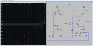
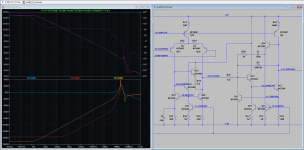
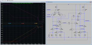
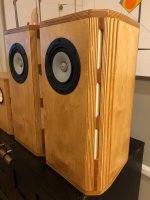
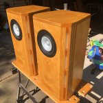
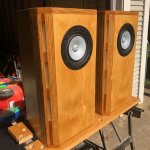
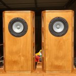
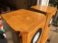
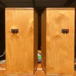
After having settled for the drivers and the basic construction (H-baffle with 2 Peerless SLS-10, naked TB-1320 and Neo3), I am now considering what should into go into the equalization and positioning of my first OB speakers.

Especially two points got my attention:

First, the approach of Dr. Geddes (p. 7 and 9) et al. to broaden the stereo sweet spot by compensating the distance induced SPL loss from the far speaker by an angle induced SPL loss from the near speaker; second, SL´s recent Orion voicing modifications that supposedly improve imaging and perceived tonal balance and that he traces back to our hearing sensibility varying with frequency and listening angle.

As to the first point:

It is usually said that SPL drops with 6dB per double distance. This drop could be accomodated by positioning the speakers so that the distance from the far speaker is twice that from the near speaker, while the listening angle of the near speaker is 60°, which also produces a 6dB drop in SPL due to dipole directivity. This should roughly give equal SPL from both speakers across a wide sweet spot (while, of course, it doesn´t account for timing differences).

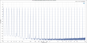
In Floyd Toole´s "Sound reproduction", though, I found a compilation of in-room-measurements of omnidirectional sources as well as of speakers with different directivity characteristics that strongly suggest an SPL drop of 3dB per double distance (fig. 4.13, p. 60). I guess this is due to diffuse or reverberant sound contributing to the measured SPL.

So my questions here are: Do you think my outlined approach is gerenally valid? And if so, which of the numbers for SPL loss should be the starting point?

As to the second point: SL argues that in higher frequency ranges we are more sensitive to sound coming from angles around 30° than to sound coming from the front, making harmonics and overtones sound too bright compared to their fundamentals, which in turn not only leads to a perceivedly unbalanced sound but also to compromised imaging because our brain gets incoherent clues for soundstage reconstruction. (Or at least this is what I understood so far.)

My question here ist this: I found plenty of research on the topic of hearing sensitivity varying with listening angle, still SL seems to be the first to draw these conclusions concerning stereo imaging. So I´m asking myself if his reasoning here ist correct, or if the perceived imbalance of the "old" Orion is really due to dipole blooming in the relevant frequency regions that leads to imbalances in total radiated sound power which in turn could be responsible for the noted effects. What do you think?

Thanks in advance for your feedback & input!

DIY Phase plugs for speaker drivers?

Hi, I'm playing with diy phase plugs for small speakers, I was wondering what will they do on very small speakers like 2 inch .
modifying a pair of 2 inch speakers from dust cap to " phase plug " improve the high end ? for such a small cone removing the dust cap that ( I think acts as a cone as well ) will reduce the size of the cone -> reducing the speaker's sensibility ?.

I did this on 3 inch full range drivers, it improved the mid-highs , highs and made it sound better, significantly. ( bass would be a problem because some air will escape the voice coil gap. Tho there is a spider and no magnet vent.

It can be made out of wood pretty easily, I made them from this hard foam rod,
Ignore the shitty encolsure , I had time to waste with this and a passive radiator , sounds better than it looks 🙂 .
- Bruno.

Attachments

  • 20250202_182011.jpg
    20250202_182011.jpg
    194 KB · Views: 65
  • 20250202_181955.jpg
    20250202_181955.jpg
    208.6 KB · Views: 57
  • 20250202_181921.jpg
    20250202_181921.jpg
    170.7 KB · Views: 56
  • 20250202_181907.jpg
    20250202_181907.jpg
    192.8 KB · Views: 55
  • Screenshot_20250202_182750_Gallery.jpg
    Screenshot_20250202_182750_Gallery.jpg
    140.7 KB · Views: 54
  • Screenshot_20250202_182741_Gallery.jpg
    Screenshot_20250202_182741_Gallery.jpg
    111.2 KB · Views: 52

Audison LRX1.2K Overload protection circuit fault finding

Hi all! Before I strip this down and get too deep into diagnosing, I wanted to check here first for any potential insight or "common issues" on what this amp is doing. It is an LRX 1.2K with no previous repairs, visibly fantastic board condition with no signs of vibration damage, condensation residue, etc.

It powers up, SMPS PWM good, class D switching good, idle current at 12v is 5.8A. Seems high but i'm not sure what is normal for these. Most of that is output section. Nothing getting worryingly hot on the thermal imager.
  • The main relays engage, but there is no audio output, and the Overload orange LED is lit solidly. From the manual I gauge that audio is muted during this protection mode, and the amp should self-reset and unmute, which it does not. The muting appears to happen on the detachable preamp board as I have no sine wave at any of the header pins to the main board. There is no load attached to the amp at all. This fault is the same whether or not any RCAs are connected.
  • With the class D driver card removed (DLD.1) the amp hard-protects with all the LEDs illuminated.
  • With the auxiliary supply board removed the amp stays on, 1.3A draw, but of course no class D switching. The orange Overload led is not lit, so I can almost rule out the CPU.1 board being an issue i think.
  • With the CPU.1 board removed obviously nothing happens other than the main relays engaging. Green light is on, orange OL light is not.

I suspect there is an issue with either the DLD.1 board (as I believe the overcurrent sensing may happen here) or the preamp board. There was a previous thread I saw which mentioned the top-left JFET marked GK on the DLD.1 had something to do with overload muting, I did remove it and powered up but there is no change in behaviour. I also changed the TL072C beside it as a stab in the dark, no change. There are no dead-short semiconductor parts or caps on the board and it all looks visibly good.

Although this is what the amp is currently doing, I want to mention that when i powered it up for the very first time, i DID in fact get audio output, and the overload LED was flashing which the manual suggests is "rare" overcurrent, seems to be more of an indicator as it does not mute output. While powered up initially, regardless of whether I had an RCA in or not, there would be slight "wobbling" voltage on the output terminal, a few mV of DC up and down with no obvious rhythm, and then amp would sporadically disengage the main relays with the orange OL led going solid, and then reset and re-engage the relays. Between this time of initial diagnosis and what the amp is doing now, no changes were made to the circuit and nothing was shorted by a probe, all I did was remove and reseat some of the daughter boards, and the change in behaviour kind of slowly progressed to this current state. In its current behaviour with the audio permanently muted and OL led solid, there is no mV bouncing around at the terminals, which suggests that was coming from the preamp board perhaps.

Any past experience you may have will be appreciated before I spend a lot of time on this! Thanks!

Attachments

  • WhatsApp Image 2025-01-30 at 11.14.24_5b71dee4.jpg
    WhatsApp Image 2025-01-30 at 11.14.24_5b71dee4.jpg
    906.3 KB · Views: 59
  • WhatsApp Image 2025-01-30 at 11.14.24_116bb444.jpg
    WhatsApp Image 2025-01-30 at 11.14.24_116bb444.jpg
    425.3 KB · Views: 54
  • WhatsApp Image 2025-01-30 at 11.14.24_9429c900.jpg
    WhatsApp Image 2025-01-30 at 11.14.24_9429c900.jpg
    471.3 KB · Views: 50

Arcam A22 Preamp Section

Hi all. Have an Arcam A22 with two separate problems, maybe three. First two result in protection fault problems.

When I disconnect the preamp from the main board, as stated, protection fault, unless I warm up Z9. Then the power amp runs fine. Connect the preamp, Either by internal switch or RCA cable, and fault returns. Running pre out to separate amp yields a low signal with no volume control. I can however hear clicking through the speakers when turning the volume control in either direction. Using RCA to connect pre to main gives immediate fault whether connecting right or left channel.

Thinking the most likely cause for preamp failure in both channels is the one ic common to both sides. + and -15v are getting into the board, but I haven't trace any further. Any other ideas?

So, as I said, seems like two different problems. Z9 all on its own, and the preamp board. Feel free to suggest something else.

Z9 seems to be a death sentence based on cost and availability. I'm crazy enough to consider grounding pin 9 to disable the fault circuit. Seems like I have a boat anchor if I don't. Any opinions here?

Oh yeah. That other problem. Left side, main speaker output. 9k resistance across output, any and all conditions. All three other speakers measure open circuit. No obvious audible problem.

Help me please!!!

Any benefits to mounting a tweeter above the cabinet?

Bowers & Wilkins mount their tweeter assembly above the cabinet - supposedly it's more acoustically decoupled and cleaner in its solid enclosure. See pic below.

Are there any benefits to mounting a tweeter above the cabinet in a similar way, like in a heavy aluminium tube? The main cabinet for a 2-way could have the mid-bass mounted right at the top so as to be as close to the tweeter as possible.

One benefit would be that you could easily swap tweeters when experimenting.


705 S2.jpeg

Parasound P3 adjustment trim pots do what ??

Hi Guys n Gals.

Friend has a late model P3 pre.
He's wondering what and how the trimpots TVR1 TVR2 TVR3 TVR4 should be adjusted.
His balance is of to one side.

Thanks.

PS it seems Parasound have been bought out, When did that happen, and who owns them now ??

Attachments

Cardioid and Sealed cabinet ala John Kreskovsky

Cardioid OR Monopole (sub)woofer cabinets à la John Kreskovsky

Has anyone completed a woofer system with multiple woofers in dual opposed sealed configuration, but instead utilizing DSP and selectable settings to transform in between sealed and cardioid-like behavior, when preferred?

Reference:
U-frame DIY
NaO U-frame
Gradient woofeer equalization

Newby question: Hybrid bridge rectifier

I hope I drew these schematics correctly and its not a stupid question. Which configuration makes the "best" hybrid bridge rectifier, A, B or C? I have a "hunch" of which I like best, but no science behind it. I found schematics in my stash to be varying.

A: NEG (diode/diode) - POS (tube/tube)
B: NEG (tube/tube) - POS (diode/diode)
C: NEG(tube/diode) - POS (tube/diode)

HybridBridge.png

Kenwood KR-5340 bias

So the service manual for the quad KR-5340 recommends breaking the B- connection and inserting an ammeter to set the bias by measuring the current. I'm wondering what the value would be per each pair of outputs (two pair per channel because it's a quad) when measuring across one of the emitter resistors. Each emitter resistor is 0.47 ohms. So am I looking for 14.1mV and 18.8mV when adjusting VRe1 and VRe2 respectively? Or half that because I'm only measuring across one resistor, i.e. 9.4mV and 7mV?

SM Bias Instructions.jpgAmp schematic.jpg

Experience with FedEx?

I'm fed up with Fed Ex.

I have a package from Madisound... they shipped it FedEx... it was supposed to be here tomorrow or the day after ( 11/13 or 11/24).

Instead, "Surprise!" FedEx announced it was coming early, on Sunday 11/12. It "will be here from 7:30AM to 10:30AM".

No! no! So, I tried to get them to delay it... but after half an hour trying to get with them I gave.

See... it's my wife's Big Birthday this weekend, We got family here for the whole weekend, events planned. So, I accommodated the pendejos at FedEx. We will go out to dinner on Sunday and do brunch at home. At the last minute my wife told me that we should do dinner at home on Sunday instead ( we were gone all day Saturday ).

At 8 AM, package out for delivery, Delivery scheduled before 1o:30 AM.
Sure enough.. on Sunday at 10:30, no package. Still out for delivery.
At 11:00 AM, delivery changed from 10:30 AM TO 1:30 PM.
At 2 PM no package, delivery changed to End Of Day. Still out for delivery.

Now, this is a Big Birthday and FedEx is a bunch of incompetent nincompoops, do they think they own the market?

Anyhow, we're home, it's now 3PM and still no package.

Tomorrow I'm gonna call Madisound and tell them I will NOT deal with them if they insist on using FedEx.

I get lots of packages... Amazon Logistics is by far the best.... then USPS and UPS. DHL comes through, Costco and Fed Ex are by far the worst.

I am so pissed... being forced to stay home for a lousy $200 package because Madisound shipped it "signature required"... with FedEx.

WTF are they thinking?

Do you have the same issues with FedEx?

Marantz Model 9 - Restoration resistor choice

I am recapping a Marantz Model 9. While I was in there I noticed some of carbon composition resistors have drifted over the years. Are there any resistors that must stay carbon composition for best performance? And any positions that would benefit from a specific type like wire wound? I plan on using thin/thick film resistors as long as they have the correct voltage rating and low ppm.

http://zilla.li/Resources/PDF/Marantz_8B_9/Marantz_9_Service_Manual.pdf


Thanks!

Square wave overshoot

Hi there,

I am playing with the amplifier circuit below in LTspice.

Amp .jpg


It seems quite stable when looking at gain/phase margins. However, when I feed it a square pulse, the result is this:


Square wave.jpg


I don't really know how to interpret this, is it bad? if so, what could be done about it?

Looking forward to your comments, also in general about this circuit.

Attachments

Designing and building external speakers for 8002D Bluetooth speaker unit

My experiments with speakers and amplifiers located in the subterranean layer of the Hi - Fi world continues. Subterranean in terms of cost.

Here is my latest project, which is proceeding nicely: When the TEA 2025 amplifier stopped working properly, I hit upon the idea of connecting an inexpensive speakers to my existing Whafedale Diamond IV speakers. The results were surprising, while bass was totally lacking, it could be boosted using the music player (Musicolet) equalizer for acceptable levels of musical enjoyment.

I am in the process of building a set of speakers specifically for this little Bluetooth amplifier, with some success. I am getting 70 dB at 1 metre with these connected to large vintage floor standers of 89 dB sensitivity.

I had a few questions though.
Projects by fanatics, for fanatics
Get answers and advice for everyone wanting to learn the art of audio.
Join the Community
507,824
Members
7,889,758
Messages

Filter

Forum Statistics

Threads
406,317
Messages
7,889,758
Members
507,824
Latest member
bomberix