IPAD AIR 2 16GB Gold

Selling my IPad Air 2. It's worked perfectly since I bought it. Wi-fi only, no carrier. Really nice condition.
Gorgeous display. iOS14. Tiny little dent in far corner (see pic) that you'll never even notice. Comes with charger and Anker bluetooth keyboard/cover.
Battery power is still strong.

$170 Shipped U.S. Paypal.

Attachments

  • Ipad 3.jpg
    Ipad 3.jpg
    622.5 KB · Views: 132

Eminence Lab15 - Sound Quality

Hi there. I'm curious about the sound quality of Eminence Lab15 and the other Lab subs. Are they good music woofers? I'm not overly experienced with high end drivers in the sub frequency. I would be crossing under 100hz, likely closer to 50hz if possible to a large pro woofer.

It looks good on paper but I have had mixed results with some Eminence drivers. Probably too high of expectations combined with inexperience so looking for opinions from others who have more experience with this driver or anything to offer.

Thanks

Strings in orchestras sound out of tune

This is probably just me, but here goes...
I love some classical music, but as soon as the violins start up it's like fingernails on a blackboard to me. Am I alone in this? What could be causing it?

I have a theory that it is something to do with them being fretless and the players are going for the true note instead of the note that for example a piano would play. On a piano, E =659.26 Hz, but on a violin (or viola or any fretless stringed instrument) a perfect E at 440×1.5=660 Hz can be played. Is this difference big enough to notice?

Brian

Soundstaging and imaging with soffit mounting?

Hi guys

So I am moving into a new place, and in the new place I will have to move my main system into what will be my study. But this room is small (circa 3m x 3.5m). I will be putting (floorstanding) shelves on all the open walls (books and LPs). So either I put the speakers in front of the shelves, which will put me about 1m away from the speakers, or put them against the walls, and build shelves that will fit around them. The listening distance will not be much better, but it will be better. I am just wondering how this will affect the sound.

On the speaker front I currently have two options.
1. I have a pair of AR91 speakers
2. Alternatively, I have a pair of Wharfdale Super12 RS/DD (I have actual measured TSPs for these) that I can mount in Tannoy Berkeley cabinets (I have uncut baffles for these, so I can go vented or sealed). If need be I can also custom build a pair of cabinets for these (the recommended size for these is 5 cu.ft. and the Berkeley cabinets are only 3.5 cu.ft.).

So, what would you guys suggest? I do have a pair of P Audio 15" woofers, with P Audio PH220 alu horns and compression drivers, but I don't think this combo will work for nearfield listening, so the above two are my main options. Any suggestions will be appreciated. Note, I don't have the budget to buy something else, so these are my options.

Thanks,
Deon

NAD 2700 Alignment problem.

Hello,

I replaced the relays in my NAD 2700 THX Power amp so I thought I would do an alignment while I had the box open.

The problem I'm having is with setting the Idling voltage. I did this a few months ago and had no problem getting the 7.5mV. Now the most I was able to get was 3mV maxing out the trim-pot. The amp was making a buzz when I got that high. I'm getting the same on both channels. I went ahead and set both channels to about where the trip-pots were before I started, this gives me about 1mV. I played some music through it, it sounds pretty normal.

Any idea's where to start?

I'll probably take it to a shop (any recommendations in San Jose California?)

Thank you for reading. 🙂

Attachments

  • Screen Shot 2021-03-21 at 5.37.06 PM.png
    Screen Shot 2021-03-21 at 5.37.06 PM.png
    95.7 KB · Views: 116

D.a.s cx-12 data needed

Hello I have purchased a pair of d.a.s cx12 fullrange speakers, they were a very good offer, but I have been unable to find any specs on them, they are mounted in a stage monitor cabinet, I would like to build a new enclosure, I attach pics, the pics are not of mine, but pulled from internet, seller guarantees they are in mint condition.
So if you have specs it would be most welcome

Attachments

  • Screenshot_20210320-095920_eBay.jpg
    Screenshot_20210320-095920_eBay.jpg
    729.4 KB · Views: 131
  • images (1).jpeg
    images (1).jpeg
    6.9 KB · Views: 128
  • Screenshot_20210320-100855_eBay.jpg
    Screenshot_20210320-100855_eBay.jpg
    848.4 KB · Views: 131

Goldmund modification

Hi, i was just playing with the bias circut when the cordell output correction idea cae to mind.
In this case i was looking for a "simple modification" that makes sense.

At first comparing to resistor bias or fixed bias...

Could it bee that this current driver drive 😉 ?

This simple bias with error correction ? Any comment ?

Bias current abt 7mA.

Attachments

Bryston power supply mods (MPS1 to MPS2 or PS3)

Unlike the schematics you can find on the internet for many Bryston products over here I can't find it for their power supplies.

I was wandering if there are people who have made modifications to a MPS1 so it could meet the level of a MPS2 or PS3 power supply?

Or did some modifications like Alfetta87 describes at internal mods for the BP25

I've changed some parts inside, like the voltage regulator (standard are cheap fixed regulators), bypassed the output caps, and varniched all with C37 lacqueer.

Altec VOTT A7 using CAD and CNC

Whilst I'm developing a smaller Altec bass horn for my own system, I'm using part of that experience to do a CAD/CNC Altec VOTT A7 cabinet.

Attached are the initial drawing from my engineer CAD mate.

This will be built in Euro Birch Ply, 19mm.

A significant change over the original is the central baffle which is rebated into the sides, top and bottom of the cabinet.

The horn sections will be bent by CNC'ing the multiple grooves into the back of the ply. This creates an easy bend. CNC'd brace supports are used as the template for the 31 inch radius curve.

The back 2/3 of the cabinet will be fixed, while the top 1/3 will be removable.

As a decorative feature, we'll create an oval shape port at the front, which will sit in a removable panel, per the original design. This way we can add different size ports to suit the tuning of the cabinet. The initial sizing is smaller than the original A7…and the current pic shows the oval cut out too large. We’ll target a size of approx 30cm x 7cm (12 inches x 2.75 inches).

Altec 515's will be used in this version.

I suspect the cabinet will be heavy, with as little cabinet resonance as possible.

Andrew

Attachments

Inverted triode vs. regular follower

Hi everyone.

I've come across the inverted triode configuration a couple of times, also on diyaudio, and most times the benefit that the designers claim is the low output impedance, which basically is close to 1/gm. The price to pay is a voltage gain which is a fraction of one.

But 1/g happends to be the output impedance of a cathode follower too, which delivers a higher gain, with great input impedance figure and much higher anode dissipation (versus grid dissipation on the inverted configuration).

This leads me to think that I'm missing something here...
What is the benefit of an inverted configuration compared to a follower topology?

Thanks!

Hafler P505

Hi,

Has anyone come across Hafler P505? I looked at the Hafler's webpage but didn't find any manual. Not much talk on the internet about it as well. I am wondering if anyone here knows about this amplifier. Claims to have same power specs as DH-500. It has quarter inch inputs on the back and level controls. I think they are balanced inputs. Any help would be greatly appreciated.

This is my first post at DIY Audio, so if I have posted this at a wrong place please let me know.

Thanks,

wharfedale glendale 3xp fault, Help!

i have a lovely pair of wharfedale glendale 3xp's which i got dirt cheap but have discovered one of the mids is faulty. no noise atall comes out of it even when connected to seperate amplifier. so i dont think is the crossover. i have no idea whats wrong with it and i cant find any information about these drivers or replacements so i cant even buy originals. would love to fix if possible or if need replacement need to know technical info to find something suitable.

anyone know anything about these lovely speakers?

thanks H

Driving 2x TDA749x boards from a single CSR8635

Hi Everyone, first time poster here.
I've been digging around these forums in preparation to build some active speakers.
Clearly there are lots of cheap Chinese boards available and the TDA7492/8 and TPA3116 seem very popular.
I noticed when looking at the popular mods that it's quite common to convert these from single ended to differential to stop a lot of the unwanted noise (a big thanks to @doctormord for the guides, they're very helpful)

This got me wondering whether anyone has driven two completely isolated boards (including separate power supplies) from a single CSR8635 bluetooth module on the first board.

Is something like the attached possible?
I recognise that the first board has other benefits given the CSR8635 is local, such as mute/standby.
I guess these could be added to the second board by introducing something like an opto-isolator to drive the functions.
The key thing would be the two amplifier boards are powered by separate PSUs.
Thanks.

Attachments

  • CSR8635 TDA749x.jpg
    CSR8635 TDA749x.jpg
    109.4 KB · Views: 311

IceEdge

Hi

I presently own a IcePower 300AS1/300A1 stereo amp. I really enjoy it but can’t stop wondering if the sound of the IceEdge is better than the IcePower 300 series.

Are these IceEdge available yet and to who ?

100W @ 4 ohm is more than enough for my needs, I believe I read they have a 1200 W available (way too pricey to simply satisfy my curiosity)

Thanks
Eric

Lanzar Optidrive 2500

Here I have this Lanzar Optidrive 2500, which blew its PS. Was using IRFZ44 with 100ohm gates. A bunch of PS drivers items fried. Board is using 4401/4403 for drivers.

Reference thread: https://www.diyaudio.com/forums/car-audio/281020-lanzar-optidrive-2500-a.html

All pre-drivers Q60-Q64 need to be replaced. The board also burned as well. Will be using the link as reference for re-conditioning.


I am unable to get a solid 'lock' on the SG3525 pins 11/14 with my scope. Usually this is never an issue but for this amp its just creating solid 'bars' on the scope at 0vDC and ~7vDC with information between which I cannot lock onto. Usually I can see outputs of this and similar PWM ICs no problem.

I suspect the SG may be hurt on account of all the pre-drivers shorted/blown/etc.

Does this SG3525 look OK?

SG3525
1: 0.995
2: 1.089
3: 0.024
4: 0.197
5: 2.054
6: 3.839
7: 2.054
8: 4.93
9: 5.32
10: 0.025
11: 3.676
12: 0.004
13: 8.42
14: 3.663
15: 14.14
16: 5.19

LTP transistor Matching

Hi guys ,
I have been working on blameless design for quite some time , the problem I am facing is increased DC offset of around 70 to 140mV. With a tail current of approx 2mA I am getting a offset of around 140mV and if I drop the tail current to 1.2mA per device I get a offset of 70mV. I understand this is happening due mismatch of the LTP transistors Vbe and Hfe . Would it be advisable to use something like a MMDT5401 i.e dual matched PNP transistors in small SOT 363 package ?

Regards

Speaker Design Checklist. What should I watch out for?

I've been reading up on different things to consider when designing a set of large towers from scratch. I've read all the stickies, I've used the search, I've googled terms I haven't seen before, and now I just want to make sure I know of all the variables/concerns/etc before I start down a design path that has flaws.
Here is a list of things I'm taking into consideration before buying anything/finalizing any plans. Please comment with your additions so that I and others can know what to look into:

  • Baffle step
  • Edge diffraction
  • Phase alignment/Time alignment
  • Comb filtering
  • Driver sensitivity matching/padding
  • Polar response/Lobbing/Lobing/directivity
  • Beaming
  • Cone breakup
  • Cabinet construction/bracing & resonance problems
  • Impedance/ohms (total and per driver)
  • Crossover types (orders, L-R, etc)
  • Box type (sealed, ported, open baffle etc)
  • Port tuning & air speed if using ported box
  • Power handling (of drivers and crossover) & desired SPL
  • Driver distortion of selected drivers (linear and non-linear)
  • Cone excursion of selected drivers
  • Form vs Function (Looks vs sound quality)
  • Cost and build time concerns
  • Consider listening room size/acoustics/listening position
  • Consider desired music type
  • What do the guru/expert's think of my design?
What else?

LED PCB click here

PCBONLINE manufacture FR4, Aluminum PCB for many customers,
LED customers normally come from Turkey, we always have advantage in this field, high quality and reasonable price, accept price discuss and provide discount for customers.
led-pcb-2.jpg

LED PCB: PCBONLINE - LED PCB Manufacturing & Assembly, EMS Service Provider

Aluminum PCB:Aluminum PCB Manufacturer - PCBONLINE

Coupon: PCBONLINE

Hi all from Australia

Hi all

I am a Civil Engineer just starting out in audio electronics. I am never going to have the level of knowledge I see in many members here but have been learning electronics by experiment and simulation for the last year. I have many of the tools needed to undertake diy projects and have even made my own pcbs recently for micro projects.

I am really keen to start building some audio projects. I appreciate good audio, my setup consists of a NAD 7225pe with a set of Whafedale Diamond 10.1, but I am no audiophile. I thought I would start with the ACA and ACP+ before realising some parts are very hard to get. Anyway, the pcbs and fets are in transit from the store and eBay.

I am quite keen on testing my skills with either a chip amp or old retro amp on a single sided board. The info in the forums is a little overwhelming, is there anything recommended to build for a beginner knowing my basic speakers and setup ?

Cheers

Richard

Calibrating DIY Frequency Response Measurements

How would one go about calibrating a frequency response measuring setup (I’m using UMIK-1 and REW) to measure drivers so as to generate SPL vs frequency curves like on driver datasheets? What I would like to do is measure drivers I have to compare with the factory curves. I have a pretty good setup and have gotten excellent correlation in terms of the shape of the curve (specific peaks and valleys in the response), but my SPL level is off.

I have some new RS150P mids on hand and at 500Hz, the SPL is stated as 90dBSPL on the factory curve. I’m considering just adjusting the output of the amp so that my readings end up with that value and keeping that amp as a dedicated amp for driver measurements. Not “precise,” but good enough for hobby work?

Hell's Belles (Two) Ground Loop Hum

Hi Folks;
I came across a Belles Two Stereo Power Amplifier with a blown line fuse. I can't find a schematic but my guess is the four T03 devices on each heat sink appear to be a (cascode) arrangement rather than paralled. One of the final outputs was shorted. After replacing that T03, all was good.....I thought.
As with the Amber 70 amp I have been struggling with, there is a low level hum when both channels are connected. The Belles amp is quiet if nothing is connected to the RCA inputs and quiet if only one channel at a time is connected. This is the case even when a battery powered mp3 player is the source. (no possible ground loop other than between the inputs themselves) The two channels just don't get along with each other!
The RCA input jacks are isolated from the chassis. I have inserted a 10 ohm resistor between the RCA shells and the connection inside the amp. No effect.
Thanks again for everyone's help, Peter in Canada

Attachments

  • DSCN2057.jpg
    DSCN2057.jpg
    932.3 KB · Views: 184
  • DSCN2058.jpg
    DSCN2058.jpg
    895 KB · Views: 191

Pioneer SA-506 (NEC B616A/D586A pair)

Hi,


I found at the local waste center a Pioneer SA-506, 40 yo and perfectly working but the lights of the VU meters. With original Nichicon caps (no bumped top on any) Pioneer SA-506 | Pioneer SA-506 vintage amplifier on vintageshifi.com.


power transistors are NEC B616A/D586A , How are they according your experience/knowledge please ?


I know it's mass market, with a 100 VA trafo and pots from prehistoric ages but it looks cool to the eyes ! I have already 4 complete hi-fi system, so no really room for more but maybe the kitchen !


Worth the recaping or better to leave it original for the vintage enthusiasts ?

DSP (or similar) powered by LiPO cells?

I was thinking about all of the interference from SMPS and had an interesting idea. I know alot of people run their systems from batteries to get rid of mains issues.

If we assume that a critical low voltage component (DSP, codec chip, etc...) is consuming low power, would it be an idea to run it from a small bank of LiPO batteries? And have them automatically charge when it isn’t being used?

Many of the small atmel micro boards (feather, arduino mkr, etc) have this functionality built in. There are a number of low-noise linear supplies that can handle the small drop in voltage as the battery is drained.

I can’t think of a downside. (Assuming, of course that it is not being used 12h/day daily to kill the batteries from charge/discharge cycles)

My thoughts on the Burson Audio V6 Vivid

First off, I would like to thank Carlos for the opportunity to try out a pair of the Burson Audio V6 Vivid op-amps. Also, my apologies for taking so long to write this. Nothing in 2020 seems to be going as planned.

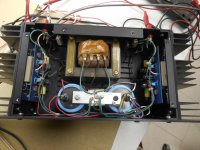
I’m using these in a AK4497 based DAC. The board has sockets installed so swapping the op-amps is easy. After nearly 40 years in electronics, I have lots of parts sitting around to play with. Some of the op-amps that I have tried with this DAC have been the 5532, OPA2604, LM4562, OPA1612, MUSES8820 and the MUSES02. They all work fine in this DAC and I could live with any of them. However, of all of them my favorite is the MUSES02 for this application. So, I only compared the V6 to the 02.

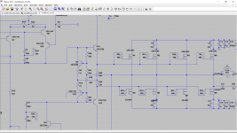
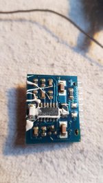
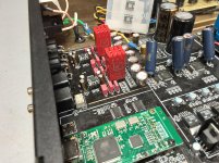
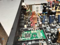
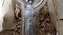
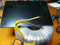
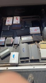
When I first heard the V6, I was reminded of the smiley face EQ. Back when graphic EQ’s were popular you would see EQ’s with the bass and treble faders boosted and the mids flat or cut. The V6 seemed to have a U or V shaped EQ to it. The first things to stand out was a strong well defined bass, an extended and detailed upper end with a wide deep and layered sound stage. The mid’s however were missing or covered over by the high end. The extended upper range made things like horns, strings and cymbals a little grating and fatiguing over time. This was not an issue with any of the other op-amps I tried. Around the 80 hour mark, I thought I would try shielding the V6’s just to see if that would help the upper range. That is the second picture with them in a grounded copper foil. I checked the PS and outputs again with the scope. Shielding did not seem to improve anything.

Over the next one hundred hours or so, I switched back to the 02 a few times. Each time listening to the V6 was like being at a clear bright sunny beach. Switching to the 02 was like being at that same beach but with a good pair of sun glasses. With the glare and brightness gone, all the subtle details reappeared. The little breaths of a horn player or fingers moving on strings were back. Listening with the 02 was more relaxed and musical. The V6 was more on the analytical and cool side. Also, while the V6 has a large deep sound stage with a musicians in the room sound. The 02 has a huge 3D holographic sound stage that puts the listener in the room with the musicians. The V6 and 02 seem to be complete opposites in their sound. Kind of Yin and Yang.

I normally do not expect a change in op-amp sound after a few hours of warm up. However, around the 140 hour mark, something changed with the V6’s. The upper range mellowed considerably and the mid-range showed up. The FR seemed a lot flatter. With about 250 hours on them now, they are easier on the ears. The up right bass sounds fantastic, the mid’s are present with a slight warmth and horns, etc. on the upper end don’t have me reaching for the skip button. Also, the subtle details in the mid’s are there now. There is still a bit of glare and edge to the upper range. This can be an issue with some recordings or long listening sessions.

In the end I would say the V6 Vivid is a great op-amp in the right system. I have an older headphone amp that leans a little too dark. I plan on trying the V6 Vivid in that unit when time permits. I have a feeling that the V6 Vivid’s detailed and analytical nature will work well in the studio for checking final mixes, etc.

Thanks again Carlos.

Attachments

  • 20201007_113036.jpg
    20201007_113036.jpg
    836.3 KB · Views: 345
  • 20201007_115901.jpg
    20201007_115901.jpg
    569.3 KB · Views: 272

Volume size box help.

I have a project in fact this is exact replica of the cynosure part express speaker, a center line array.

My real question is the original box has a size of 24x4x14 that give .519 ft volulme,

In the project they say the best would be to put the port up front, instead on the side on the original plan, So I calculate if i put the port on the front that would give me a 34x4x10 and a .516 ft volume. compare to .519 ft volume

Is their any problem with my new size box ? Or it's only the amout of volume that is important, in this ? Sorry If it's sound has maybe a newbie question.

Thank you for your help.

Transformer secondary current determination for wires

Hi,


I'm looking to buy some wires and THT connectors for my power supply PCB, so looking at the kinds of current the wires and connectors will need to take.


I've already got some JST-XH connectors which can take 3A, and I've got some 24 AWG 40/0.08 spec wire that the sheet says can take 2A carrying current and 7A instantaneous current.


I'm looking to swap out my toroid for this 18V dual secondaries (RS PRO 230V ac, 2 x 18V ac Toroidal Transformer, 160VA 2 Output | RS Components) which says 4.44 A on the secondaries.


Does this mean I have to make sure my board connectors and hookup wire will need to be able to carry > 4.44 A or is the toroid specs based on usage from how much the amp will pull and effectively the maximum current it can supply, and thus the 2A connectors and wire I have will be fine?


What determines the maximum current the amp will pull?


Thanks

another Blameless Design

Hi Guys ,
I found this schematic , and have built this. from what i understand this is a blameless topology . it sounds good and transparent , but when i tested this on the scope the sine wave output is perfect from 5hz to 25khz , but square wave gets slightly distorted above 5khz , does that effect the sonic performance of the amp ?

Attachments

  • xyz.jpg
    xyz.jpg
    161.8 KB · Views: 510

XS3868 ver 3.0 Bluetooth Stereo Audio Noise After 5 seconds idle

Hi,

I have recently modified car radio case and added a a2dp module from eBay to it. It is the XS3868 ver 3.0.

But I have one problem. The sound works, the buttons too. But when I play sound using the a2dp profile (audio sink) and pause a audio track or don't play audio at all after 5 seconds a hum/buzzing sound starts (around 50hrz).

It is the same problem as another person had on eevblog.
Post #15 about the noise introduced after 5 seconds idle using Android a2dp profile, is the same as what I have.

Topic:
https://www.eevblog.com/forum/beginners/bluetooth-audio-someone/

Here is the diagram (shown in the video on the prototype board)
http://i.imgur.com/R752N7X.png

I have tried to hook it up to another amp, same problem. I tried headphones and those work without the buzzing sound after 5 seconds! I don't understand why..

Video of the buzzing sound:
https://youtu.be/9YBVj6Cl-cE

What am I doing wrong here, or what do I miss?
Maybe adding two 220n ceramic caps to audio out, will this really improve it?

Best regards,
ESXi

Need Help Choosing a DIY Design

I am looking to build a new 5.1 system that will be primarily used for movies.

My current setup was built using Blues MTM for towers/center, and Blues TM for surrounds. I have enjoyed them, but I am ready to move on to something else. My budget is around $1000 a pair, preferably less. They will be powered by a Denon AVR X3500 and will need to be 6-8 ohm. Tower placement will be an issue as they will need to be fairly close to the wall and have furniture next to them. I was considering finalists or Statements, but ruled them out due to these issues. I was also looking at ER18MTM with ER15 center, but I don't know what I would use for surrounds. The surrounds will be wall mounted and the center will be on a media cabinet below the tv.

Any design I choose must have a matching center and surrounds if possible. I am not as concerned about bass, as I have a PSA S3601 sub. Whatever I go with should out perform the Blues speakers I have now.

It seems every time I find a design I like it either doesn't have a matching center, uses discontinued parts, or cant be driven with my receiver.

Any suggestions would be greatly appreciated.


Thanks!

Source/load Z relationship?

Single 5842 RF tube line preamp w/Magnequest output transformer model "DS 050/600," 3 output taps = 3 gain choices from 8 to 21.3 dB. My best understanding is 600 ohm output w/maximum gain of 21.3 dB. Currently wired for 18 dB gain with lower output impedance, estimate 500 ohm.

The total load is 3 different parallel amplifiers, 8.7k ohm total, as follows:
  1. Main amp: 100k ohm input Z, gain 27 dB, .97Vrms = full power @ 8 ohm > 90.5 dB satellite speaker, 9 ohm
  2. 2nd amp: 335 mV, 47k Ω > reverberant field speaker system
  3. Dayton SA1000 subwoofer amp: 12k ohm, gain/sensitivity not specified but rep said likely .775mV (industry standard for domestic audio) for full output @ 4 ohm > dual 4 ohm subs in series, 8 ohm, 89 dB per pair (one SA1000 > 2 subs p/c)

Above source to load ratio appears to be a very reasonable 1:16. Pros recommend 1:10 minimum.

A professional with a lot of SA1000 history said SA1000 had enough gain > same 8 ohm sub load, even with Edgarhorns specified over 100 dB, at least 10 dB higher than my application.

Why might my SA1000 gain seem to be lacking? Both SA1000 indicate similar gain, so the gain is correct and typical.

Thanks!

Basic Crossover Calculator Question

I have some very basic questions for input into a 2nd order calculator (this one is on V Caps site Speaker Crossover Calculators by V-Cap )

Say my tweeter Re=3.18, would I put that into the high pass impedance (with no adjustment for the inductor?

Say my woofer Re=3.7, would I add the inductor's dc resistance of 0.41 and input 4.11 for the low pass impedance?

With the phase shift,
For the tweeter, I would wire the amp's + through the cap to the tweeter's -?
And the amp's - to the tweeter's +?

For the woofer, I would wire the amp's + through the choke to the woofer's -?
And the amp's - to the tweeter's +?

image of calculator with values and schematic attached.

Attachments

  • CrossoverExample.png
    CrossoverExample.png
    49.7 KB · Views: 265

CARVER's PM - silent and safe ...

Another thread about PM's ...

So many tweaks I've seen on the net, surprisingly I did not found the one I use to do on most of the PM's I own or re-sale with Electrostats systems :

I would not recommend these mod's for PA use, but I'm using PM's (1,5 - 1,5a - 1200's) since years without any issue :

1. Remove the Fans, replace with last generation 80mm PC Fans (I'm using the Arctic brand) with high flow and low noise. There are plenty of DC supplies (3 - 12v) which enter easily the original rack of the PM1.5a, a little bit trickier in the PM1.5

2. After removal of the Fan PCB, there is plenty of room for an additional 2x 30amp temporized relay. There is a 80V supply that you can find easily at the caps end in the Power supply board ...
I see the Audiophiles grinn ... But I sleep better when I let my friends with these 1000w beasts under protection !

Attachments

  • Carver.JPG
    Carver.JPG
    174.9 KB · Views: 88

What is better? HDMI audio extraction -> i2S or extra D->A->D step?

Hi everyone, I'm trying to determine the lesser of 2 evils.

I have an Onkyo AVR (RZ-820) that does a great job with connectivity, movies, network streaming, Tidal, etc but leaves a bit to be desired on the room correction/dsp front.

I’d like to add an external DIY box with a DSP (ADA1452/62 or similar), dac and a number of monoblock amps to drive my main speakers for music listening, while keeping the receiver setup for tv and movies.

I want to try my hand at building an amp based on the some of the boards that others have so carefully designed on here while using my existing hardware as a digital source. Essentially just use the onkyo as an overblown network streamer box (because i have it and already like the workflow using it)

However this receiver doesn’t have any traditional digital outputs, but it does have an HDMI to Zone 2 that can be used to output the digital audio/video.

Which do you think is the lesser evil:
1) use one of the myriad of HDMI audio extractors to get I2S from and pass that to the DSP and down the signal path... (with whatever jitter or other artifacts being introduced as the downside)

2) Use 2 channels of the analog preamp output (single ended, 1V) from the Onkyo and then use the A/D function of the DSP to redigitize.... the Onkyo has a nice DAC (AK4458) at least...

3) ????

I’m thinking that the combination of the 1V preout with redigitization is worse (it just FEELS wrong to have an extra D/A A/D in there. I know enough, however that sometimes the real-world benefit of one would surprise you.

What do you think?

Kef B110 upgrade for Concertos... Monacor SPH-135AD?

Hello,
any experiences with swapping Kef B110 drivers for Monacor SPH-135AD? I was wondering if they are actually an upgrade and if they would improve the sound of Concertos. I compared Concertos to SBAcoustics Troels 3-way classics and Troels speakers were better, more natural sounding, specially in midrange frecuencies giving a clearer, fuller, more pleasant sound

Thanks

New B&C Speakers driver 18SWX100

Colleague of mime sent me a link for new model of B&C 18" subwoofer driver:
18SWX100 LF Drivers - B&C Speakers

Interesting animal with longer copper voice coil, more cone excursion capabilities and more power input.
The motor is not that efficient though. Dangit! Another miss after my prayers for 18DS152 or 21DS152 with longer coil.

The speaker likes larger box volumes.

Any thoughts on this one?

BIG PSU capacitors but small size

Has anyone looked at the Taiyo Yuden range of PAS super capacitors in relation to making a rather large Class A power amp capacitor block. They are available in 2.7 and 3.0 VDC ratings - but instead of paralleling them as you would normally do with other snap in types or lugged chassis mount caps that have the appropriate DC voltage rating, you wire them up in series to get the overall required DC voltage rating. You then must use balancing resistors across each cap to make sure they share the current evenly. There are tutorials on line to tell you how to work out the appropriate balancing resistor values for a given supply voltage. Nothing special in that at all.

I have made up a +/- dual rail PSU cap supply on matrix board using their 9 Farad / 2.7VDC rated super caps with a total of 12 caps in series per rail to give me 750,000uF (9 Farad divided by 12) at 32.4VDC rating for a "standard" +/- 25VDC PSU capacitor bank.

For those interested, these are only 12mm diameter and 20mm in height with a 5mm lead spacing, so you can end up with a very big supply in not a lot of space. Also good news is that these caps in more than 10 off quantity are only $2.91 USD each at Mouser and just slightly more at Digikey.

I will also use a soft start / mains DC blocker PCB to help with inrush current at switch on, in my next build which will be the MX2 using this cap bank.

For the technically minded, the standard Nelson Pass PSU design that has been posted in this forum on many occasions using 15,000uF caps with 4 in each +/- rail (60,000uF per rail) has an energy storage rating of 37.5 Joules at 25VDC nominal supply, whereas the above supply I am talking about has an energy rating of 468 Joules with an equivalent 750,000uF per rail at 25VDC rating, giving an energy rating of more than 12 times larger.

Also on the plus side, the cost differences between the 2 are quite large with a big saving using the super caps over conventional caps and also chassis space especially if someone did a properly laid out PCB for these caps. You could also then incorporate as many CRCRC or CLCLC type filtering options into the design that you may desire as you have a string of 12 caps in each rail to play with.

I would be very interested to hear other members thoughts on this proposal and even look forward to input from the master Nelson Pass himself as it might be an option for him to use in his First Watt commercial offerings into the future.

More info on these caps are available on the Taiyo Yuden website or via links to data sheets from the Mouser or Digikey product pages.

Gary..

How to remove the brown corrosive glue from Kicker amps

Hi all,

I have a KX800.4 that I used to use around 2005 or so, however I just pulled it out of storage and it goes straight into protection mode

I read a few threads around here and noticed everyone talking about the brown glue, and sure enough it's covering/shorting multiple components together

What's the easiest way to get rid of it? do I really have to scrape it or can I dissolve it with something?

I also have a Kicker ZR360 that went bad back around 2004 or so when I was using it one day, I distinctly remember it suddenly started pumping out about 60hz into the subwoofers one rainy day... wonder if that was the same issue? I actually still have that amp in a box somewhere, might open it up and take a peek

uv8hzLP.jpg

2NaeLsj.jpg

mBpZsSq.jpg

80's PPI-2125 amp

This is an old version black amp from the 80s.

I found this thread: PPI 2125 missing parts with related amplifier.

This amp I'm looking at is using S2N6487s in the PS, but I believe it should have been S2N6488s as they were previously replaced. Either way theres one BJT missing, and a few other parts as well look a bit different and wore out compared to the above thread.

Anyone have a schematic by chance?


Another question. As I comb through my PPI amps, I find that some are using 2n6487/2n6490, and others are using 2n6488/2n6491. I already ordered 100+ of the 88/91s from Avnet.

Can I use the 88 in place of the 87s, and the 91s in place of the 90s? To me the voltage ratings are just higher on the 88/91s.

Easy data sheet showing them all: https://www.alliedelec.com/m/d/34bc368bea952b9eaf1799a01f3d3329.pdf

Toroidal power transformer wiring

Today I started soldering, first the power supply. I was caught by surprise by an enamel coating on the wiring, but managed to remove it. Everything is in a very tight space, but I managed to solder everything; it was a real hassle. I measured continuity on several places and discovered I had no connection between 0V and 275V. I had cut and shrinkwrapped the 250V tap.
After disassembly, removal of the shrink wrap and probing some more resulting in getting weird readings, I noticed the 250V tap consisted of 2 wires. One is connected to the 0V tap, the other to the 275V tap.

I found the enamel coating a bit weird; that wasn't the case with my hammond transformers. And what about the 2-wire 250V tap. Is it normal that the user has to make this connection?

Attachments

  • IMG_20210322_001913547.jpg
    IMG_20210322_001913547.jpg
    901 KB · Views: 663
  • IMG_20210322_001849537.jpg
    IMG_20210322_001849537.jpg
    609.5 KB · Views: 401

Mosfet Gyrator using the IRF840

Could I use the IRF820 instead? With the same values?

I'm thinking of building a Gyrator for my Baby Huey EL84. Maybe even two. And I have IRF820's in my parts bin.

I know very little about solid state things like mosfets, hence my question.

R1, R2 330k Ohm
C1 4.7uF
D1 ZD15
R3 33 Ohm
Q1 IRF840

Also any tips for improving this gyrator?

148189d1259188296-mosfet-gyrator-using-irf840-sch.gif

Attachments

  • sch.gif
    sch.gif
    2.8 KB · Views: 4,768

Magnavox FD3030 / Philips 60hz hum

So I picked up this Magnavox FD3030 but it has this terrible 60hz hum.

I've gone through and replaced all the caps on the main PSU board but the issue persists.

I found this thread from 2012 with someone having the same challenge but it went dead.

https://www.diyaudio.com/forums/digital-source/220729-magnavox-fd3030-philips-cd303-static.html

Any help would be appreciated, I just need to be pointed in the right direction I think.

Indication and control module for tube amplifier

Selling a control and indication module with a tube amplifier.

Functional:
- working measurement of lamp current (1/2/4 channel)
- Control of external relays (3 pcs)
- Emergency shutdown of the amplifier by current deviation ...
All settings are variable and configured through the menu.
AC power supply = 6.3v (lamp filament voltage)

Price 100 USD

Sending anywhere, by mail, CDEK, Boxberyy, Energy, etc.

1610812642542.jpg

1610812642544.jpg

1610812642524.jpg

1610812642519.jpg

1610812642538.jpg

1610812642533.jpg

Demonstration video of the device ????????? ???? ????????? ????????? - YouTube

Phone for WhatsApp communication +7(917)78-10-451
or
E-mail: Klimentiktn@gmail.com

https://vk.com/id533610235

CROWN DC300A repair

Hi all,

I'm refurbishing my CROWN DC300A and I need to replace some of the output and drive transistors.

In my crown I have the following (as in the picture (Crown_transistors.jpg):

- Outputs : RCA 62085
- Drivers : RCA 3626

I've been searching around the forum and I've seen people using MJ21194 for the outputs.

However for the drivers, I did not come to a conclusion which ones would be the best.
I know some people used MJ15024 for the drivers, but while the amp work, distortion and oscillation will be the end result.

Can someone help me?

And since I'm doing this overhaul what other critical components would you recommend to replace?

Thanks in advance

Attachments

  • Crown_transistors.jpg
    Crown_transistors.jpg
    150.1 KB · Views: 101

Another silly mistake.

Built up a Maplin copy lateral mosfet amp.
Powered it up monitoring output for DC with no speaker connected.
Looked at scope -10 volts DC on output so turned off quickly.
A careful visual inspection came up with nothing.
So checked all transistors were the right numbers and they were ok.
So checked every resistor and they were fine.

Looked up at scope and it was still at -10 volts dc.
Silly me hadn't zeroed it !

Amp Noise

Hi,

Just a question. I have two amps wired to the same ground and it seems that moving the gain on the subwoofer amp seems to bring some noise to the front tweeters ( there briged on there own seperate amp). Is this something that can happen and will re grounding the Subwoofer amp to its own location help? I know I can lower the gain on the sub amp to remove it, but then the bass is less performing. I did try an isolator, but it didnt do anything, unless its not suitable one I used. Possibly not connected, but can rewiring the ground from the HU to the amps ground location help?

I havent tried giving it its own ground yet as its a bit of a job to relocate it.

Sub amp Jl1000/1
Comp amp Hertz HCP4

Need some load line help

Will someone take the attached schematic and work up a load line for me so I have something to check against when I am working thru it? The amps designer no longer has his notes and the numbers I get are not making sense to me.
Also any good articles on working up load lines for single ended cathode biased amps would be most helpful. Everything I have found so far has just confused me further.

Thanks in advance to whomever takes some time out their day to help me. I realize it is no quick and simple thing and that I am asking for a lot. Maybe I can help you out with something in trade. I have over 400 tubes. I may have something you need.

Jeff

Attachments

Low Volume

I have a volume problem with going from a Peavey M-2600 into Seismic Audio FL-15P cabs.

The power amp is says 4 ohm minimum 130w rms 4 ohms and the speakers are 8ohm power rating 400 watts.

Years ago I used the M-2600 to power my guitar rack system to two 4*10 cabs stereo...

EXTREME VOLUME!

Now if I go from a Roland FA-06 into a board that uses the M-2600 as the power source I have very little volume...I mean you hear it but no where near the Guitar rig volume.

Even if I go from the stereo outs on the FA-06 directly into the Stereo inputs on the M-2600 I get low volume.

Is the power amp not able to power the Seismic Audio Monitors?....The FA-15P's?

Am I doing something wrong?

Can I do something to fix this?

I'm lost....

I also tried going from the FA-06 into a Korg D-3200 Standalone Deck two channels for Stereo and put the Monitor outs into the ins of the M-2600 and went to the cabs....Sickly low volume...

I'm only a hobbyist and far from a pro...

I'm 61 and I do this for the fun....No Genius here...But I love music and wish to resolve my problem somehow....

Do any of you Guys have an IDEA?

Please help me out.......

Frank

Soundstream reference AirBass remote (wanted)

Soundstream reference AirBass remote (wanted) and literature

Looking at repairing a reference 700sx that has the module inside, but I’m missing the handheld wireless remote.

If anyone has just a spare remote I’d gladly pay for it. Working is a plus. Hoping it’ll be the right frequency? (Not sure how it’s tied to the module)

Please respond or send me a message. Thank you

2 Smart power bars (master/slave how to)

Hi all,
I am in the process building HT with IB (infinite baffle) sub. The sub amp will be in the adjoining room with the sub manifold.

Sub amp will run on dedicated 20A circuit.
Pre-amp, LR power amp etc. runs on another 15A circuit.
Pre-amp is remote controlled and plugged into master plug of "smart" power bar. Turning on the preamp with remote, current flows through the Master plug and triggers slave plugs, which activates power for LR power amp, BD etc.

Now, I'd like to have the sub amp (on second smart power bar, separate 20A circuit) to power on when the pre-amp powers on.

Would anyone know of a simple way how to use 2 smart power bars (on 2 separate circuits), the 1st triggering the 2nd?

Many thanks!

Problems with my... AMP?

Hello and I have a problem.

Are there any Amplifier Anonymous classes for this behavior?

If not let’s start here. I only just restarted this hobby just a couple weeks ago. Wth is wrong with me?

😢

Attachments

  • 07452E9B-0A6B-4F7E-B551-38518D1A6B9E.jpeg
    07452E9B-0A6B-4F7E-B551-38518D1A6B9E.jpeg
    497.6 KB · Views: 98
  • 4FD4D0B4-B01C-4B15-83EC-BD69B59BB921.jpeg
    4FD4D0B4-B01C-4B15-83EC-BD69B59BB921.jpeg
    637.5 KB · Views: 102
  • 35A09A53-A659-48BA-809B-36E0C21207E6.jpeg
    35A09A53-A659-48BA-809B-36E0C21207E6.jpeg
    624.3 KB · Views: 103
  • D9BDA7CB-B83E-4A91-815E-3F750CDCE5A6.jpeg
    D9BDA7CB-B83E-4A91-815E-3F750CDCE5A6.jpeg
    445.6 KB · Views: 96
Projects by fanatics, for fanatics
Get answers and advice for everyone wanting to learn the art of audio.
Join the Community
507,903
Members
7,893,141
Messages

Filter

Forum Statistics

Threads
406,469
Messages
7,893,141
Members
507,903
Latest member
Mdsquare1