Hi Folks;
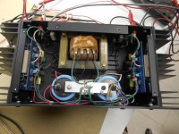
I came across a Belles Two Stereo Power Amplifier with a blown line fuse. I can't find a schematic but my guess is the four T03 devices on each heat sink appear to be a (cascode) arrangement rather than paralled. One of the final outputs was shorted. After replacing that T03, all was good.....I thought.
As with the Amber 70 amp I have been struggling with, there is a low level hum when both channels are connected. The Belles amp is quiet if nothing is connected to the RCA inputs and quiet if only one channel at a time is connected. This is the case even when a battery powered mp3 player is the source. (no possible ground loop other than between the inputs themselves) The two channels just don't get along with each other!
The RCA input jacks are isolated from the chassis. I have inserted a 10 ohm resistor between the RCA shells and the connection inside the amp. No effect.
Thanks again for everyone's help, Peter in Canada
Attachments
Sounds like a cross channel ground loop. Adding the 10 Ohm resistor in series with the signal return in the amp is unlikely to help, but make no difference, or make it worse.
Question: If you put the lid on the amp and screw it down, is there a change in the noise?
Since this is a commercial product, I would expect it would originally not have this problem - maybe someone who is familiar with this amp can verify.
Question: If you put the lid on the amp and screw it down, is there a change in the noise?
Since this is a commercial product, I would expect it would originally not have this problem - maybe someone who is familiar with this amp can verify.
Thanks Bonsai. The lid made no difference. With one input connected, there is hum when the shell of the other channel cable is touched to the RCA input jack. I am guessing that the grounds of the two inputs are at slightly different potential....but it is a hum potential, not a DC difference, maybe a bad cap on one channel driver board?
This amp could have been like this when new, hum is beyond any reasonable S/N ratio.
This amp could have been like this when new, hum is beyond any reasonable S/N ratio.
Thanks, I meant to say; This amp could NOT have been like this when new.
With nothing connected to the inputs, there is 5 mV P to P hum. With a single RCA cable connected from one input to the other, the hum is the same.
With the left ground (signal return) lifted from the RCA jack shell inside the amp, the hum is much worse on the left.
With RCA "shorting plugs" installed in each input, the hum level an acceptable 2 mV P to P. I have to get within 6" of very efficient speakers to detect it. I do not have a schematic for the amp but there are only 3 electrolytics on each driver board. Could they be suspects? They look OK visually. The main power supply caps have 0.25 Volts ripple P to P. I paralleled them with 9800 ufd caps and found no change.
Hi Peter
The basic wiring of the amplifier is the problem. The HUM problem is the poor grounding. Stereo power amplifiers need to have a ZERO node inputs & outputs. Have you looked @ a BGW 250, 750 and seen the way I resolved the issue? You can add a small 1:1 TX on one of the RCA input and this should resolve the hum or rewire the grounding scheme.
Duke
It probably does not mean anything but the wiring of the transformer to the Graetz bridge and common GND is odd 🙂
Some observations and questions:
1. you should not replace not just 1 power transistor (normally, if stuff needs to be AOK)
2. what is the idle current of each channel?
3. how are the main filter caps with regards to value?
4. the screws of the main filter caps should not be steel ones. 1 isn't and the other 3 are ferro. Replace and add tooth lock washers.
5. is the casing connected to PE?
6. does moving the input wiring farther away from the transformer make a difference? The wiring for Left is very close to the transformer.... Drill 2 holes 20 mm from the cooling vents (so below the black electrolytic caps) and add cable holders for L/R.
7. changing the input wiring for shielded wire seems a good idea. Still, the farther away from the transformer the better. See #6.
8. recapping also seems a good idea. It probably was done already a long time ago but redoing that wouldn't hurt.
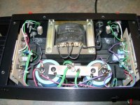
I added a picture of the same amp as found on the web. Wiring seems different.
Some observations and questions:
1. you should not replace not just 1 power transistor (normally, if stuff needs to be AOK)
2. what is the idle current of each channel?
3. how are the main filter caps with regards to value?
4. the screws of the main filter caps should not be steel ones. 1 isn't and the other 3 are ferro. Replace and add tooth lock washers.
5. is the casing connected to PE?
6. does moving the input wiring farther away from the transformer make a difference? The wiring for Left is very close to the transformer.... Drill 2 holes 20 mm from the cooling vents (so below the black electrolytic caps) and add cable holders for L/R.
7. changing the input wiring for shielded wire seems a good idea. Still, the farther away from the transformer the better. See #6.
8. recapping also seems a good idea. It probably was done already a long time ago but redoing that wouldn't hurt.
I added a picture of the same amp as found on the web. Wiring seems different.
Attachments
Last edited:
That wiring to the main capacitors, they don't look original. And what about the twisted input wires, I'd replace them with shielded cable. Or just move them farther from the mains transformer.
Thanks Duke;
I can understand that a transformer would stop the ground loop but I want to find the cause of the ground loop. I can't believe the amp was like this from the factory. Can you explain "ZERO node input's and outputs"? Pardon my ignorance. The amp seems to observe 'star topology'. I will have to look at a BGW 750 schematic.
Thanks Jean-Paul;
I understand that paralleled outputs should be matched for current sharring reasons but the outputs are not parralled, it is a cascode design from what I gather I have loosened the cap screws and retightened. I do not have a capacitance meter but I added 9800 ufd to each filter cap with zero change in hum level.
Thanks also for thTe dpic of the other amphave moved the input wiring and that doesn't affect the hum either.
Alway replace complete sets of power transistors (and in both channels) that is what is taught to me. These all age and the new one will differ too much, maybe being from a different brand even, making it a shitty job from a quality/technical/soundwise point of view when replacing just 1.
You missed some other remarks and I made it easy by numbering them 🙂 That is a somewhat logical approach to issues. I will add a few:
9. triggered by the clever comment of Audio1Man I think you better use shielded cable to the PCB's but don't connect the shields at the RCA connector side. Isolate them there. Then connect a wire from each RCA GND lug to the audio GND point. I think it is solved then.
10. when things are Ok again make wiring tidy en preferably use somewhat thicker wire, recap the poor thing as costs are low (at least the electrolytic caps on the boards), replace all power transistors that are pairs.
It would help you when you would reply to suggestions and answer questions as it is your issue not ours 😀
Last edited:
Thanks again, Jean-Paul;
I will address all 10 points but you have solved the problem with point #6 !!!
I thought for sure that I had tried moving the twisted input wires but I have now completely tucked them beside the pcb and thhe hum is almost completely gone. As suggested, shielded cable would be the way to go.
Thank you so much!
I would still like to know what Zero node inputs and outputs are...
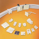
Good! Then still add cable holders or whatever these are called (those plastic lugs to keep cabling at a certain place) as the input wiring may come loose again creating the same issue making you or someone else having to look again to solve this issue. 2 x 3.5 mm holes, 2 x plastic cable holders, 2 x M3 bolts and nuts and 2 x M3 washers and there will be a permanent reduction of the hum pickup. Of course you will still be able to measure hum, therefor the shielded cable would only add up to already improved results. In the world all solutions are equal but some solutions are more equal than others.
Don't say "duct tape" 🙂
(I see these are called "wire fasteners")
Don't say "duct tape" 🙂
(I see these are called "wire fasteners")
Attachments
Last edited:
Hi Peter
Look @ the grounding, and bussing of CT of large filters and the connecting to the bussing of the speaker loads and inputs.
duke.aguiar@ieee.org
Look @ the grounding, and bussing of CT of large filters and the connecting to the bussing of the speaker loads and inputs.
duke.aguiar@ieee.org
Attachments
- Home
- Amplifiers
- Solid State
- Hell's Belles (Two) Ground Loop Hum