FS: CUE-838

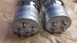
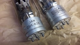
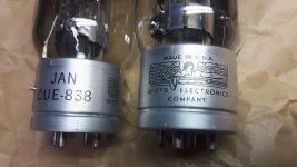
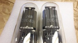
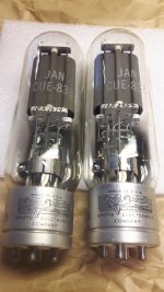
A pair of gorgeous JAN CUE-838. I have no idea what to expect for these. I see fantasy prices on ebay, but I don't really like ebay...

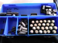
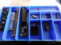
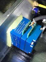
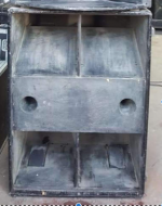
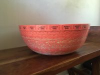
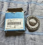
These were in a military wooden box which has been sitting in storage since WW2. The box and paper wrappings were pretty rotten, so now they are wrapped in fresh paper.

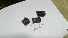
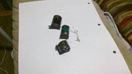
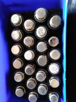
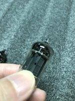
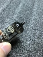
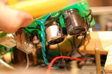
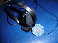
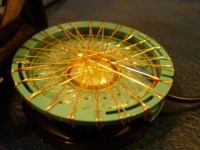
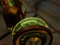
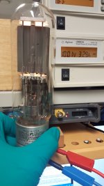
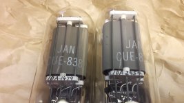
I do not know their condition. The getter looks good, pretty generous amounts of getter. The plates on one of them is slightly darker than the other, perhaps indicating some use...? See pictures.

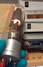
The filaments look good and draw the correct amount of power.

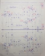
Datasheets here: TDSL Tube data [838]

Please try me with an offer. Will consider trade with a pair of good FR drivers (preferably > 6") and/or some decent OPT (shipping cost may become an issue so we'd have to work something out).

Located in Norway.
Thanks

Attachments

  • 1479_1.jpg
    1479_1.jpg
    222.4 KB · Views: 119
  • 2454_1.jpg
    2454_1.jpg
    225 KB · Views: 117
  • 20210405_210645.jpg
    20210405_210645.jpg
    482.3 KB · Views: 122
  • 20210405_210701.jpg
    20210405_210701.jpg
    203.5 KB · Views: 109
  • 20210405_210737.jpg
    20210405_210737.jpg
    219.5 KB · Views: 109
  • 20210405_210758.jpg
    20210405_210758.jpg
    309.2 KB · Views: 69
  • 20210405_210917.jpg
    20210405_210917.jpg
    701.2 KB · Views: 58
  • 20210405_210935.jpg
    20210405_210935.jpg
    645.3 KB · Views: 59
  • 20210405_210855.jpg
    20210405_210855.jpg
    446.1 KB · Views: 57
  • 1479_3.jpg
    1479_3.jpg
    129.5 KB · Views: 64

Magnet interaction with mmc20en

As some of you might know i start building a tonearm especially for this cartridge i have from a disabled beogram 2202.During my trials i found that i could use a magnet for helping me attach the cart to the arm . At first i tried a small disk 3.5/ mm diameter magnet and then i wanted to try some more powerfull one , made out of two magnets from a dvd optical pickup, almost the same size as the back cut of the cartridge and 5 mm thick .
Given the internal geometry of MMC carts which is not entirely clear to me, but looks almost like it has a magnet placed at the back, how would you think my external magnet placed at the back of the cartridge be affecting the cart's specs? I tried to get an answer on this on beoworld site, but it looks like nobody's tuned into my curiosity...Most probably what we see at the back of the cart isn't the cart's magnet so if it's the metal closing the magnetic circuit, my magnets won't be able to interact with the cart's magnet field, but even if it does how will it do it?Will it decrease the cart's magnet field or increase it?
Unfortunately i am not allowed for the moment to upload any images on the site...I have no idea why.

Alpair Pensil 10p Build - and Questions

This is my second speaker build. My first was a set of Dallas II cabs I documented here :

https://www.diyaudio.com/forums/full-range/318518-dallas-ii-build.html

My wife felt pretty strongly that she wanted something with a smaller footprint in the living room, so I'm building the Pensils and the Frugel Horn XL and seeing which ones get the upvote. I'm going to have fun with it.

This promises to be an easier build, but as a trade-off, I plan on being more detail-oriented with this one. I broke down the stock over the weekend into roughly what all the panels will need to be (pics later).

In order to make the speaker as adjustable as possible, I'd like to be able to easily remove the driver and the back panel - and in the interest of durability, I was thinking of using machine screws/bolts and threaded inserts directly into the wood. These usually come in some kind of metal. For the back, I'll use some kind of neoprene along the edge to seal it up and avoid vibration. The driver gasket will do the same thing along the front. Are there any issues acoustically with using these metal inserts?

Second - I've decided for now to forgo the side to side bracing, which the designer says are not needed for the (smaller than 12p) pensils. Anyone have thoughts?

Third - I'm considering a double thickness baffle for the front, but the trade-off is that with double 19mm plywood, I either end up with a deeper inset (which I guess I can chamfer) or I end up with a lot of thickness behind the driver frame (which I can also chamfer). Any pros or cons here?

Looking for help repairing PPI PC450

Hello,

I recently installed my old PC450 amplifier into a new car. I had this amplifier for years with no issues.

In the new car I immediately noticed the amp got very hot and stopped outputting. I did not have an inline fuse installed.

I powered up with a current limited supply and found the output transistors were getting very hot. I removed them from the board and checked for shorts but found none. I replaced anyway and still have the same problem with new fets.

The amplifier powers up normal drawing normal current then after about 30 seconds it draws max current limit from the supply (5A) and all outputs get hot for all 4 channels.

Currently only the outputs for CH1 are on the board and the problem still occurs.

Any help would be greatly appreciated!😀

Help biasing Pioneer SA-8500II Phono stage

I installed new transistors in the AWF-023 Equalizer Amplifier board on the Pioneer SA8500II amp. I used the KSA992s and KSC1845s. The voltages on Q9 and Q10 are off a little and I wasn't sure if I need to change any of the bias resistor values? Also the current is at 4.1ma instead of 3.5ma. Not sure if it's off enough to matter? I have all the voltages marked on the schematic. Sorry the schematic is a little light.

Kennyg

Attachments

  • 20210403_120951.jpg
    20210403_120951.jpg
    411 KB · Views: 108

Best speaker kit for smallish living room? (13x9x8)

Hey everyone,

Long time lurker here. Always blown away by the wonderful builds you all post!

I'm looking to build another set of speakers to celebrate a career milestone. However, a lot of the science-y stuff I've read is a bit over my head. I hear all sorts of different (and great) insights here on builds and I was wondering if anyone could guide me a bit better in my research toward my next set of speakers. 🙂

This is more of a speaker question than a room acoustic question: Unfortunately, I'm pretty tight on space (see pics) so paneling, while I know makes good kits into amazing kits, isn't really an option as far as I've seen.

Current Setup: AviaTrix MTM powered by an SMSL SA-98E (160 watt x 2) amplifier. Source is a HiFiBerry DAC+.
What I'm Looking For: Honestly, I absolutely love the sound of these speakers! I only really wish they had a bit more bass. So merely remedying this is an option as well 🙂

Room Size: ~13'x9'x8' LWH
Room Details: Next to kitchen (left) and large window (right). Only (audiophile) upstairs neighbor; no walls shared with any neighbors
Speaker Distance from Listener: ~13'
Budget: ~$2000* (not including amplifier)
Build Preferences: Premade or pre-cut cabinets / full kits. I can veneer, though I'm not averse to pre-finished / repurposed cabinets
Tools: Electronics workstation (Hakko digital soldering iron). No woodworking tools nor experience past veneering and maker places in my city are indefinitely shut due to Covid 🙁

*Price is flexible; by no means does it reflect what I need to spend, just an upper limit of what I'm comfortable spending. Lower priced kits absolutely are encouraged 🙂

Pictures of room (with dimensions) here:
Imgur: The magic of the Internet

Any help would be greatly appreciated. Thanks in advance 🙂

Philco 9200 tube tester always indicates cathode shorts

I love the aesthetics and build quality of my Philco 9200 tube tester.
It's a fine example of functional industrial art IMO. It's so steampunk it has a scroll, not that it is any different from any other tube tester. At the hart of the tester is a transformer with 18 different secondary taps!

Anyway, I made the mistake of spraying the switches and tube contacts with Deoxit. It now indicates filament leakage no matter what tube I put in. I hypothesize there's some current leakage going on due to pools of deoxit at tube socket sites.

Is this a feasible explanation?
I assume Deoxit conducts electricity to a degree?

If I could isolate the tube sockets completely I'd stand a better chance of chasing down the leakage. Unfortunately, there is no switch position that does that. Impedance back through the transformer secondary's makes this a Thevenin parallel path nightmare with the power off so it's difficult to obtain any useful info using an ohm meter.

I think I might just remove the scroll and submerge the entire circuitry in a pan of alcohol, swish around, let dry, and retest. it's virtually impossible to get even a q-tip between socket pins with all the wiring present.

I thoroughly understand the circuit now. I've made neon bulb voltage measurements during the tests which line up with what I am seeing.

Any other suggestions?

Attachments

FS: some miro1360 DAC AD1862 PCBs

Hi folks,

got some PCBs for miro1360's DAC AD1862.
I ordered more than I need, so I have 8 pieces left.
newest PCB version: diyAudio_AD1862_DAC_v1.3_pad_PPY3_2021-01-14

Price for each is 2,50€.

I try to keep shipping costs as low as possible:

Germany: 1 PCB 0,95€, >1 PCBs 1,55€ unregistered
for registered mail please add 2,20€

World: 1 PCB 1,70€, >1 PCBs 3,15€ unregistered
for registered mail please add 3,50€

hurry up now 🙂

Greetings,
Ralf

Attachments

  • IMG_20210324_162630.jpg
    IMG_20210324_162630.jpg
    430.9 KB · Views: 217
  • IMG_20210324_162700.jpg
    IMG_20210324_162700.jpg
    258.4 KB · Views: 210
  • IMG_20210324_162901.jpg
    IMG_20210324_162901.jpg
    604.1 KB · Views: 202

Battery board for 2.1 amp

Hi everybody,

I want to build an autonomous transportable bluetooth speaker and I want to use a 2.1 amp, it is the TSA7800B amp from Tinyside. I want to power this amp with batteries and I need quite a big capacity so I found the Wondom BCPB4 battery board that I could use with 5S 26650 batteries. But I don't know if this battery board will be compatible with my amp.

If I want a bigger capacity, do you know another solution that I could use ? I know I could build a battery pack with the right number of batteries in series and parallel to reach the desirable voltage and capacity, but I would have to use a BMS to balance the charge of batteries and it scares me as I don't have that much experience in electronics. That's why I would prefer to have a battery board that manages the balance and the charge of batteries, like the BCPB4. Do you have suggestions ?

Thank you very much !

Mr White's "Opus", designing a simple balanced DAC

Hello All,

Some of you may recall that a while back I was designing a balanced DAC around a Wavefront chip. I still have that design and I still like it. But in some ways it just was not really what I wanted. I wanted to be able to accept I2S in and I wanted the higher bandwidth of a better chip. Someone, I think Craig, suggested a look at the Wolfson line of DACs. That was a good suggestion.

After a bit of googling I could see that Wolfson made some very highly regarded DACs. They are used in products such as Arcam with very good reputations.

I looked in particular at the WM8740 which has everything I am looking for. It is a 24-bit 192KHz DAC with balanced stereo output and when used in stereo mode (to keep it simple) it has a 117db SNR. It has a pretty simple hardware interface with no need for a micro-controller to get the thing to work. Nice and simple, just the way I like it.

This is really a continuation of my efforts from the Wavefront DAC, so it is in reality my very first DAC project. I want it to be a community project. I want to share what I am learning with all of the others on the forum who may have a chance to apply the techniques to their own projects.

I will be publishing schematics as I go so that I can get critiques on the ideas I propose and I can get a clue on whether what I propose will even work in the first place.

Now let me lay out some design goals so that we donot go off on too many rabbit trails.

1)The DAC PCB will be just a DAC with a Receiver and an optional TORX Receiver which can be omitted.
2)Digital input will be S/PDIF or I2S.
3)There will be no output stage on the DAC PCB itself as I want that to be separate since in practice there are many ways to execute it. My idea is to design one filtering output circuit which will stack with the DAC. You could actually go directly from the DAC circuit to a balanced preamp, but without any analog output signal filtering.
4)The PCB for the circuit will be designed to be small so that stacking modules will be very easy and integration with other projects will be simpler. One module idea I have for the future is to create a USB input circuit which would feed an I2S stream direct to the DAC with no S/PDIF conversion in the process.
5)I want to keep the circuit SIMPLE. That is key. I want to avoid using external clocks and such, at least for the first version. There will be future revisions which may include such features. But it is an explicit design goal of the first version to only utilize the WM8740s internal PLL.

Now some requests for help on areas I am not sure of.

1)Does my S/PDIF input scheme look sane? Can I do it better?
2)I wanted to keep the digital power supply simple at 5V only, so I chose the CS8414 but would it better to use the CS8416? If so why?
3)I would be very grateful if someone could take a closer look at my reset scheme for the receiver and the DAC. Does it look workable? Particularly I wonder about the choice of the timing capacitor for the voltage supervisor (TLC775).

I have attached my first cut at the schematic for the DAC circuit. Please forgive that it is not very polished. Some value are missing or have yet to be determined, but it should give you insight into what I have planned.

Thanks for looking and for all who have expressed interest so far. I hope everyone can use the information that comes from the project.

Cheers!
Russ

Attachments

  • schem.png
    schem.png
    16.2 KB · Views: 23,624

Alignment 10.7MHz IF strip

Screenshot from 2021-03-14 11-53-44.png


I am building a kit at the moment, and trying to align the IF strip. I've put 10.7MHz into the grid of G2B and working my way along. There are two ferrite slugs for each transformer. T1, T2 and T3 align fine. When I get to T4 there is no signal. I know this is a limiter stage, but the plate of G5 is only at 16V and the screen 48V. This does not look correct. The resistor values look wrong to me. If I remove G5 and connect pin 1 to pin 5 I do get a signal at T4. I could not find a datasheet for 6K4 and 6J4. Any help much appreciated.

bridge rectifier

i am a bit confused, just as i thought i was getting to understand about how these work.
in the picture attached are two diagrams.
figure 1 shows a snap shot of the one in the amp im working on
figure 2 shows, what i assume is a typical set up of one of these guys,


what i am confused about is on figure 1 it shows 2 possitive supplies going to the rectifier, where as figure 2 shows it to be +/- to each of the terminals.


am i looking at this incorrectly, or is it the one on my board isnt doing what i think it is?


when the rectifier is on the board there is a dead short between the + and - legs, but not when it is off the board, as i checked it, so there is obviously something a miss elsewhere which i will have to look for, but i just dont understand the diagram.


many thanks

Attachments

  • rectifier question.jpg
    rectifier question.jpg
    80 KB · Views: 320

Help deciphering crossover schematic

I was hoping to accomplish a few things here.

First I would like to rebuild the crossover so that I could active tri-amp the speaker and keep the HF network intact. (Would I be correct to assume I could just build the section circled in red?)

Also at some later date just for fun I would like to try and duplicate the HF network in a DSP. What driver information would I need to understand what is being done to each set of drivers in the HF section?

An externally hosted image should be here but it was not working when we last tested it.


An externally hosted image should be here but it was not working when we last tested it.


An externally hosted image should be here but it was not working when we last tested it.


An externally hosted image should be here but it was not working when we last tested it.

Pierre Etienne Leon Integrale speakers. Help!

For reasons I won't go in to due to embarrassment, let's say that the combination of a couple of beer with a buddy, a Santana album and djembe drums spelled disaster for my 90s era PE Leons. A resistor in one crossover had burned and after taking the crossovers to a local shop for repair, the speakers have not sounded the same since. All crossover parts have been replaced with identical to original, though I am not sure that they were wired correctly. Some years ago the manufacturer sent a schematic for similar speaker he makes (why not my speaker I'm not sure) to the distributor here in Canada (who has sadly since gone out of business) who forwarded the schematic on to me. Wired as per that diagram but no luck. All drivers are in good working order.

Does anyone know these speakers or someone who owns them? Need to know how they are wired inside. PE Leon won't reply to my email/phone messages. Guess the $5000 I spent for them entitled me to listen to them but nothing else.

Thanks in advance for your help,

Perry

Would this work well?

IMG_1851.jpg

I have built the power stage of a single ended amp in an enclosure. It’s difficult to fit anymore stuffs in it, so the input stage has to be built separately.

While contemplating an appropriate input stage, I have a DIY single ended a headphone amplifier with a 10k:50 ohm OPT.

I am assuming the EL84 can handle the capacitance of RCA cable and the input capacitance of 300B. But I really don’t know the calculation involves so this is where you guys comes in.

If this will work well. What value of resistor should I put across the secondaries of 10k:50ohms OPT? 50 ohms? 100ohms?

Thanks for reading.

FS LXmini and MiniDSP

Working on a new speakers and need to sell my LXminis. Built in 2015 using a Madisound kit with drivers specified by Siegfried Linkwitz. Build quality is average. $450.

Sale does not include the LXStudio woofers or cabinet. 😀

MiniDSP 2x4 (not the HD) also available for $50. [NO LONGER AVAILABLE.]

Local pick-up (Atlanta metro) preferred but will consider shipping at the buyer's expense.

Attachments

  • IMG_0376.jpeg
    IMG_0376.jpeg
    262 KB · Views: 252

Newbie question: using a primary winding as a secondary

I think I can do this, but thought I should ask... All Antek power torroids come with two 115v primary windings. Id like to use one of those primaries as a 1:1 secondary, as well as using all the other secondaries as normal secondaries. This shouldn't be a problem right? After all they are all wound around the same core.

Random example but all Anteks have the same two primaries:

https://www.antekinc.com/content/AS-3435.pdf

The specs say to wire the primaries in series or parallel depending on your line voltage, but in the USA at least cannot the extra primary be a secondary?

Soundstream Reference 300sx

Hi picked up this very clean ss reference 300sx today. It’s got a modified power supply section, and came with a re-birth sheet attached. Does anybody have a schematic so I can just kind of check this one over parts comparison from original? This Amps seems to have different bridge/rect diodes possibly different fets different caps than original. And the rail voltage runs +\- 28 in high power, +-22.5 in high current mode. Otherwise it works thus far.

Thank you

Attachments

  • C31065EC-22A9-4DFB-8C45-05E0A744A3D3.jpeg
    C31065EC-22A9-4DFB-8C45-05E0A744A3D3.jpeg
    62.5 KB · Views: 235

Mullard 1955 heated cathode amp

3W Single Ended Class-A Stereo Tube Amplifier – HEATED CATHODE

Does anyone have any knowledge or experience with this amp or design?
Im a newbie learning all I can and this looks very interesting to me.
I have an office desktop (very nearfield and dont listen loudly) system currently with a Naim Unitiqute driving some Harbeth P3esr. However Id like to build myself a cool small footprint tube amp, not sure if 3 watts is enough.
I also do like the EL 84 tube.
Any thoughts?
Thanks

Make a 10k pot out of a 100k pot?

I have a little headphone amp project going on that I'd like to try with a 10k-log pot as the volume control.

All I have are 50k-log and 100k-log pots.

I was thinking that if I take a 12k resistor and connect it from the top to bottom lugs of the pot (pins 1 and 3), that will put that 12k ohms in parallel with the 100k ohms of the pot, which should end up making the pot value 10.7k ohms (close enough).

However, I've read that the output impedance of the pot (used as a volume control) won't change if I do that. Huh??

I figure the wiper is moving on the carbon (or resistive plastic) track, and will always be in parallel with the Rparallel (12k) between the pot's pins 1 and 3. It should act pretty much exactly like a (nearly) 10k ohm pot.

No? Now what piece of elementary electronics am I missing?

😕

Headphone Tube Amp buzzing and Humming how to fix?

Hello

I hear Buzzing and Humming from my WA 2 HPA when my desktop dac Burson Conductor C3(2V Line Out) is connected, can anyone tell me where this noise coming from and how do I eliminate it?

also I emailed Burson Audio and Woo Audio, and B told me on that it might be impedance matching issue.

And WA Told me that it's normal to hear Hum/Buz at High Volume.(which doesn't makes sense)

Please advise what i can do to fix it

replace selenium rectifier philips ag9016

Hi all.
I want to replace the rectifier for diodes.
The plate/anode voltage on the EL95 is 252vdc
And 240vdc on cathode.
Will the El95 be ok with the increase in voltage after the change if not what sort of value resistor would I need .
Thanks

Attachments

Naim CDi servo board problem

Hello everyone I've just bought a Naim CDi with issues (that how the previous owner described it). Up on powering the unit up I noticed the motor spins immediately and fairly fast CCW, it just spins and spins no matter what I press, with or without CD. The laser tried to focus and stay in inner-center position but the warp speed made it chucked out an error.

Further inspection revealed that for some reasons someone tried to scratched out two electrical traces. One of the traces leads to the 220uf caps the other leads to the lid switch-connector and the red wire that goes to the collector of transistor 8c338. Right now I have reconnected the traces with solder wires (temp fix) and fired it up. The speed is the same but this time the laser goes all the way out to the edge and stays there and no focus whatsoever. To put insults to injuries I think I smelled that beautiful electrical fume coming out from one of those 220uf caps 🙁

I'm not sure what I should do next..any help is greatly appreciated.
Aaron

Edit: The schematic show where the traces are cut and the positions of the 220uf caps.

IMG_1631_zpsvmdj3rwa.jpg


servo_zpsb2qhhfml.png


IMG_1634_zpsehexbrwt.jpg

A box of old Opamps

I've had a box of old Opamps I was kindly given to me a while ago, along with an old Weller soldering iron, lots of solder and an Beckman DMM from the early 80s.

I got them from a retired tech

Are the old can Opamps any good?

Attachments

  • 16175263266858515613817468881148.jpg
    16175263266858515613817468881148.jpg
    573.2 KB · Views: 295
  • 1617526389612186726816918757162.jpg
    1617526389612186726816918757162.jpg
    445.9 KB · Views: 270
  • 16175264320363822733745577308347.jpg
    16175264320363822733745577308347.jpg
    582.1 KB · Views: 278

Hearing High Frequencies “When I’m 64”

The Beatles song “When I’m 64” was originally written by Paul McCartney in 1956, the year I was born. I turned 64 this year, so did my partner who learned to play the song for her birthday.

The song opens with: “When I get older, losing my hair”.
Having heard the line many times since it’s 1967 release, never thought about how it also applies to our hearing until recently.
Age-related hearing loss (presbycusis) and noise induced hearing loss (NIHL) literally result from the loss of inner ear hair cells.
High frequencies (HF) usually are the first to go, though NIHL also may cause a dip in hearing in the 4kHz (4000 cycles per second) range, where we are (were..) most sensitive to hearing.

By the age of 64 the average person has lost near 40dB at 4kHz, 50 dB at 8kHz, and hearing is more or less “gone” above 10kHz. Younger people can use 10kHz “mosquito” ringtones that most of us over 60 won’t hear.
My 64 year old partner has almost no presbycusis, she hears better than most people less than half her age. On the other side of the hearing loss coin toss, mine is more like someone almost 20 years older.

So what can the DIY person do about presbycusis?

1) Delay and reduce the problem before it happens, WEAR HEARING PROTECTION!
Although eye protection and dust masks were provided in school shop classes, hearing protection was not, even in firearm training. I had built several complete PA systems and toured the USA with them providing concert sound in theaters and arenas before first regularly wearing hearing protection around power tools in 1979. By then, NIHL had already begun, but testing my father’s hearing along side mine in 1998 was scary, realizing that on top of the 4kHz NIHL I could look forward to presbycusis.
Unfortunately for many of us, we used hearing protection too little, too late, which requires another solution:

2) Aquire good hearing aids fitted by a good audiologist.
I found an audiologist that sold, and was experienced fitting the various hearing aid manufacturer’s models I had under consideration. Although you might not think of hearing aids as “DIY Audio” they most certainly are- no other audio investment will be more “yourself” orientated than personal amplification.
I did more research into hearing aids prior to purchase than for any other devices bought as a professional sound engineer during my entire adult life.

Arthur C. Clarke wrote: “Any sufficiently advanced technology is equivalent to magic.” Hearing aid technology has advanced enough that their capabilities do seem “magical” in comparison to what was available previously.

After purchase, I measured the Phonak Audeo P-90 latency at only 6.15ms with all features engaged. The P-90 is a behind the ear “receiver in canal” (RIC) design, the RIC in the ear canal does not obstruct normal hearing, the receiver is a tiny balanced armature driver. “Magically”, the latency does not cause any audible comb filter effects I would expect between my normal hearing and the amplified sound through the receiver. The latency allows enough time for the automatic programs to choose how much speech or music components are amplified by frequency and level, or if determined to be noise, their reduction or cancellation.
The two hearing aids are wirelessly interconnected, allowing for implementation of the algorithms that automatically and adaptively adjust response and microphone configuration to different hearing environments and noise, those responses set by preference during fitting.

After two months of hearing aid use, find they make hearing similar to 20 years ago, hearing details again that had slowly faded over the years. I can again understand lyrics without cranking up the level, hear brushes on drums, fret noises, and room reverb sounds that had gone missing.
Although the missing high frequency detail is back, not experiencing any “too loud” sensation when SPL increases above the 65-70 dB SPL (sound pressure level) “conversational level” I usually listen at, even dumping bottles into the recycling bin sounds no worse than it did before.

The sound with the aids is still far from perfect, but the improvement is dramatic enough that I wear them nearly all my waking hours.
Another deciding factor in wearing them is that along with NIHL and presbycusis, my tinnitus (“ringing” in the ears) had increased to a level where it masked (sounded louder) than the high frequency of music or speech at conversational levels. Although hearing aids can’t reduce tinnitus, with background music playing I now hear it, rather than the ringing.

My audiogram and fitting report for the P-90s are attached, along with an explanation of what an audiogram means in dB SPL (Sound Pressure Level) compared to dB HL (hearing loss).

On the audiogram, the lower line with the “m”-like symbols indicate the loudness discomfort level (LDL), the intensity of sound at which a patient reports sound to be uncomfortably loud. The LDL is measured to determine the patient's dynamic range of hearing, the range from the softest to the loudest sound they can tolerate without discomfort. The purpose of determining the patient's dynamic range is to ensure that the hearing aid amplification remains within the comfortable levels of the listener.

Hope the above helps anyone who has been thinking about their hearing!

Art

Attachments

  • Art's L:R Fitting Report .jpg
    Art's L:R Fitting Report .jpg
    74.7 KB · Views: 559
  • dBSPL & Audiogram dBHL.png
    dBSPL & Audiogram dBHL.png
    836.4 KB · Views: 536

Purpose-built Boominator PCB project

UPDATE:

The "cAMP" purpose-built Boominator amplifier will be available soon from Canopy Sound!

http://canopysound.dk/da/camp-standard


--- rest of thread is a historical design blab and can safely be ignored... ---

Saturnus's Boominator project is awfully nice, and I'm currently working on a smaller version of it to use as a solar powered camping stereo.

I've decided to make my own custom PCB for running it, with features that would be hard, impossible or impractical to do by combining pre-bought pieces. It will provide the following:

- Class D amplification for playing music from MP3 players, cellphones, CD players, etc.
- MPPT-tracking, solar battery charger. Set up for 12V SLA batteries in my application, but capable of doing lithium ion with resistor changes.
- Able to charge from an external AC adapter also.
- Battery protection. Everything shuts off if the battery gets too low.
- A 5V USB port or two for charging phones, MP3 players, etc.

The audio section will consist of:

- A stereo audio receiver that's tolerant of ground loops, so you can charge the device you're playing audio from without hearing charging noise.
- An Analog Devices SigmaDSP chip. This will perform volume control with a pot acting as a volume knob, equalization, noise gating, bass/stereo enhancement, crossovers for bi-amping, any number of other things to make the stereo sound better.
- Four total class D amplifier channels, each set up for driving 4 ohms, but capable of 8 ohms with inductor/capacitor changes. I'm planning to bi-amp the woofers/tweeters in my stereo, but you could use external crossovers instead and double the output power.

Right now I'm nailing down the parts list, mechanical form factor, etc. I'm designing this project in Eagle, and I'll share the design files under a CC license when it's done.

I won't say "group buy" just yet, but if enough people are interested in such a thing when the design is done, it could be arranged. Right now, this thread is intended to be a design log more than anything.

Figuring out reason for various resistor values on Potentiometer circuits

I have been trying to figure out the reasoning over the resistor arrangement for these 10 potentiometer circuits. All these circuits basically have the same resistor arrangement , and all values are different , except for 2 which are the 1.5K and the 6K resistor values. I totally understand the reasoning for the 1.5K resistor in parallel on the potentiometer output which are for to convert linear Pot to a more log output. The other resistor values I have no idea why its like that.

The history of these 10 circuits, is these are the real key circuits for the 1939 Bell labs voder. Which is a speech synthesizer that is manually controlled using 10 keys with various other circuits.

I did check all of these circuits in spice and the output voltages are different due to different resistor values. My only guess is why the resistors are different for each key is for some type of equalization?

keys1.jpg

Need some help setting up Raspberry pi with volumio

I have a rasberry pi 4B.
I put Volumio onto a mini mem card.
Where the trouble lies is: I can not figure out how to set up a windows share that Volumio will see and like. This is for music. I Have a 64 gig USB card I would like to use. Or I have a 1T usb drive I would rather use. Which ever will work.
If someone can hold my hand thru this it would be appreciated. Also Ihave a topping D50S DAC. it is not in the list of I2S dacs that volumio shows you but everywhere says its supported so do I use the generic I2S drop down pick?
And if you leave instructions PLEASE do not assume I know my way around a raspberry pi. I do not. Nor do I know linux.

Thank you SO VERY much!

Jeff

DIY Marantz M7 using 6SN7 and 6SL7

This is a modified Marantz M7 circuit design using 6SN7 and 6SL7, but still can use ECC83. What makes this circuit so special is the use of DB3 at output, so what's the use of that? I will let you all guess😀

Attachments

  • M7 Power.pdf
    M7 Power.pdf
    13.5 KB · Views: 295
  • M7.pdf
    M7.pdf
    15.2 KB · Views: 387
  • 3ce49834-d5be-4df5-9f1f-161f4e5373ca.jpg
    3ce49834-d5be-4df5-9f1f-161f4e5373ca.jpg
    107.3 KB · Views: 954
  • 4dbef2a3-ca2d-411a-9c57-fbf05ddb4c69.jpg
    4dbef2a3-ca2d-411a-9c57-fbf05ddb4c69.jpg
    106.6 KB · Views: 952
  • 489b8fcf-1506-439d-ae44-c5ceab624158.jpg
    489b8fcf-1506-439d-ae44-c5ceab624158.jpg
    112.9 KB · Views: 929
  • f809f4a8-7eb9-4242-9bc8-55f18a77037e.jpg
    f809f4a8-7eb9-4242-9bc8-55f18a77037e.jpg
    163 KB · Views: 920
  • d3946125-b96c-4dcc-a5b6-e7e620d673a0.jpg
    d3946125-b96c-4dcc-a5b6-e7e620d673a0.jpg
    188 KB · Views: 933
  • 75600514-390b-4107-8d0a-8293fbe5a667.jpg
    75600514-390b-4107-8d0a-8293fbe5a667.jpg
    124.8 KB · Views: 369
  • ccd9a2dd-f81d-4a7f-bb91-b4c5603d3c1c.jpg
    ccd9a2dd-f81d-4a7f-bb91-b4c5603d3c1c.jpg
    118.5 KB · Views: 362
  • a5ef2327-3d6e-4f07-80a0-725b32f9d290.jpg
    a5ef2327-3d6e-4f07-80a0-725b32f9d290.jpg
    126.4 KB · Views: 463

Automatic Image Display

I have a simple question, but I cannot find an obvious answer.
When viewing posts, the images are not automatically displayed and require clicking on every time.

Is there a way round this, so that at least the a small button of the image is automatically visible before clicking to enlarge ?


Many Thanks in advance,
XACOO

Attachments

  • Image Display.png
    Image Display.png
    13 KB · Views: 123

Theoretical TS question regarding horn drivers

Hi All,

I'm currently running an EVM15L driver on a front loaded horn. I've been toying with swapping to a pair of 10's instead. If I had a list of TS specs in front of me which ones would change between the 10 and the 15 ? I know SD, xmax possibly, but am not sure of the rest.

Basically I'm trying to source a pair of 10's that have a combined TS spec equal to the EVM15L on the same horn.

Thanks,
Rob.

Super tweeter to FANE 12-250

My speakers are filtered FANE SOVEREIGN 12-250 in a sealed box. First build, very enjoyable so far. As an experiment, I have bought a pair of cheap GRS BTR3-8 bullet tweeters. My aims are to reduce beaming and to add a little bit of air to the top end. But most of all to learn along the way.
Please, find atttached, a couple of measurements I have made with a 47uF capacitor in series with the tweeter. On axis and 30 degress off @ 1.1m. The measurements are presented with FR driver measurements respectively at the same distances and angles.

I would like to get some recommendations on how to proceed further. Should I try to XSIM the response? What should I look for for smooth integration? I have some Wima MKS4 caps 1uF, 0.5 uF, 0.1 uF caps at hand to help me.

Attachments

  • IMG_9089.jpg
    IMG_9089.jpg
    374.4 KB · Views: 146
  • Screenshot 2021-04-05 at 11.34.21.png
    Screenshot 2021-04-05 at 11.34.21.png
    375 KB · Views: 150
  • Screenshot 2021-04-05 at 12.36.21.png
    Screenshot 2021-04-05 at 12.36.21.png
    646.8 KB · Views: 140
  • mano paskutinis.jpg
    mano paskutinis.jpg
    73.7 KB · Views: 139
  • impedance.png
    impedance.png
    20.8 KB · Views: 146

BEL 1001 repair info

I am helping a friend troubleshoot and repair his BEL 1001 Mk I amplifier (he's an original owner!). It's clear that the 2N6284 NPN output transistor in one channel is shorted internally. They are still readily available, but I suspect that there is some matching that needs to be done to preserve performance at the highest level. However, with Richard Brown's passing last October, there appears to be no source of info (schematic, etc.) available. Anyone have any ideas?

Thanks!

FS: Dr Mordor TPA3255 Amp from group buy

Hi, due to forced changes, I would like to transfer my GB purchase of the Dr. Mordor TPA3255. All details in the GB page:

https://www.diyaudio.com/forums/gro...one-amp-based-tpa325x-pffb-llc-psu-board.html

My amp should be shipped this week. The buyer will pay me the cost of the complete amp (I ordered an assembled amp in a case), and will have the amp shipped to him/her instead of myself. For details please contact me in MP.

MDDFL: floorstanding, virtual array, omnidirectional mid-tweeter acoustic load

I spend a lot of time listening to music of all kinds. For my needs, SPL 80-90 dB, in a small room 4 x 4 x 3 meters, my prototypes work fine. As a DIY I've always worked with full-range systems. I use two unconventional acoustic loads at the same time:
- a frontal one (MDDFL) to make the high frequency emission omnidirectional, I think it can be used in multi-way systems,
- a rear one (MDDBL) for medium-low frequencies.

At the moment I don't need to build a multi-way system. I want to report my prototype for an opinion on the use of the MDDFL front loading with midrange and tweeter.

In the MDD3H240 prototype the front acoustic load (MDDFL) is made with 25 aluminum waveguides of increasing length, from 22 to 618 mm, like a virtual array of tweeters. The wave front emitted by the speaker cone is partly sent into the listening room and partly divided between the 25 waveguides. At the end of the waveguide, a spherical wave front is generated which makes the emission omnidirectional at all frequencies.

The drive is located close to the floor and therefore does not generate reflections with it.

Increasing lengths generate delays of between 0.1 and 2 milliseconds. The delay interval of the secondary sound fronts is further dilated by the omnidirectional emission, the number of paths of different lengths in which the sound energy propagates is increased. The possibility of perceiving the precedence effect studied by Haas is reduced. The same sound continues to arrive with increasing delays and not as distinct events that would tire the listening.

Thanks for your attention, I am available to anyone who would like more information.


Claudio Gandolfi - MDD (Multi Delays Diffraction Loudspeaker)
MDD3A89
https://www.diyaudio.com/forums/pla...idirectional-single-drive-17.html#post6599019

Attachments

  • 3hR616.jpg
    3hR616.jpg
    76.5 KB · Views: 271
  • 3hB613.jpg
    3hB613.jpg
    75.3 KB · Views: 277

M. Koster’s "Schadeode" Push-Pull Version?

I was looking at Michael J Koster's 'Schadeode' circuit, as found here:
RE: hybrid - Michael Koster - Tube DIY Asylum

and here:
Tube DIY Asylum

Looks like a fantastic way to use 6L6s.

So I was thinking.... Why not push-pull? I threw it all into spice, and as long as you can match up a couple of DN2540 or 01N100D MOSFETs, the results are nothing short of spectacular. BUT...

How likely is it that matching these MOSFETs would result in a well-balanced push-pull circuit? Would using the two MOSFETs in a LTP with a good stiff CCS in the tail balance them well enough?

I'm wondering why nobody else has posted about this, since it seems an obvious thing to try, and looks so good in simulations.

What do you think?

(Sorry I can't post a schematic. That will have to wait until I get home.)
--

LND150 Depletion MOSFET model

Someone had posted a DMOS model for the LND150 on another forum. I've taken the Supertex info and re-worked it a tiny bit to come up with the following changes to their NMOS Model:

.SUBCKT BVS841_DepletionMosfets__1__5 10 20 30
M1 10 20 30 30 NMOS
.MODEL NMOS NMOS (
+ LEVEL=3
+ NSUB=5.0e13
+ TPG=1
+ CGDO=2.1716e-12
+ RD=400
+ VTO=-1.50
+ VMAX=1.0e8
+ ETA=0.1
+ NFS=6.6e10
+ TOX=1.0e-7
+ LD=1.698e-9
+ UO=862.425
+ XJ=6.467e-7
+ DELTA=0.1
+ THETA=1E-5
+ L=10e-6
+CGSO=5.09e-10
+ W=600e-6
+ KAPPA=1.0
+ )
.ENDS

Attachments

  • LND150.gif
    LND150.gif
    17.4 KB · Views: 967

LC75342

🙂Hi
Has anyone used the LC75342 pre amp/tone board fromYuanJing (China)?
I am building a modified Cooper-Smith 20W amplifier and would like to
use this board as a remote controlled "front end".
The outputs of the preamp board are via 10Uf electrolytics. The input to
the Cooper-Smith is via a 1M potentiometer between input and ground with
the wiper in to a 68k grid stopper feeding a 6SL7 floating paraphase stage.
Can anyone suggest a modification to improve on the signal matching
between the two stages, the Cooper-Smith is set up for a 400mV approx
input level.

Would a Skar ix-8 Work in 3-Way Active Speaker?

I am wanting to build a 3 way active powered speaker for my old roommate. He is a rapper/ producer so he will use heavy bass in his productions. I was thinking of a sealed cabinet to get flat responses from the drivers. Can a 8" car audio subwoofer be used in a monitor? I was thinking of using Dayton RS150P and RST28F with crossover points at 100 Hz and ~1.6 kHz.

Here is the subwoofer's product page. I'm interested because they are very cheap for 2 for $80 on Amazon

Woofer section of 3 way dual mw19p vs 1 wo24

Trying to pair a bass woofer for ja801/sm75-150 classic mid range
Because the tweeter and mid range are closed I can have more cabinet space or probably have the mid and tweeter mount on a narrow open baffle for better imaging
The cross over frequency between the mid and woofer shall be around 400hz.
Would dual mw19p in ML TL cabinet get the benifit of wo24 between 30hz and 100hz region. Or I should pair them with a different woofer

Wiring the Icepower ASP1000

I'm using two ASP1000s as monoblocks. I ordered the Parts Express wiring kits. Since they each have their own power supplies, I won't need ANY of the bus wires. No need to even connect that wire bunch. Am I correct? And lastly, in the signal wires bunch, do I need to ground the green wire to earth, if I'm only using the DC V out, and not necessary for the XLR wires to work? Thank you.

Nakamichi Dac 101??

I just managed to get hold of a nakamichi dac101 12v for cars upon powerup into my home setup was quite suprised possible better than my own dac then music kind of skipped a couple of times and Silence????? dac has to led 48khz and 44.1khs it initially locked onto 44.1 and illuminated led now it flashes if you leave dac down powered for 2hrs it works for half an hour? I think its is a problem with clocks?? not v experienced in dig any one got any ideas???

by the way ps is 13.8 big fully charged lead acid😡

transformer saturation effect

I am working on designing my own guitar amp, and one effect I would like to include is transformer saturation.

I've done as much googling as I can regarding how to achieve this, and there doesn't seem to be a whole lot out there in terms of schematics for my relatively unschooled self.


I came across Triad TY-250P transformers. It looks like they are used in some "transformer saturation color" modules. I am thinking I may use a pair of them, one on each leg of a balanced output (from opamps), then combine the signal afterwards using a differential amp.


My knowledge of transformers (outside of how to build a chipamp PSU) is limited. How would I determine the AC voltage needed to get some saturation as an effect? Also, I'm thinking I need to include a series resistor before the transformers to prevent them from drawing too much current once they reach saturation.


Instead of relying on the signal to saturate the transformer, I could also perhaps bias the signal with some DC?


Has anyone experimented with transformer saturation as an effect, and have any pointers or perhaps schematics?


Thoughts on the TY-250P?


Thanks to all!

Whetever happened to "Utah" speakers?

Been out of the DIY world since the late '70s; life and making a living got in the way.

And somewhere along the line I became (mistakenly) convinced that the terms "DIY" and "Amateur" were synonymous. I mean, who was I to think I knew more about building speakers than James B. Lansing (Altec-Lansing, JBL) or Henry L. Kloss (Advent, KLH)(RIP '02)???

At some point it dawned on me: "DIY" doesn't necessarily mean "Amateur Hour" What it REALLY means is that you're not constrained by having to build something for a "price point" that can then be marked up 2.5x or so in order to pay overhead and make a profit for a "corporation".

Back on Topic: In the '70s, "Utah" brand speakers were the speaker of choice for DIY'ers who wanted to build their own cabinets. (Well, the ONLY choice, really, my understanding is that there were the OEM behind Allied/Radio Shack and Lafayette and Heathkit brands plus any number of well-known "name" brand speakers.)

Whatever happened to them? Are they still around under a different name?

RIP Heathkit '92. Absorbed into Zenith who never knew what to to with them. RIP also Zenith, for that matter as well. The people who ran Zenith didn't even know what to do with Zenith, for chrissakes, let alone Heath as well.

RIP LaFayette Electronics '81.

RIP Radio Shack, ongoing. Apparently still around but not in MY area. Allied is still around, for "commercial accounts". They USED TO BE synonymous (Both owned by Tandy); In the '70s, if your local "Radio Shack" didn't have what you wanted, you could pick it out of the "Allied Electronics" catalog and the storeperson would get it for you. (This was WA-A-AY before getting it yourself on that inter-web-thingie.

CMC Parts (RCA Plugs, Posts, Sockets, etc.)

Hi everyone,
I've been busy rebuilding my Musical Fidelity nu-Vista m3 and have been ordering (and receiving) a bunch of CMC parts from online vendors and boy are there a lot of fakes, and (intentionally?) mislabelled parts/part numbers. i.e. I ordered 805-S-CU-G binding posts only to receive 805-S-G posts. BAH!

Anyways, out of desperation, I decided to email CMC directly and guess what? They were more than willing to send out parts to me at "sample prices" which were WAY WAY less than the www.ali-<insert suffix>.com sites. The only part that wasn't great was the $20 EMS (shipping) fee, but meh...presumably, the OEM manufacturer won't mess up/send fakes!

Thought all of you trying to source parts for your own builds (not to resell) might want to know as they seem to make some pretty decent quality parts for fairly inexpensive prices. I still wonder what is so "swiss" about their "cu" (copper) though... 😀

Thanks!
verkion

New problem with Music Angel KT88

Hello all the experts out here,

I bought this amp a few months ago on eBay. 2 weeks ago while listening to it for over 2 hours, I noticed heavy smoke coming from the left side of the amp. One of the hv capacitors blew up. It is 220uF/250v. For the last 2 weeks, I have been reading intensely about mods and other people problems yet I could not find a suitable schematic for my amp. First of all, my amp has 7 tubes: 4x kt88, 2x 6n8p and 1x 6n3. All the schematics I found has 8 tubes.

Also if you notice the power PCB, there is a modification done (by the factory, not me) with the yellow wire. Maybe I got a lemon. Anyway, I need your advice: should i replace the capacitor(s) with 220uF/400v? Would this solve my problem? I also want to eliminate the Triode/UL switch but I need a good schematic for that. Any other suggestions please help me so I can enjoy again “the sound of the music”.


Thanks,

alecu7

Attachments

  • DSC_3206a.JPG
    DSC_3206a.JPG
    111.7 KB · Views: 1,215
  • DSC_3214.JPG
    DSC_3214.JPG
    159.3 KB · Views: 1,135
  • DSC_3221.JPG
    DSC_3221.JPG
    146.5 KB · Views: 1,106
  • DSC_3212.JPG
    DSC_3212.JPG
    119.1 KB · Views: 1,095
  • DSC_3224a.JPG
    DSC_3224a.JPG
    163.9 KB · Views: 1,097
  • DSC_3228a.JPG
    DSC_3228a.JPG
    135.3 KB · Views: 507

Newbie Troubleshoot: Korg Nutube Pre-Amp

Trouble for the newbie of all newbies:

I am at the point in the build where I am checking the voltage in the power supply portion of the board. It is supposed to be 24 volts, of course, and over and over I get .57. My meter shows this whether the power switch is on or off.

Here are the pics:

board 1.jpg

Board 2.jpg

Board 3.jpg

Board 4.jpg

Board 5.jpg

Ok. I am all ears, and grateful for whatever help I can get.

Bonesthrower
Lincoln, Nebraska

About the Dynakit Mark iii

Hi, I was just offered to go look at a Dynakit Mark iii that was built by an EE that passed away recently. His wife is 90 years old and looking to sell off a bunch of electronics and machines that he gathered over time.

This is ironic timing because I was just ramping up for a tube build/design for a specific purpose, and planned to make a Dynaco type amp the starting point of sorts.

I was curious of anyone know a bit about these and especially the quality of the transformers, if they are manufactured by the same source as the Dynaco replacements like we see at Triode Electronics. Of all the internet searching I just did, there didn't seem to be much said about the source of the transformers and other components, just that the kit was pretty good of itself. I have no idea what brands of tubes it has (only was sent an image from a distance).

Of course, its difficult to make an offer to someone that doesn't know anything about it, along with myself not knowing yet what condition the transformers, tubes and components are in. I may ask her to let me take it home to inspect and test things, and give her a deposit. She knows the same people I do so hopefully I'll be trusted to take it along for a closer look. I'd hate to give her alot of money and come home with open primaries, taps and roasted filaments.

Thanks, any input will be welcome.
Best,
Phil Donovan

use single 15" driver with dual folded horn enclosure

Hi,
want to start bass project for my jbl 2226. i have only 2 pieces.
i think folded horn is the right choice for my k400 mid horn.

i have chance to buy jbl w bin bass 4818 clone dual 15".

i can use it with only single driver?
the other option is DIY build:
peavey FH-1 (jbl 2226). DIY build
La Scala bass (jbl 2226). DIY build

thanks

Attachments

  • Screen Shot 2021-04-04 at 3.41.36 PM.png
    Screen Shot 2021-04-04 at 3.41.36 PM.png
    178.2 KB · Views: 167

PSU with GG1-0.5/5 for GMI-30 ?

Hi everybody! 🙂 ,

Is first time when I write here even I read many threads.
I intend to make one single ended power with GMI 30 at 3Kv in anode.
Driver I will use 300B with choke in anode (500v).
First tube will be 300b (mesh from EML) or 20B.....
All stages with auto-bias (even GMI 30).....I like sound of this type.
I intend to make power with two transformers 2x1500v each and two GG1 0.5/5 for each transformer. I will use 2xAMCC 500 Hitachi.
Will be with CLC 5uf - 20H (500mA) - 300uf/1800v.

My question is; anybody test this GG1 rectifier (how is the sound? ),
of course I can use EY500 but I wish something stronger.
Some people say good words about gas rectifier others no.
For the moment I test this amplifier at 1000v and sound is very good with GMI vs 211 or 845.
Is other league, other sound ....even at 1000v.
A good tube to compare is 833 and I will do this in near future.
I forget to say, all transformers and choke is made in house on Hitachi AMCC core, just double C (like Lundahl ).
For cathode resistor I use many TKD 2W , but here I have other question;
very good electrolytic like Kaisei bipolar or classic PPR, because good PPR over 100uf is not or very hard to make(insane expensive).Of course is 0,01 and 0,1 for bypass.....question is the big one 🙂

My Sony VFET CSX1 Adventures & Grief !

I'm putting my CSX1 build as a new thread (so it's not buried in the CSX1 thread) for those wanting to build this lovely amp. I'll be making numerous posts here with lots of photos (yes, it seems there's always a demand for DIY build photos).

An Introduction:

Over a year ago I responded to a listing on Canuck Audio Mart for a DIY VFet kit; at the time I was very late in the VFet game. Little I knew what the journey I was going to have receiving only 4 VFET transistors (with 2 angle bars with transistor mounting screws), 4 Kendeil 15,000uF 40V capacitors (which I learned Naim uses this brand), & a pair of PCBs. The surprising part was on the PCB the printing CSX1 and then discovering there was a CSX2 (which was offered by diyaudiostore.com as full complete kits). Yes Mr dantwomey we live in a small world 🙂

So where was my full builders guide for the CSX1 that the CSX2 had? I spent weeks hunting for other DIYers with completed CSX1 builds. Even internet wide searches came up with only a couple of instances with no replies. To the few i've tried to messaged in this forum, they either never finished building it (or couldn't get it to work), or have moved on to other projects. I suppose the most important factor was these PCB were made from a forum member (RIP Permaneder) who lived in Germany. I think roughly around some 50 pairs were shipped around the world; I know of one person in NZ that I made contact with who was only interested in selling his 'completed' boards, despite my interest in buying his spare stash of Sony VFETS he's been hoarding. Hindsight I suppose it would of been much easier to buy the CSX2 boards since having a set of Sony VFets... But then why build something that too many have built?

I'm familiar with the input transformer on the CSX1, aka 'interstage' transformer in many early valve amplifiers. The flexibility of the input transformer is use of BOTH XLR input and RCA input. Most of my gear is balanced having built many early N Pass amps starting from the SOZ, Zen v4 Penultimate monoblocs, and the BLS Bride of Zen preamp.

Transistor Issues:

It's fair to say the Sony VFets aren't coming back from the grave so it's prudent to test them. Well you only get 1 chance at using working parts, especially parts that are unobtainium. My test confirmed 1 of the VFets was bad: https://www.diyaudio.com/forums/pass-labs/276711-sony-vfet-amplifier-2-a-post6227614.html

EPNcahN.jpg


Thanks to Rush for selling me the replacement and new / unused Jensen JT-123-FLPCH

Then I discovered another transistor issue. Permaneder's boards used a buffer input for RCA connection. Yes the near unobtanium Toshiba 2SK170 & 2SJ74 JFets as been documented in the forum. Contending with fake Sony VFets, there also exists fake Toshiba JFets. Yes the Linear System's may be near equivalent JFets, I felt well, if i'm going to build unobtanium, then I might as well go all the way unobtanium.

Here is my first major botch up build, can anyone see the problem with this layout?

5vUnlpv.jpg

pPTTR0R.jpg

Koss Portapro headphone mod...

Hi everyone.

There is no headphone forum so...

I put it here.

Some time ago I got some Koss portapros after reading several positive commercial and user reviews. I was happy, but i noticed this faint buzzing/hissing that was being caused by the crappy foam earpads as the air whooshed through them (it was not AC hum or amp noise, I know this for sure). So I read some mods online that talk about cutting holes in the pads. This helped a lot.

Having my curiosity peaked, I read more mods about putting holes in the black cover protecting the transducer, so there is a line-of-sight between the ear and transducer.

I wanted a way to cover the transducer without blocking the sound, so I did this. It looks quite nice.

It should work on several other headphone models. However, by doing this I've messed with the response and tonal balance a lot. It might be a bit bright for some. I haven't used them enough to know for sure what good it did (although the buzzing earpads was a real problem that I'm glad to have out of the way).

P.S. why does my thread title have a "thumb down" symbol by it? I did not select this.

- keantoken

Attachments

  • P6100359_resize.JPG
    P6100359_resize.JPG
    437 KB · Views: 922
  • P6100361_resize.JPG
    P6100361_resize.JPG
    478.1 KB · Views: 908
  • P6100363_resize.JPG
    P6100363_resize.JPG
    468.8 KB · Views: 782

A couple questions on my newly delivered electrostatics (Jecklin Float)

Hey folks, I was unable to find any info on this topic on the 'net, anywhere. Found one thread here, but it mostly dealt with the high voltage circuit. Apologies if this has been answered somewhere!

First off, so happy. It may not seem like it in this post, but I'm really glad that this at least works, and HOLY MOLY, out of the 117 sets of headphones I own, I can see these becoming my favorite. HOLY SOUNDSTAGE, BATMAN! I did the "virtual haircut 7D audio" through the Floats, and man, when the phone rang in the track, I literally turned around to see where it was coming from.

I mainly want to ask about shortening the cable, and a channel imbalance.

I bought a set of Jecklin Float 2 with PS2 energizer. Essentially untested other than seller states it "didn't work". However, when I received it, I plugged it up and to my great pleasure, I was getting sound. Not perfect, but sound nonetheless. I assume he may not have known how to hook it up, how this needed 220v, etc...

However - I was getting about 6db less on the right side, and I was curious if it was due to the energizer or the drivers.

So, I swapped the channels at the plug to test the right driver before delving in to the energizer. Yes, I also swapped the bias voltage as well.

Sadly, the right side is still about 6db lower than the other. This would mean that the energizer is indeed working properly, because the left and right are swapped, and trouble still follows. Which is both good and bad. Part of me would prefer to fix the energizer instead, which should be easier... maybe?

3 questions:
#1: Any ideas on how to improve the imbalance? I mean, other than biasing the balance towards the right on my amp or dac, of course. I have ordered a new set of foam, and planning on a thorough cleaning also, maybe this'll help? I don't seem to have any specific "attenuated" frequencies, it just seems to be 6db attenuation across all frequencies, to my ear.

#2: Is it a wise idea to shorten the cable? I know that it's not wise to add length without being sure of what you're doing, but how about removing length? There's just too much cable, it's annoying. Not a big deal though.

#3: Any pitfalls I should be aware of when disassembling these? Other than being absolutely careful around the dust cover, anything else to keep in mind? I've worked on several ELS headphones, Koss, Stax, but never a Float... yet.

Very grateful!
-Goober

Easy Horn Prototyping

I started making these as bowls ten years ago and realized that they made better wave guides or horns than decorative objects (not this shape obviously). I made small Le Cleach wave guides for my tweeters but honestly it’s a greAt way to design and tweak a round horn. You can change the profile in real time by manipulating the bands. This was made from tickets but the same process could be used with wood banding or any other material cut to strips. These, once sealed offer a great balance of dampening and reflection. Remember that some WE horns were made from papier-mâché. I will not get to using the idea so I’m passing it on to anyone who needs it.

- J

Attachments

  • 9C8E8BDE-DB8C-44E5-A669-10BA60B85DA4.jpg
    9C8E8BDE-DB8C-44E5-A669-10BA60B85DA4.jpg
    864.8 KB · Views: 290
  • 2D2C6EF2-A5CE-41C6-AE3A-1E755B5E7F88.jpg
    2D2C6EF2-A5CE-41C6-AE3A-1E755B5E7F88.jpg
    666.7 KB · Views: 255

Wooden tonearm cartridge mounting

I have a 12” custom cherry tonearm designed around a Graco wood tonearms. The enclosed instructions indicate that it is a 9” arm. I measure 12 1/2” ( minus 1/2” for the overhang. The guy that made this arm has gone out of business. I don’t know how to mount a cartridge. There should be a mounting plate with two slots to mount the cartridge. The dimension from the tip of the head to the center of the top 1/4” hole is 1 1/2”. The thickness of the tonearm is 1/4” and the cutout where the plate is 1/8”. Any suggestions on how to make a mounting plate?

Multicore cable for DIN interconnects?

I have various Uher components that connect together with 3-8 pin DIN plugs and sockets.

I wondered if people had any recommendations for cables that have enough cores to be able to make up some more interconnecting cables that I need.

Should I use a few coax cables and run some kind of cover over the bundle to keep it tidy? I fear this may be too big to fit in the end of the DIN plugs and will be a pig to solder.

Should I use some kind of multi-core data cable? This seems a good idea as there are lots of available wires inside, but they don't have the shielding braids I'm used to from making phono leads.

I have no time for snake-oil merchants, and am only looking for a reasonable way of getting more cores in a relatively small diameter cable than I can find when buying 2-core shielded RCA cable.

What do you knowledgeable types do in such a situation?

Which Fostex driver for Dallas 2 in 2021

I'm just starting to make my shopping list for a pair of Dallas 2 horns.

The original design was for a Fostex FE206e but this was replaced by the FE206En, but on starting to shop I find that this has also been replaced, now by FE206NV. Is this a straight swap? I see that it's 2mm deeper.

Or should I try to find NOS FE206En?

Or perhaps the FE208EZ - though I read that this needs a cabinet modification, and I haven't been able to find definitively what that modification is...

Thanks

Acoustic Elegance SBP12-8A

I have 3 BNIB SBP12s 8 ohm with Apollo motors that need new homes. I have a 4th that is BN but the box will not survive shipping. I am asking $275 each plus $30 shipping in the lower 48. I will ship international at buyer's expense.

Pictures available, I am unable to attach to the forum.

Will make package/bundles if you want to add some TD8S-8As or TD6H-8As with them.

Not interested in trades.

Banda Viking 7000

Was hoping you can help me out with a problem I can't seem to figure out.
I have a Banda Viking 7000. All mosfets are good, all signals and rail voltages
are good. Unit will power up, draws 3.1 amps and plays.....But, here's the problem,
there are 6 resistors in parallel (R74 thru R79 all 22k ohm smd) that are located right
behind one of the large 1000ufd 200v caps, after about 30 seconds these 6 resistors
start to get very hot and will eventually burn open. Any help identifing this problem
or what curcuit those resistors support would be very much appreciated.
thank you

Attachments

  • 20190514_160649.jpg
    20190514_160649.jpg
    996.8 KB · Views: 151

Material used on Yamaha HS8 speakers?

I've been trying to figure out what the outer material is made from on the Yamaha HS8s. I know that the cabinets themselves are made from MDF, but there appears to be some sort of paneling used on the outside that gives it a nice clean look. I'm interested in using some of this material for my own projects. Does anybody know what I might be looking for?

Groundplane Dipole CBT

I have been playing around with dipole CBTs and they are pretty cool. My first iteration was a full range version, it worked pretty good but I want to try to do better so here I am with a multiway CBT =)

It is a 70 degree 144 cm radius arc. My "woofers" are the same drivers as in the full range version (SB65WBAC) and my midtweeters are GRS 8" Slim.

Instead of doing a line to the left or right of the midtweeters I want to have symmetrical left / right response so my idea is to place the woofers at the cutoffs of the planars. And then have the woofers in a log array such that I don't have to use a shading network.

I also want the speaker to look good so I want it to be curved in most directions. This turned out to be pretty hard to do so I set out to learn me some CAD and got some progress playing around with CadQuery.

In the CAD images I have not rendered the rear of the woofer slots, they will be enclosed such that all sound has to go to the front.
The green-ish image 7 is where I will place sheets of wool carpet as a baffle.

I just got the pieces from the my laser cutting service so could try the fit, so far it looks pretty good. If all goes well I'll probably be able to start measuring next weekend.

Attachments

  • 4.png
    4.png
    131.3 KB · Views: 458
  • 5.png
    5.png
    170 KB · Views: 460
  • 6.png
    6.png
    188.7 KB · Views: 439
  • 7.png
    7.png
    108.7 KB · Views: 445
  • g2.jpg
    g2.jpg
    449.9 KB · Views: 429

Complete Aikido Noval Preamp with Phono

Yeah, I may regret this one....I built this many years ago and has been my "Standard" preamp for years. The preamp is an Aikido All In One Noval Broskie circuit board with 6N11 (6922) in front and 6N1P in back. Nice caps too...

The Phono Stage (on AUX) is a Hagerman Bugle (first gen?) and works perfectly and has the LM4562 op amps.

All in a very nice and clean (and heavy as heck) ARC style chassis that was quite expensive when purchase over 8 years ago.

Like all Aikido preamps, and many DIY Tube Preamps that do not have muting circuit, it makes a few noises on startup before completely powering up... I always started it , waited 30 seconds and then powered up amp - and reverse order for shutdown.

A tube roller - circuit tweakers dream preamp!

How's $650 + ship?

Attachments

  • IMG_0627.jpg
    IMG_0627.jpg
    672.7 KB · Views: 1,442
  • IMG_0630.jpg
    IMG_0630.jpg
    775.6 KB · Views: 1,456
  • IMG_0628.jpg
    IMG_0628.jpg
    1,003.1 KB · Views: 1,422
  • IMG_0629.jpg
    IMG_0629.jpg
    1,006.6 KB · Views: 1,400
  • IMG_0631.jpg
    IMG_0631.jpg
    987 KB · Views: 1,307

HF2001 tweeter replacement

Any suggestions for Celestion HF2001 replacement?
I read lots of threads and most close one looks like a Seas 19TFF1.

AFAIK there is no data for HF2001 except voice coil diameter. So, how we know seas replacement is close or match for HF2001?

Anyone succesfully integrate 19TFF1 in place of HF2001?

What about crossover mods? Do I have to modify crossover for seas replacement?

Speakers are ditton 332.
Projects by fanatics, for fanatics
Get answers and advice for everyone wanting to learn the art of audio.
Join the Community
507,784
Members
7,888,413
Messages

Filter

Forum Statistics

Threads
406,237
Messages
7,888,413
Members
507,784
Latest member
ys.zhu