I spend a lot of time listening to music of all kinds. For my needs, SPL 80-90 dB, in a small room 4 x 4 x 3 meters, my prototypes work fine. As a DIY I've always worked with full-range systems. I use two unconventional acoustic loads at the same time:
- a frontal one (MDDFL) to make the high frequency emission omnidirectional, I think it can be used in multi-way systems,
- a rear one (MDDBL) for medium-low frequencies.
At the moment I don't need to build a multi-way system. I want to report my prototype for an opinion on the use of the MDDFL front loading with midrange and tweeter.
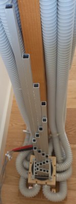
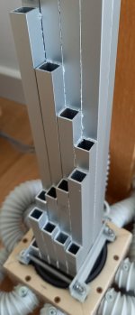
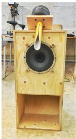
In the MDD3H240 prototype the front acoustic load (MDDFL) is made with 25 aluminum waveguides of increasing length, from 22 to 618 mm, like a virtual array of tweeters. The wave front emitted by the speaker cone is partly sent into the listening room and partly divided between the 25 waveguides. At the end of the waveguide, a spherical wave front is generated which makes the emission omnidirectional at all frequencies.
The drive is located close to the floor and therefore does not generate reflections with it.
Increasing lengths generate delays of between 0.1 and 2 milliseconds. The delay interval of the secondary sound fronts is further dilated by the omnidirectional emission, the number of paths of different lengths in which the sound energy propagates is increased. The possibility of perceiving the precedence effect studied by Haas is reduced. The same sound continues to arrive with increasing delays and not as distinct events that would tire the listening.
Thanks for your attention, I am available to anyone who would like more information.
Claudio Gandolfi - MDD (Multi Delays Diffraction Loudspeaker)
MDD3A89
https://www.diyaudio.com/forums/pla...idirectional-single-drive-17.html#post6599019
- a frontal one (MDDFL) to make the high frequency emission omnidirectional, I think it can be used in multi-way systems,
- a rear one (MDDBL) for medium-low frequencies.
At the moment I don't need to build a multi-way system. I want to report my prototype for an opinion on the use of the MDDFL front loading with midrange and tweeter.
In the MDD3H240 prototype the front acoustic load (MDDFL) is made with 25 aluminum waveguides of increasing length, from 22 to 618 mm, like a virtual array of tweeters. The wave front emitted by the speaker cone is partly sent into the listening room and partly divided between the 25 waveguides. At the end of the waveguide, a spherical wave front is generated which makes the emission omnidirectional at all frequencies.
The drive is located close to the floor and therefore does not generate reflections with it.
Increasing lengths generate delays of between 0.1 and 2 milliseconds. The delay interval of the secondary sound fronts is further dilated by the omnidirectional emission, the number of paths of different lengths in which the sound energy propagates is increased. The possibility of perceiving the precedence effect studied by Haas is reduced. The same sound continues to arrive with increasing delays and not as distinct events that would tire the listening.
Thanks for your attention, I am available to anyone who would like more information.
Claudio Gandolfi - MDD (Multi Delays Diffraction Loudspeaker)
MDD3A89
https://www.diyaudio.com/forums/pla...idirectional-single-drive-17.html#post6599019
Attachments
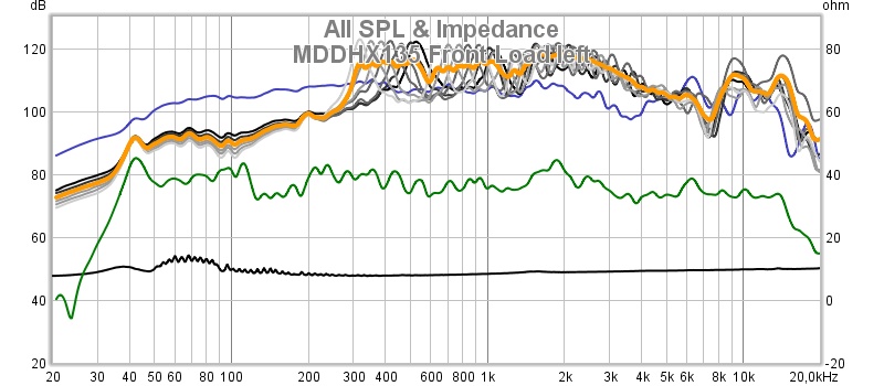
How do you account for what is very likely "peaky" (high Q) resonances in the vertical pipes? These could really prevent your frequency response from being flat. At least that is what I am seeing in this frequency response plot start at 300Hz and up - a ton of pipe resonances! Your vertical axis scale is 20dB per division!
I too would like to see some kind of measurements in the far field, but that might be difficult to do properly indoors.
In my opinion the way you measure the responses (image copied from one of your pages) with the microphone inside a "pipe" is not correct because the microphone is almost as wide as the pipe and will therefore alter the resonant response and partially block the output.
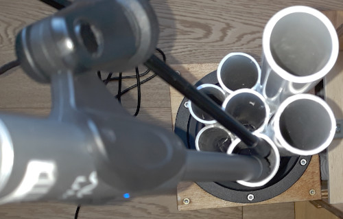
The mic could be placed at a right angle to the pipe opening next to and just outside of the mouth.
If you are a builder/tinkerer type, you can build whatever and if it sounds good to you then you are done. But I would really like to know more about why you are constructing the speaker in this way, and why you think this "works". Are you trying to distribute the output of the single fullrange driver over a larger area?
I too would like to see some kind of measurements in the far field, but that might be difficult to do properly indoors.
In my opinion the way you measure the responses (image copied from one of your pages) with the microphone inside a "pipe" is not correct because the microphone is almost as wide as the pipe and will therefore alter the resonant response and partially block the output.
The mic could be placed at a right angle to the pipe opening next to and just outside of the mouth.
If you are a builder/tinkerer type, you can build whatever and if it sounds good to you then you are done. But I would really like to know more about why you are constructing the speaker in this way, and why you think this "works". Are you trying to distribute the output of the single fullrange driver over a larger area?
Last edited:
I am wondering if you are familiar with the effect of pipe resonances in the time domain?
Resonances store energy. So when the air inside the pipe is stimulated by the speaker, and then the speaker stops playing, the resonance does not stop. This is especially the case when the Q is high, like with your long narrow pipes. The stored energy takes a bit of time to dissipate. So the music energy coming out of the speaker at any instant will be taken up into the resonance and then the "note" will continue to occur without further stimulus. In short, your music will be "smeared" out in time at all the frequencies where the resonances are occurring. This is not typically considered to be something that is desirable in a loudspeaker.
Have you considered this aspect (the time domain behavior) of your multi-pipe design?
Time and frequency domain
Hi CharlieLaub
thanks for your comments, allow me to give more information on MDD prototypes.
You are right when you criticize my measurement methods, they are not professional. I made them this way because I wanted a qualitative idea of what happens in the system, my prototypes are not intended for production and sale. The configuration is definitely unconventional and there is no mathematical model that allows me to describe it. However, the measurements helped me to improve the quality of the reproduction in subsequent steps. Writing posts on the DiyAudio forum also helps me better understand how MDD prototypes work, and participating in the forum has another advantage, I am forced to practice English, I almost totally depend on Google Translator.
I have no experience of listening with hi-end audio systems and I don't know if the level reached by the MDD prototypes can satisfy other DIYs. The most expensive speakers I have bought are JB3 in 2009, I stopped using them in 2013. I am a computer teacher but I can understand how audio technologies work. I decided to make inexpensive speakers for multimedia projects.
The irregular frequency response is mainly caused by the geometry of the listening room. I tried a couple of times to swap the left and right speakers, the peaks in the two channels remained in the starting position. By now I recognize the responses of the two channels from some characteristic forms that are replicated in the various prototypes.
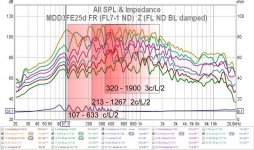
The peaks related to the internal resonances can be seen even better in the measurements made on the prototype MDD3FE25d, they correspond to the frequencies between c / (Lmax * 2) and c / (Lmin * 2). The front acoustic loading has waveguides open on both sides, environment and compression chamber. This solves the problem of supposed tails caused by the damping of the energy accumulated in the air inside the waveguides. Both sides of the waveguides are in acoustic short circuit, they discharge at the speed of sound in a few milliseconds.
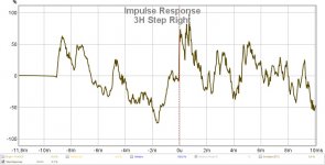
The graphs show the answers to the step of the MDD3H240 prototype. In the left channel, the reflections of the posterior and lateral walls are clearly visible. In the right channel, only the reflection of the posterior wall is visible. Subsequently, the trend becomes complicated, I can assure you that the sound is not dirty.
One last consideration, I am unable to take the test due to a lack of materials and skills in multi-way systems. The MDDFL acoustic load can be used to make a ribbon tweeter omnidirectional. It is mounted facing upwards, placing a suitable number of waveguides in sufficiently rigid material above it, by adjusting the lengths you will obtain an omnidirectional emission around a vertical axis.
On the home page the summary of my prototypes.
In the MDDBL tread some considerations also applicable in multi-way systems
claudio
Hi CharlieLaub
thanks for your comments, allow me to give more information on MDD prototypes.
You are right when you criticize my measurement methods, they are not professional. I made them this way because I wanted a qualitative idea of what happens in the system, my prototypes are not intended for production and sale. The configuration is definitely unconventional and there is no mathematical model that allows me to describe it. However, the measurements helped me to improve the quality of the reproduction in subsequent steps. Writing posts on the DiyAudio forum also helps me better understand how MDD prototypes work, and participating in the forum has another advantage, I am forced to practice English, I almost totally depend on Google Translator.
I have no experience of listening with hi-end audio systems and I don't know if the level reached by the MDD prototypes can satisfy other DIYs. The most expensive speakers I have bought are JB3 in 2009, I stopped using them in 2013. I am a computer teacher but I can understand how audio technologies work. I decided to make inexpensive speakers for multimedia projects.
The irregular frequency response is mainly caused by the geometry of the listening room. I tried a couple of times to swap the left and right speakers, the peaks in the two channels remained in the starting position. By now I recognize the responses of the two channels from some characteristic forms that are replicated in the various prototypes.
The peaks related to the internal resonances can be seen even better in the measurements made on the prototype MDD3FE25d, they correspond to the frequencies between c / (Lmax * 2) and c / (Lmin * 2). The front acoustic loading has waveguides open on both sides, environment and compression chamber. This solves the problem of supposed tails caused by the damping of the energy accumulated in the air inside the waveguides. Both sides of the waveguides are in acoustic short circuit, they discharge at the speed of sound in a few milliseconds.
The graphs show the answers to the step of the MDD3H240 prototype. In the left channel, the reflections of the posterior and lateral walls are clearly visible. In the right channel, only the reflection of the posterior wall is visible. Subsequently, the trend becomes complicated, I can assure you that the sound is not dirty.
One last consideration, I am unable to take the test due to a lack of materials and skills in multi-way systems. The MDDFL acoustic load can be used to make a ribbon tweeter omnidirectional. It is mounted facing upwards, placing a suitable number of waveguides in sufficiently rigid material above it, by adjusting the lengths you will obtain an omnidirectional emission around a vertical axis.
On the home page the summary of my prototypes.
In the MDDBL tread some considerations also applicable in multi-way systems
claudio
Attachments

Attachments
Hi AllenB
The K-Tube system uses diffraction to modify the spatial distribution of acoustic energy at high frequencies, control is obtained with an appropriate exponential profile. The MDD system is very similar in the first section of the K-Tube waveguide. In the K-Tube, the emission of energy by diffraction interacts with the sound front that runs through the wave guide, modifying it. With MDD technology, the wave front is split at the input of the waveguides and the individual emissions by diffraction do not perturb the wave fronts that run along the side by side waveguides.
With MDD technology it is possible to distribute the sound energy on a vertical line of much greater length than the K-Tube, with even greater horizontal dispersion.
The main disadvantage for MDD technology is the lack of a mathematical model validated by a sufficient number of realizations.
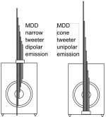
In the drawing two possible mounting schemes of a tweeter with MDD acoustic load.
claudio
The K-Tube system uses diffraction to modify the spatial distribution of acoustic energy at high frequencies, control is obtained with an appropriate exponential profile. The MDD system is very similar in the first section of the K-Tube waveguide. In the K-Tube, the emission of energy by diffraction interacts with the sound front that runs through the wave guide, modifying it. With MDD technology, the wave front is split at the input of the waveguides and the individual emissions by diffraction do not perturb the wave fronts that run along the side by side waveguides.
With MDD technology it is possible to distribute the sound energy on a vertical line of much greater length than the K-Tube, with even greater horizontal dispersion.
The main disadvantage for MDD technology is the lack of a mathematical model validated by a sufficient number of realizations.
In the drawing two possible mounting schemes of a tweeter with MDD acoustic load.
claudio
Attachments
- Status
- This old topic is closed. If you want to reopen this topic, contact a moderator using the "Report Post" button.
- Home
- Loudspeakers
- Multi-Way
- MDDFL: floorstanding, virtual array, omnidirectional mid-tweeter acoustic load