Tubelab SE build and power supply questions.

Ok, well I'm well on my way getting this thing built. I figured that I'd post my questions here as I know George is a busy guy, and I'd like to get others input as well. I have done a search for these topics, but haven't found answers to my particular questions.

I have constructed the board with all components on the bottom so I can mount the board to a chassis with only the tubes coming through the surface. The only problem is mounting the semiconductors. Not really sure the best way of approaching this. Is it ok to mount the front side to the heat sink to keep the orientation of the heat sinks the same or would this not work? Do the heat sinks have to be attached to the board? I see no traces going to or from the board connections for them.

Secondly, I will be using 300B's with this board and am shooting for a B+ of as close to 400V as I possibly can get. George states at his site that C4 and R4 are responsible for setting the B+, the higher the value of C4 and the lower the value of R4 will raise the B+. For the power transformer I'll be using either the 273 or 373CZ with a 5AR4. I might use a choke and replace R4, but only if hum becomes an issue.

Finally, I'll need to have balanced inputs for the amp to interface with my balanced studio gear. I will use some kind of Edcor transformer. Not sure what secondary impedance to use, but my studio gear runs at 600 ohms. Will there need to be any modifications to the existing circuitry to interface with a transformer? Also I could not find in the assembly manual anywhere how to connect the inputs. There are 10 pads at the front of the board where the inputs/volume control go, but not sure how to wire them. Also I will not be using a volume pot, will I need to solder a resistor in it's place or just a jumper?

Looking forward to your responses. I'm going to play in the snow YAY!

Thanks,
Joe

  • Locked
Infinite baffle woofers in an enclosure

I’m planning to build a pair of large floor-standing speakers which will contain a pair of 12” woofers, a 6” midrange and a 1” tweeter.

I found an interesting woofer which, in fact, may be a subwoofer. At least, the price is affordable and the appearance is right to my eyes. It’s GRS 12PR-8. GRS 12PR-8 - 12" Woofer

I went to an online calculator and put the driver’s parameters in it. Yet, I was astonished when the results obtained was suggested that these woofers need about 925 litres of sealed enclosure volume, also produce Q about >= 1, recommended Q was approx. 1.6!

Thus, I’m wondering that if these woofers are designed for infinite baffle. However, as my intention is to build sealed enclosures which will have volume approximately 85 litres (3 cu.ft.) per woofer and crossing them at about 85 Hz with 12 dB/octave slope.

I doubt that if these woofers are really designed for infinite baffle enclosure type, can I put them into a sealed enclosure? Will it have any problems? Is it a bad idea?

Edge Electronics M4 question

Hello, I recently blew a fuse in one of my much preferred power amps. Taking it apart to replace I see (I am well out my scope of knowledge here, so my apologies in advance as I bounce off of obvious answers) it has unlike many other power amps only two main power caps. A matching pair of screw top 18,000uf Mepco/Electra 75 VDC.

Amp is approx 20yrs old. Inquiring about the possible advantage of replacing these with newer and possible upgraded caps. Not looking to spend money just to spend it, but if after 20yrs these caps have served their time well but are tired or other ($100 budget) replacements might present a marketable upgrade to the sound.

Thank you in advance and please excuse the lack of nuanced/educated questions.

Attachments

  • edge1.jpg
    edge1.jpg
    984.9 KB · Views: 119
  • edge.jpg
    edge.jpg
    712.6 KB · Views: 105

Mini subwoofer

Hi

I'm planning to build a small tabletop speaker, or a set of two to get stereo. This is my first build and I have some questions about bass. It seems I have some options when it comes to handling the thinks going on on the backside of the sub driver.

  1. I could box it in and dampen the walls. In an ideal dampening I'd get some attenuation of the membrane, but nothing that would show up as a peak or dip in the frequency response. Just a weaker signal over the whole spectrum.
  2. I can do some kind of wave guide to channel the energy, or waves, on the backside of the membrane out of the box. The wave guide must be dampened or else there will most likely reflections, which will show up on the response.
  3. Another alternative is to have a smooth wave guide that have a resonant frequency, kind of like a horn instrument. However, the wave guide must be quite long to affect the lower frequencies, 1.5 to 2 meters long. 1.7 meters if the resonant frequency is 50 Hz and the speed of sound is 340 m/s.

Okay, does anyone have any word of advise before I start designing a mini woofer? Is there any relevance of my assumptions above in the real world?

STAHL - 'Acebass' Synthesis of Loudspeaker Mechanical Parameters by Electrical Means

: A new Method for Controlling Low-Frequency Loudspeaker Behaviour

$ 20 for non AES members.
Worth buying? Does it present a practical evaluation circuit?

I can see the merit for high Qes drivers forced electronicalyl to be low Qes,but is there some disadvantage apart from complexity?

Ive seen the experimental schematic as available in HIGH PERFORMANCE LOUDSPEAKERS edited by MARTIN COLLOMS.

Seems interesting to adjust amplifier output impedence to negate Loudspeaker Re,but then also adjust CMS etc(directly or indirectly?)

Im interested in both servo and this issue wrt transient response and resonance of bass units.

http://www.aes.org/publications/preprints/preprints_search.cfm

Mike.e

ACE-Bass is a really effective alternative to MFB.

http://www.diyaudio.com/forums/showthread.php?postid=360363#post360363

I've built a few sub boxes over the past 10 years using ACE-Bass, from twin 6.5" to quad 10", with 3db points as low as 20Hz.

The degree of control the electronics has over the cone is quite staggering. If you try to manipulate the cone with the system on, it actually feels heavier, stiffer, more damped, with a lower Fs (assuming you choose to increase all of these terms).

You just have to listen to one of those little Yamaha subs to realise that for such a small driver, being driven hard in a small box, the LF extension is quite impressive. Applying the technology to less compromised drivers running a much larger headroom results in very impressive performance, especially if dual subs are arranged in push-pull fomat.

If you look at Stahl's original AES paper on the technology, he prints some fine examples of measured improvement in performance and range extension, comparable to the best commercial MFB systems.

No messing around with accellerometers, and the system works great with a vented box, giving plenty of efficiency down low (if you choose that avenue).

For the DIYer, I think it would be much harder to get better performance from a MFB system compared to an ACE-Bass system design with the same effort.

http://www.1388.com/articles/tech_Ace-Bass/
Synthesis of Loudspeaker Mechanical Parameters by Electrical Means: A new Method for Controlling Low-Frequency Loudspeaker Behaviour
A method for extending bass response and lowering distortion in louspeaker systems, which differs from both equalized and servo or feedback systems, is described. It can be seen as an extension of the technique to increase loudspeaker damping by giving the driving amplifier a negative output resistance. However, this method also controls the moving mass and compliance. Very good results, such as flat frequency response down to 20 Hz and excellent distortion data, have been achieved with moderately sized bass-reflex enclosures.
Preprint Number: 1381 Convention: 61 (October 1978)
Author: Stahl, Karl Erik
E-lib Location: (CD aes9) /pp7680/pp7811/1483.pdf
downloadable electronic version PDF (642 KB) $5.00 AES Member | $20.00 Non-Member
hard copy $5.00 AES Member | $20.00 Non-Member

Red led flashing on my Cyrus 8vs - PSU Checker fault?

Hi to everyone,

the standby light of my Cyrus 8vs is flashing red, and the amp does not power up.

I've checked all the expected voltages, and everything is ok.

In the "PSU Checker" area (apparently based on IC402, an LM393) I've noticed that the R408 SMD resistor seems to be open. Moreover, that resistor is completely white, with none readable marking on it.

Here attached a picture of the area involved.

Anyone could help me to retrieve the 8vs schematics, or at least the proper value of R408?

Thx a lot in advance to everyone

Attachments

  • R408.jpg
    R408.jpg
    600.1 KB · Views: 300

tutorial

Hi I'm new to the site so hi to all I have a audio innovations alto mk1 in black there are plenty of discussions to read about this amp but i cant find anything regarding strip down procedure as I'm going to recap it shortly, has anyone got a tutorial for me or if you have done this can you provide me with a description of how you went about it if at all possible, thanks

Best 8" speaker drivers to install in old cabinet

Hi there,
I'm new to the speaker scene and wanted some opinions on what I should do.

Recently took a set of Advent Heritage speakers to be re-foamed (only the two full-range drivers the tweeters are fine). After hearing back from the technician I discovered that they'll need to be re-coiled as well. The repair cost is going to be so high I deemed it not worth the expenditure.

So my question is what 8" drivers can I install in the cabinets without changing any of the crossovers. As I mentioned earlier I'm a bit of a noob when it comes to this, so any advice would be much apricated. And obviously, I'd like the drivers to be the best possible quality without breaking the bank (around $70 per driver is my budget).

Thanks again🙂

USB Soundcard Problems

Hi Guys,

I'm hoping that someone can help.


Currently I am using a soundcard at work for noise monitoring and recording.

I am having a problem getting the soundcard to be recognised by the Windows 10 system.

We have several sets of equipment, OSC2,3,4 &5.
OSC5 works perfectly.
OSC2,3,4 give high readings.

So we tried troubleshooting by swapping the soundcards around.
Cannot get it to work!

Using the OSC5 system, the cards from the other systems are not correctly recognised.
Inserting the usb into the computer, a dialog box appears giving the correct info. about the box.
The computer gives the bingbong as it is inserted.
However, almost immediately it gives the second bingbong and then a third bingbong.
like the plug had been pulled and then reinserted.

No data is received from the soundcard.

Anyone any ideas??


Andu

Attachments

  • soundcard.jpg
    soundcard.jpg
    349.8 KB · Views: 157

Trustworthy Matched LSJ74 Source - MAY 2021

Greetings fellow earthlings,

I'm looking to build the Aleph J clone and it seems like everything will be pretty easy to get, except for the "new" Linear Systems JFETs.

Are there any known trustworthy sources for these matched JFETs at this time? I would much prefer to order from DIYAudio, but they only have them available in the quad kits paired with the LSK170.

I am tempted to buy two of these 74/170 kits to get them, but I'd rather leave that stock available for folks that need that configuration.

Cheers,

--JBaeckel

Miniature electrolytic capacitors shootout - Best for Coupling to Headphones?

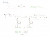
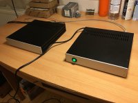
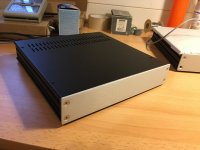
Last year, after building up my second XRK971 Pocket Class A amplifier board, I did some extensive output cap rolling in a quest to find the best-sounding electrolytic caps for coupling the amp to my 50 ohm headphones. I was surprised at just how different the various caps sound in the signal path.

Some of this was posted in the Pocket Class A forum and some on Head-Fi. Now I'm rounding it all up in one place with the hope that it might be useful to somebody. No, these weren't blind tests. You don't have to believe my ears. Try testing for yourself and see if you agree!

9979922.jpg


The majority of my listening tests were performed through ATH-M50 headphones, which I have found to be invaluable for giving an honest rendering of sonic differences. These findings were confirmed through further comparisons using my Sennheiser HD598. I also auditioned the caps while using the Pocket Class A as a preamplifier to feed two different Class D-powered nearfield speaker systems. Sources were a wide variety of FLAC files played both from my XDuoo X3 DAP and my ECHO Audiofire soundcard.

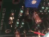
This test was intended to compare caps of similar physical size that would fit into the available space on my PCB for this particular build. This turned out to be 10x20mm, though a few (marked with asterisks) were 12.5x20mm, and then the OSCONS are smaller than all the rest. I believe that controlling for size vs. specs likely reduces the accuracy of some of my comparisons somewhat, since voltage and capacitance ratings varied between caps tested.

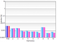
Voltage rating varied from 16V to 25V. Theoretically a cap rated for higher voltage exhibits less distortion, per Cyril Bateman. I tested some types at multiple ratings and found that in reality, this effect was difficult to hear. Different capacitor brands and series had much more audible effect than different voltage ratings.

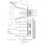
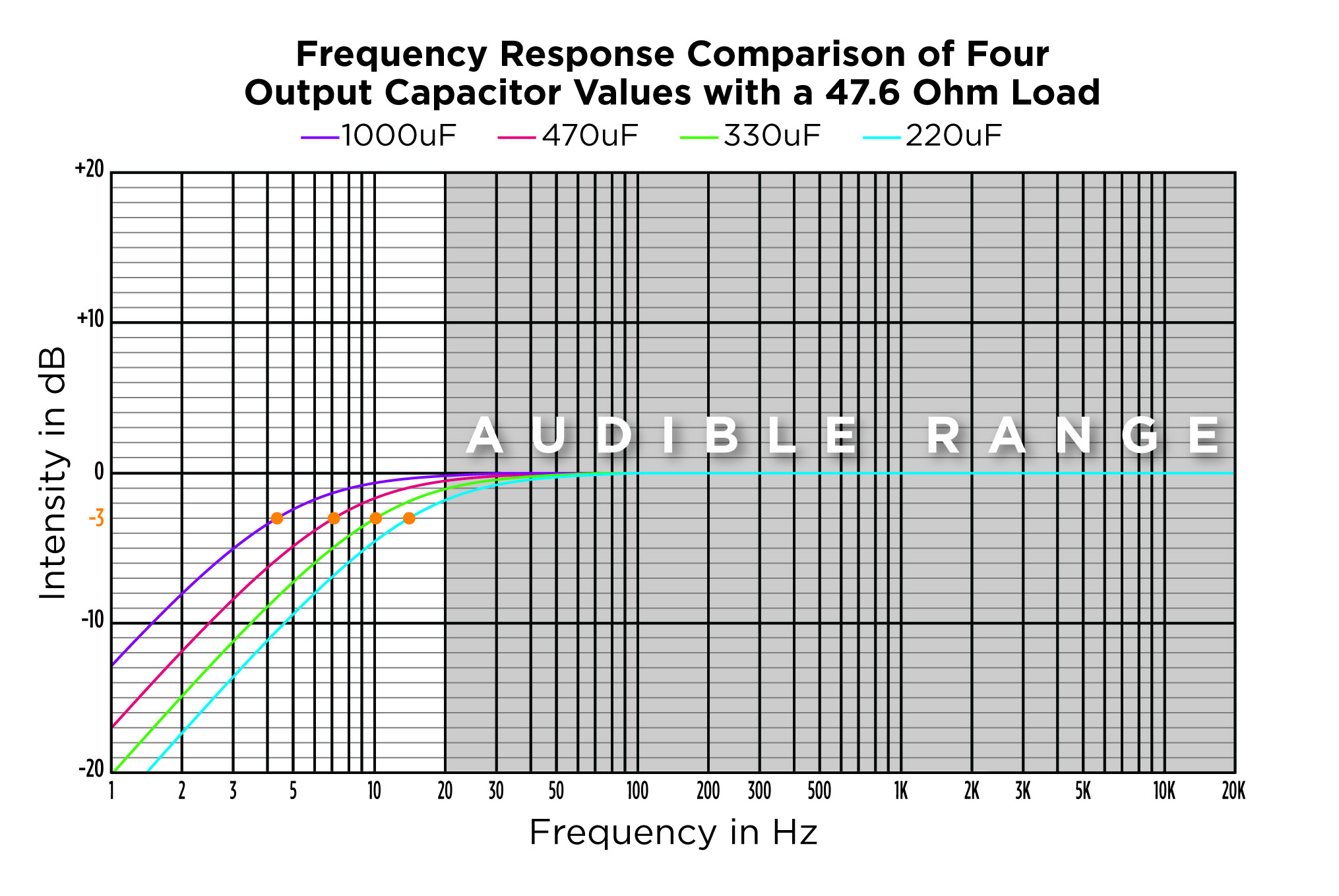
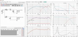
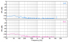
Capacitance varied from 220uF to 1000uF. Of course, this affects the low corner frequency. All of these caps provided satisfying bass quantity...in truth even a -3dB rolloff at 15Hz is only noticeable with critical listening comparisons. This chart shows predicted bass response of each cap value with my headphones...both pairs are 50 Ohms, and in parallel with the amp's 1K load resistor, the total load is 47.6R.

9974838.jpg


Here are my listening impressions:

Nichicon KW
value tested: 25V 1000uF
Reasonably pleasant, but the treble is quite dulled. Nicely engaging, slightly grainy mids. Bass extends low but is a little uncontrolled and surprisingly quiet for a 1000uF cap. Subpar detail and dynamics.

Nicicon FW
value tested: 25V 1000uF
Brighter than KW. More balanced mids sit on par with the rest of the spectrum. Clearer treble, with some sparkle, but still lacking air up top--stuffy. Good presence in mids, with just the right amount of bite. Bass quantity is better than KW but a bit distorted.

Nichicon Fine Gold FG
values tested:16V 470uF and 25V 330uF
A small step closer to KZ sound in resolution and overall engagement. Smoother than KW or FW, with a balanced frequency response. Deep, punchy and controlled bass. Still a bit "closed in" due to being a bit short on high treble. These can sound strained in louder passages. The 25V may be a hair smoother, with a little more treble, but not enough to avoid a similarly small, stuffy soundstage. Where is the high treble, Nichicon? In the KZ only, I guess. Sheesh.

Nichicon KA
values tested: 25V 470uF and 25V 1000uF
The KA actually stands out from the typical Nichicon "house sound" IMO. It has a slightly mid-centric signature with enough treble to sparkle some, though the treble is a tad hot. Midrange and vocals come forward in the mix nicely, but without grain--they are the smoother than even the FG. Bass has decent weight and control. Somehow I find the KA more natural in timbre than all the other Nichicons. The sound is clearer, though not particularly airy or exciting.

Panasonic FR
value tested: 25V 1000uF and 25V 1500uF*
FAR more neutral and revealing than all of these Nichicons. Maybe its the ultra low ESR…it just gets out of the way and lets the music come through. It gives the cleanest and most spacious presentation, with excellent detail and real air on top for a beautifully open soundstage. The bass is awesomely powerful with deeper extension than any of the Nichicons, and tight control. Blackest background. Fastest transients. Need I say more? If I had to nitpick, I'd wish for a touch more warmth and presence in the mids, but I suppose that might just be a coloration that suits my taste. These caps simply sound REALISTIC.

Panasonic OSCON
values tested: 25V 390uF and 16V 1000uF
I found these to be extremely well balanced thorough the frequency range, with excellent bass weight and particularly great bass control. The bass is just effortless. Overall these have a full, warm and creamy sound signature. But it has a soft/dull one-dimensionality to my ears, and fails to engage me. These fall short on detail compared to all other caps I have tried.

Elna Cerafine
values tested: 16V 330uF, 25V 220uF, 25V 470uF*
I can see why a few people like these more than Silmics. They have more midrange forwardness and bite to them, and at first blush seem to offer a more engaging sound. However, their treble can be a little harsh after a while, and the response is rather poorly extended on both extremes of the frequency spectrum, resulting in a less detailed, somewhat boomy and congested sound, with noticeably less bass control than the Silmic. Not my cup of tea.

Elna Silmic II
value tested: 16V 220uF
Bass has flawless texture, speed, and extension, even with a marginally undersized 220uF cap. A polite, soft midrange and treble makes you want to crank the volume, and the overall sound is nice and full. It hides the flaws of harsh recordings, but also seems to push vocals farther away and hide some harmonic texture, resulting in an odd hollowness in midrange timbre. I'd say these sound spacious due to decent extension and a somewhat exaggerated treble sparkle, but the high treble is missing. I particularly dislike the way these do metal percussion. Cymbals and hi-hats do not sound realistically metallic. Other than that, these sound great, if slightly veiled in parts of the spectrum.

Nichicon Muse KZ
value tested: 25V 330uF*
Nice. These are quite detailed, with a beautiful, jangly midrange and sparkly treble that gives an incisive "electric" sound to the upper ranges. Vocals really jump out and grab my attention so that song lyrics have excellent intelligibility. The overall presentation is ever so slightly on the hot/forward side of neutral, with a hint of upper mid harshness, but the overall timbre is natural, with enough treble to give an open soundstage. Metal strings and percussion sound right. This size gives impactful, fast, and detailed bass with my 50R cans. With these, I never feel like I'm missing any detail whatsoever, and I wouldn't say the soundstage is huge, but certainly bigger than either Elna. They're lightning fast, and darn revealing.

------------------

Conclusion
After all this, I now believe that NO electrolytic cap on the face of the planet is totally transparent in the signal path. My favorite in this application turned out to be the Panasonic FR, and I believe these to be the most transparent of the bunch, although I can absolutely understand how others might prefer the other "flavors"--particularly the KZ and Silmic, which each have their strong points and are justifiably loved by many.

Conspicuously missing from this lineup is the Nichicon Muse Bipolar BP and the Panasonic FC. I have heard good reports about both and hope to test them eventually.

Speaker mounting hardware

As a relative newbie to DiY speakers i would like to know what is the preferred way to mount speakers in a wood cabinet. There is ,of course, wood screws and versions of sheet metal screws. These fasteners tend to lose there grip if they are played in and out a few times.
I wonder if it is common to use machine screw treaded anchors mounted and maybe glued into the cabinet and then mount the speaker with a hex head machine screw. Would this method be less prone the loosening up with repeated mounting? Just look for some advise. Thanks
hlf

Working the front-plate myself

Hi!
Aluminium is rather straight-forward and easy to work, but patience/focus is required to get good results.

I don't want to spend a lot (yet) for finishing my chassis (that is, save the money). I want the front-plates with knobs and everything rotating recessed, and some lettering on it...

It is ok not to get the very same results as an order at modushop would yield, and I'm fine with tedious manual work, or working with handheld carpenter-machines. is it feasible?

Are specialized tools needed?
How could I get some text/icons on it, having it looking quite good and "resilient"?

I'm hoping somebody could tell me a easy/money-saving method?

Thank you for tips!

"injecting" audio into an AVR

Am wondering if it would be possible to inject line level audio from a pre-amp into an AVR.
It's a Harman Kardon avr7300

Am thinking I could tap into the blue circle area and "cut" the red line(s)
I see the avr7300's pre-outs tap into the same feed, so thinking that their output levels would indicate what the amp is expecting.

The manual doesn't state the pre-out specs 🙁

Q7iRQw7.jpg

help me improve on this current design

hi guys ,
i made this amp from a schematic a frnd shared , although i am content with this amp i dont get the crystal clear and airy highs i have felt with other amps also when i tested with square wave everything becomes fugly after 5khz , i have even reduced the miller cap but still the ultra clear highs are not present , does this amp needs a EF3 as my speakers do dip to 2.5 ohms at some frequencies ...


regards
phoenix

Attachments

  • xyz (1).jpg
    xyz (1).jpg
    161.8 KB · Views: 331

Accuphase P300X Relays

I will get a Accuphase P300X for rapair. The main relay is not working any more. Therefore we want to replace the relays.

Main Relay: Omron MY4-02-US-40L DC 48V
Replacement found on Digikey:
Blocked
Speaker Relay: Omron LY2S-US DC 24
Digikey link
Blocked

Digikey was trying to help us, but the don't know what -US- means.

here a nice link:
accuphase p-300x

many thanks
Dieter

FS Pass ACA Amp 1.6 Black

Hello,

I am selling a Pass ACA Amp v1.6 with black case; can be used as a monoblock through the XLR output. Solders were made by a professional a year and a half ago. I am selling it because I changed my speakers and I am not using it anymore.

Asking 350€ + shipping. See photos below, I can send more on request.

Attachments

  • photo_2021-01-12_21-01-08.jpg
    photo_2021-01-12_21-01-08.jpg
    70.2 KB · Views: 872
  • photo_2021-01-12_21-01-08 (2).jpg
    photo_2021-01-12_21-01-08 (2).jpg
    84.8 KB · Views: 883
  • photo_2021-01-12_21-01-09.jpg
    photo_2021-01-12_21-01-09.jpg
    98.7 KB · Views: 870
  • photo_2021-01-12_21-01-11.jpg
    photo_2021-01-12_21-01-11.jpg
    112.3 KB · Views: 877
  • photo_2021-01-12_21-01-10 (2).jpg
    photo_2021-01-12_21-01-10 (2).jpg
    99.2 KB · Views: 868
  • photo_2021-01-12_21-01-10.jpg
    photo_2021-01-12_21-01-10.jpg
    98.3 KB · Views: 351

Small 3 liters desktop monitors "Monithor"

Proud to introduce you my last project, "Monithor"
3 liters small 2-way desktop speaker using Ciare and Peerless drivers:
Ciare MT200 tweeter
Peerless SLS85 mid-bass

Attachments

  • 165102002_10225228836457955_3211439836831970547_n.jpg
    165102002_10225228836457955_3211439836831970547_n.jpg
    189.1 KB · Views: 357
  • 165493010_10225228841578083_6308463265341156554_n.jpg
    165493010_10225228841578083_6308463265341156554_n.jpg
    366.9 KB · Views: 347
  • 165302538_10225228835257925_7909672484287831877_n.jpg
    165302538_10225228835257925_7909672484287831877_n.jpg
    27 KB · Views: 359
  • 167510602_10225272136700434_7240665981017325938_n.jpg
    167510602_10225272136700434_7240665981017325938_n.jpg
    59.8 KB · Views: 346

Gladen XL

Gladen XL no Bias

Hi there,

years ago i bought a broken Gladen amp. I tooked it to a guy, i thought he know what he does. It came back with horrible solderpoints and its not working.

Rails +- 45V, at the TLs at pre-amp i have +- 9V.

Output transistors get no bias. Across drive-transistors (AH-16/BH-16) B->E 0,5V.

I stuck a bit. Any schematics or something? Audio Systems 280.2 and 300.2 are very similar to this.

Thanks

Grounding Issue or Something Else?

Hi all,


I've been working on designing/building an op-amp based headphone amplifier. The power stage is driven by the LT3080/LT3015 linear regulators, and the output stage is driven by the LM4562 (for gain) and LT1206 (for current) op-amps.


The ground scheme is as follows: all of the grounds related to the power section are tied to a small "power GND" bus, and all the grounds related to the signal section are tied to a small "signal GND" bus. There is 1 jumper that runs between these two ground buses to tie them together.


I've built a prototype of the system on perfboard, and the audio itself sounds quite good. However there are a few issues with noise that I'm facing:


  1. Occasionally I can hear short bursts of clicking sounds through the headphones. I find that this effect is more frequent when I plug into the power outlet that my computer/modem runs on. Strangely, I also find that if I hold the amp further away from the wall then this almost completely stops, which makes me think it's some kind of EMI issue (though it could also be an issue with my AC/DC converter cabling).
  2. If I run the amp with my phone as the source, I can sometimes hear radio signals being picked up. I currently don't have a metal enclosure, but I'm thinking adding one and grounding the chassis could fix this?
  3. With certain 3.5mm cables driven from my computer, I find that I can get different amounts of buzzing on my output. The shortest cable I have buzzes quite a bit, while my longer cables don't buzz at all.
I was wondering if anyone has any insight into what my issue might be? Especially concerning observation 1, I'm pretty lost on what to try next. I've tried increasing the size of my decoupling capacitors before the regulators, which (subjectively) seems to have helped a bit, but the clicking remains. Most of the noise in the system doesn't seem to vary much when I increase the volume of my source signal. Photos of the board are here: Imgur: The magic of the Internet


Any help would be greatly appreciated!

Thanks

Advice on my DIY build.

Hi, Newbie on this forum and the DIY scene.


I am hoping for some advice. I am a stickler on recycling stuff in my house.

I have a coffee table shaped like a cabinate 720x220x400mm (63liters). a pair of EMU-XM7 (2way -5") (i know i am committing a sin) and a 6.5" Yamaha midbass woofer, powered by an Arylic 2.1 amp.


I want to put all these into the exclosure and know i will be sacrificing stereo.

I have tried to use the cabinate calculator but it has totally confused me and wonder if anyone here can advise me.


1) Is the enclosure too big?
2) Do i need a vent?
3) Should i enclose the 5" and the tweeter?
4) Should i build a seperate enclosure for the 6.5" ? and vent ?


I plan to use the cross-over from the EMU-XM7 for the 5" and tweeter.. and use the subwoofer function from the arylic2.1 to drive the 6.5".


Any feedback will be appreciated! thanks again guys. This is a place full of information though confusing for a newb. 🙂


Here is the ideas of the layout.

Screenshot 2021-05-12 013213.jpg - Google Drive

An externally hosted image should be here but it was not working when we last tested it.

Golden Tube Audio SE-100

Hey all, While I am finaly getting underway on the Quicksilver 8417 Clone amp I am building (only took me two years to plan) I saw a Golden Tube Audio SE-100 for sale locally, so I bought it (don't tell the wife).

This amp was laying around for years and had a layer of dust and crud all over it. I lugged it al the way home (all 80 pounds of it) and cleaned it off. Blew out the amp chassis with compressed air and wiped it down. I then wiped off the EL34 tubes (10 in all, one drivers and the other four are paralleled - per channel). I tested them on my tube tester and they were all in the high 90%. They are Electro Harmonix.

The input tube was a 6SL7 I think (no markings). and tube tester said it was fine too.


Anyway brought it up on the variac and zeroed the bias pots. One tube started red plating, and was reading over 1.9v (supposed to be biased to 450mv). Yikes!...Shut it down and worked the bias pots back and forth for a few minutes - did the same to all the other pots. Started back up and all was ok...bias up to 350mv for 5 min, then 400mv for another 5 min, then on to 450mv (actually says to bias to 500mv, but I will leave it at 450mv)

Anyway, put it on a pair of B&W DM 220 (my beaters) and sounded good, but had a bad hum that was clearly audible with cd paused. Also had a ton of gain.

I found the schematic (attached - don't know if correct) and it listed the input tube as a 6SN7, so I swapped it and gain lower and hum went down considerably... still need to do some critical listening...not a bad sounding amp. I like.

Anyway a couple questions.

This amp is listed as 100 watts, class AB Push Pull - Huh? Its Single ended paralleled, like its little brother the SE-40. ..and aren't all Single Ended parallel amps class A?

Also, what is the "correct" tube for input - 6SL7 or 6SN7? Quite happy with the 6SN7 in that spot...

Pics later...

Attachments

FEP/FEN/FED16xx rectifier failures constantly

I don't really know why but I find them failed or they fail in front of me all the time. The single and doublers just the same. Seems like just about every single amp that comes in with these type/brand/number on the rectifier will need to be replaced. The MUR1620CTG/CTRG have been holding up well, but the dual doublers are only available in FED16/CT/BT/DT/FT part suffixes from what I've searched.

I mean, I've even had them pop after an amp repair, when what I repaired had nothing to do with the power supply nor outputs, nor rectifiers. Like, after cleaning a switch/gain control.

Are these parts just very poor quality? I'm always finding them shorted to begin with, or they short under non-severe load testing.

Its not just Soundstream amplifiers either. I've found these in a bunch of old Orion amps and others as well. Same failures.

Planned Stereo Build

So I'm sure a few of us have seen Guardians of The Galaxy. Remember his cassette deck on the ship? It's always been a deck I wanted to try and recreate. Here's what I'd like to do and I'd love feedback and tips from anyone passing by, I'm no expert on audio devices.

I'd like to essentially make a deck that plays my audio from my computer while displaying the VU level and one other dial I have not decided on. If it could also play a cassette that would great, but if that's too much I'll just place a cassette player in there that can spin a tape. My question is how can I use modern/cheapish products to monitor VU and other levels, display them onto dials and work well, and have a knob that just controls master volume. Basically, I'd love some recommendations as to what I can buy/make to go into a themed box (basically all it is, a fancy box). Thanks for reading and I'm looking forward to learning a few things.

Cheers!

Connecting 2 x 3-way 6 Ohm speakers to an 8~16 Ohm Amplifier

Hi all,


I just signed up to get some clarification on my home speaker set-up.


I have never connected these specific speakers to the amplifier before. So to prevent any damage, it is best to make sure I can connect it.


While I found enough information on how to connect speakers in Series or Parallel. In my situation Series would be the way to go. However, I do not believe that I have to do this, since my amplifier has 4 entry points to connect speakers to. Namely; 1 red and 1 black port for a Left speaker and 1 red and 1 black port for a Right speaker.


All the information that I found in relation to either Series or Parallel are for 1 + and 1 - port on the amplifier. This likely means that I am able to connect 4 speakers in Series, but that is not required for now and may not even be possible based on the specs of both the speakers and the amplifier that I will outline below;


Amplifier:
50/60Hz 170 Watts
Speaker Impedance: 8 ~ 16 Ohm / Speaker
Continuous average power output (both channels driven)
(T.H.D. 0.2%, 8 Ohm)............... 25 W + 25 W 1kHz
(T.H.D. 1%, 8 Ohm, DIN)........... 30 W + 30 W
*There is no mention in the manual of low impedance loads at all and also not on the amplifier itself.

2 Speakers (3-way):
Right: 120 Watts - Impedance 6 Ohms
Left: 120 Watts - Impedance 6 Ohms


I do not think that the wattage of the speakers combined (240 Watts) is something to worry about in relation to the amplifier being 170 Watts. Please correct me if I am wrong.


Also what I learned today, is that when speakers are above 100 watts and with only a 2 Ohm difference it should be alright. Do you agree?


Now let's say I have 4 of the same speakers or add two slightly different ones (80 Watts / 8 Ohm for example), that I would then have to set up in Parallel to not exceed 16 Ohm, could this be done with the amplifier that I have?


I look forward to your expert advice.

Open Hardware DSP Platform

Hi everyone,

A while back I had started playing with some digital signal processing stuff, had been looking at FreeDSP and a similar project in Elektor, neither offered what I wanted and the MiniDSP seemed the simpler option to get working with initially.

I did start playing around with designs for a more powerful/complex DSP board about a year ago (raspberry pi hat type board: https://github.com/pwzj/ohdsp), never finished it in that form though. And then I also picked up on the FreeDSP V2 thread. Again what was being designed (at the time) wasn't quite what I was after and I shifted my focus to designing a set of modular boards I could play with (but not bothering to link in a Pi or any other small board computer).

Anyway I have real boards I am building up and stuck some design files and a website up: Open Hardware DSP Platform

This is not designed to be a rip off or clone of any other work but as I have completed PCB designs and actually have real hardware I am building up now it would seem a waste not to make it available for others.

All hardware designs are under the TAPR open hardware license. PCBs/Schematics are in KiCad. I don't sell PCBs or hardware or anything for this, the website is information only at the moment.


Cheers.

Chart for SMD component IDing??

Just wondering if there is a chart on SMD identification?
I found charts for resistors and caps..etc.. as they are really easy (can easily measure them too) but transistors and such are another thing.
I found a couple of guides on youtube BUT no offense they are all Indian or something and that does my head in.

Any suggestions on where I can look for a chart on transistor style components would be greatly appreciated 🙂 🙂

A cross reference/substitute chart would be magical!!!! haha in my dreams 😀

DDR

The idea of DDR, how it sounds and how it can be measured has come up on another thread I no longer see on the forum. Being a music lover and full range driver fanatic I feel there is such a quality drivers posses that have what I would call DDR. It's not only associated to full range drivers and I'd even say electronics exhibit varying degrees of DDR.

The way I've always perceived DDR is how a driver remains composed and controlled during complicated passages allowing small details of the music to come thru without being masked or overwhelmed.

I've typically associated this with more expensive drivers using better quality materials and wonder if I've been tricked into hearing something that's not there... but I don't think so since I am a critical listener and have a decent collection of drivers with varying prices. Maybe some of us describe DDR as 'tone' or something else but when a driver produces the details (without being in your face) and allows you to hear deeper into the music it's a very enjoyable event.

For example, for me the Pioneer B20 has less DDR than a Fostex 168z. This could be related to frequency response. Or could it be related to how well a driver tracks electrical impulses, the weight of the cones, the flexibility of the spider, the strength of the magnet, etc??? Additionally, a 'hot' driver like a Fostex 127e has less DDR (because it becomes congested) than a 'dull' sounding TB 1320 (which to me, sounds more relaxed and composed). So it may or may not be related to frequency response.

Just my curiosity peaking.

Convert this stereo EL34 to mono?

Schematic is diagram 7, scroll down a bit: Amplifier Audio Innovations Series 500

I suspect above is the most reliable source for the original schematic.

These amps had a few under-spec parts which have been appropriately upgraded. I have one of these amps amps converted from integrated to straight power amp.

To double the power, please comment on my proposal to buy a 2nd amp and convert both to mono. Besides doubling power does quality likely degrade?

Does mono conversion require more than internal wiring change?

Each transformer has 4/8/16 ohm taps. What are the tap assignments in mono (impedance wise and physical identification?)

Thank you for your consideration.

Help updated a Zilch design from back in 2008

Title should say "Help updating......"

Hello All,

Way back in 2008 my buddy Zilch (may he rest in peace) designed an Econowave variant speaker for me using a pair of vintage Heath AS-10 cabinets I'd picked up. I've been wondering lately if the cabinet volume is optimum for the JBL 127-H1 woofers and BMS4555 compression drivers that use JBL PT-D95HF waveguides. Am certain the non-flush woofer and waveguide mounting is not optimal. Plus the cabinet baffles have a lip around them that is causing diffraction.

I know nothing about DIY cabinet design other than what I've learned today by reading in this forum. Any thoughts and help on designing new cabinets with stiff bracing would be greatly appreciated.

Regards,
bmwr75

Attachments

  • IMG_0860.JPG
    IMG_0860.JPG
    161 KB · Views: 247
  • IMG_0863.JPG
    IMG_0863.JPG
    147.4 KB · Views: 280
  • IMG_0865.JPG
    IMG_0865.JPG
    124.2 KB · Views: 226

2 way Faitalpro Horn Speaker build

Hello,
I’m reaching out for help with my second DIY speaker build. My first was an easy fullrange build, Pensil 10p, with no crossovers involved. So, now that I’ve got the DIY bug I wish to build a better matched speaker for my 6 watt Finale SEP EL84 tube amp and my taste in music which is mostly rock. Don’t get me wrong, the Pensil 10p is a great speaker but not for complex music like rock, electronic, downtempo etc. No jazz, heavy metal or classical. My reference speakers are modified Klipsch Forte ll, which I like and will be keeping in rotation with my new speakers.
I would like to build 2 way horn standmount speakers using Faitalpro drivers and midbass. My requirements are in the follow order: 1) High efficiency 2) Small foot print 3) Bass extension.
My first and preferred option was a DIY kit but I have scoured the internet and haven’t found what I want, so, custom will be.
Options that I am looking at are:
1) A 61L bass reflex enclosure (11 inches X 15 inches X 23 inches internal dimensions)with a 10 inch midbass and 1 inch compression driver and horn.
Midbass is the Faitalpro 10PR300 or 10PR310, Compression Driver HF108 or HF10AK, horn LTH 102
2) A 36L bass reflex enclosure (9 inches X 13 inches X 19 inches internal dimensions)
Midbass is the Faitalpro 8PR320 or 8PR200, Compression Driver HF108 or HF10AK, horn STH 100.

I don’t have measuring software or the knowledge to determine what is the better midbass/driver/horn match, hence why I am turning to DIYaudioer’s. I can build the enclosures and put everything together but I lack the know how to pick the right match. As for the crossovers, I plan on finding someone locally.
Your help and suggestions will be greatly appreciated.
I would like to thank all those who will be contributing.

2SK1529Y & 2SJ200Y Toshiba For sales

all are genuine Toshiba FETs €4,20/ each. I have around 100 pieces from each available.

Sales only in pairs / minimum Order 6 pieces / each / 12 pieces.
Pictures i will upload latter today.

Parts are NOS unused I bought them in 2002 in Germany from Spoerle / Arrow Electronics.

Shipping with registered mail. PayPal is accepted buyers needs to pay the additional PayPal fees from 4% with confirmed address!!.
Shipping prices are different depends on the country. Register by DHL
No reservations longer than 24hrs. Drop me an email if you are interested and I will reply when I am able to.

Regards, WB

Main On/Off Power Switch for various NAD Amp Models

I need follow power switch (double switch) for replace by NAD integrated amp model 3130; one half for mains switch ON (active = Power ON, passive = Power-Off) and the other half for switch off the connection between R516 (390R) and neg pole of C520, 47uF at the same time (Active = off, Passive = on).
In my NAD model 3130 this "ON" function after performed "switch-off" serves to avoid buzzing-, bump and noise effects (through switch off the mute jFETs Q303/304, type J111) by the preamplifier output signal at the pre-out female rear cynch plugs so as the power amp input.

Where I can order such kind of doubleswitch - the NAD order code (mentioned in the service manual of 3130) are follow:
L432Y034H01 and L432Y035H01

By a wide range of other NAD models so as other brands this kind of switch is also in use. Thus it must be an universal device and not a custom made device - so I think. But I am not absolutely sure

Thank you very much for appropriate hints about brands and delivery sources so as the the popular name in colloquial english for this kind of "Power-ON" main switch.

Attachments

new member intro

Hello everyone,

I would like to introduce myself to the forum members. Thinking of myself, I do see myself as true engineer. Willingness to analyse how things work, what is the core value they are delivering to a user, how to measure it, what are the trade-offs has always haunted me. Later on, I realised that the area I’m originating from (Urals) is highly industrial, and is full of such people. Finally, my father is an engineer too. We both got engineering degrees. Although, this education was not related to electronics or audio, it gave me a lot on what engineering approach is. Specifically, how the knowledge is acquired and accumulated by humanity: research papers, books, what is an experiment, how to define and setup it, measurements: units and methodologies, statistical processing of results, etc. All these skills and knowledge can be applied to any engineering area and is crucial to a success.

I’m already 18 years in professional software development and it is my main source of income. Recently, 2 years back I decided to explore the audio design. Mostly I was looking for a ways to improve the specs of the devices designed two-three decades ago. Firstly, I read "Art of electronics" by Horowitz and Hill. That gave a me a great electronics background. Then, I’ve made several research projects and bought some equipment. One of the projects was a high spec tape recorder reproduce amplifier, which I decided to freeze for some time.

Last thing I designed is a precise, low noise MM phono preamp I named after my first daughter Maria, who inspired me. The goal was to get maximum out of RIAA curve tolerance, noise level, while keeping it affordable. Then, I've made several copies for my family and friends and it turned out that they liked the sound while I like the process. Why not to let such a hobby to grow? So I’m currently offering Maria to build on request and aiming to make as much as possible listeners happy!

In the meantime I’m designing a USB DAC, again with good characteristics, based on STM32 and Rust code base.

A father of 4, based in Czech Republic. Nice to meet you!

Alexander.

Maria MM phono preamp: precise, low noise, op. amp based

After checking consumer market of phono preamps, and seeing lots of questionable devices, with a single 9V power supply, or with RIAA tolerance of +/- 0.5 dB. I've decided to design precise and low noise preamp and build a small batch for myself, family and friends. After doing some research, I've found an excellent "Electronics for Vynil" book, written by Douglas Self. Mr. Self made lots of design and research work and published great schematic solutions for RIAA equalisation and subsonic filtration which are precise and low cost.

Here are my design decisions:
* MM-only version,
* Input capacitance to be adjusted by soldering in proper THT capacitor by the owner or me (not ideal, but definitely the best from noise prospective)
* Linear double +/-15V power supply
* Gain +30 dB at 1kHz. To achieve the best headroom
* IEC amendment removed: this is opinionated, but my neighborhood doesn't care
* 3-rd order Butterworth subsonic filter using a single opamp
* NE5532 as first stage
* ADA4075-2 as a subsonic filter buffer and output stage
* Power supply in a separate enclosure, which is meant to be placed at least 1m from preamp
* Anti-interference HF filter in power supply
* 2 x aluminium enclosures of approx. 20x20x4cm
* SMD components

In RIAA EQ network at least 3 x 1% capacitors are used in order to compensate capacity tolerance. Also I'm using multiple 1% resistors in filters. In subsonic filtering I'm using a polypropylene THT caps, they are compact and proven to have no distortion (see the book for a reference on research articles). Aluminium electrolytic caps are used to decouple DC on input and output. Their capacitance is relatively high, so they don't cause audible distortion.

Sonically it is perfect. Dynamics is as great as it can be, drums and classic music when large volume changes are encountered are reproduced perfectly. Bass, thanks to subsonic filter is great too. Drivers are free from 5 and 25 Hz disturbance, and that makes them to operate freely when reproducing program.

I also wanted to build it to last for years. Therefore I'm using components from known manufacturers and wrote a user and service manual, allowing any repair shop to service a device without a problem.

Here are the specs which I managed to measure on a real device:
* RIAA tolerance is 0.2 between 125-12000 Hz
* Gain +32 dB, at 1 kHz,
* Input voltage - 5 mV RMS
* Input resistance - 47 kOhm
* Input capacitance - 100-470 pF, adjusted by (de)soldering,
* Preamp supply voltage - +15V, -15V
* Power supply input voltage - 220-230V, 50Hz,
* Current consumption - 0.9 A
* Maximum output voltage, Headroom 13 VRMS (+25 dBu)
* THD at 1 kHz - 0.003 %
* Noise is -120 dBu at 1 kHz, and -100 dBu at 50 Hz
* Crosstalk at 1 kHz (0 dBu) -66 dBu

Also see pictures attached. THD/Noise/Crosstalk was measured using RME Fireface 400 and DSSF3 Real time analyser software.

Regarding RIAA tolerance. Deviations on low frequencies are caused by subsonic filter, and on high frequencies there is likely a error due to a measurement method. I plan to re-measure and update the post.

Overall my goal was precision, low noise and low cost, and I think these goals were met.

BTW, I'm building these preamps on order. If you're interested see "Ordering" at Phono preamp <<Maria>>: Precise reproduction at affordable price to place the order.

Attachments

  • img2.jpg
    img2.jpg
    189.5 KB · Views: 210
  • img3.jpg
    img3.jpg
    249.1 KB · Views: 194
  • img4.jpg
    img4.jpg
    219.3 KB · Views: 207
  • thd.png
    thd.png
    4.9 KB · Views: 205
  • noise-level-with-cartridge.png
    noise-level-with-cartridge.png
    6.9 KB · Views: 209
  • simplified-schematic.png
    simplified-schematic.png
    111.1 KB · Views: 162

  • Locked
Is it too low, 2-Ohm drivers?

I’m going to start a project of building a pair of large floor-standing speakers. I plan to use a pair of 12” woofers per cabinet.

I intended to go with 4 Ohms for the woofer section, so I could save money on inductors. I’m, thus, thinking of parallel connecting two 8-Ohm drivers together to bring the impedance/ or resistance to 4 Ohms.

I found 2 pairs of 8 Ohms drivers now. Regrettably, they are out of stock when I ask the seller and the 12” woofers + 8 Ohms are hard to find locally. Yet, I found 4-Ohm drivers instead.

So, I’m thinking to change the plan. I’d like to ask everyone that if I use 4 Ohms and parallel connect them to make it 2 Ohms totally, will it have any problems?

I’m concerning on amplifier that may be danger - because of the load on 2-Ohm woofers. But I’m not going to connect them serially since I don’t want to use too large coils - too much internal resistance and too expensive - for 8-Ohm configuration.

Actually, I saw the vintage speakers: Acoustic Research AR9, use the same configuration as my project — 2 x 12” woofers. When I search for their info, I found their woofers are parallel connected and, moreover, they are 4 Ohms. Thus, the impedance/ resistance may be 2 Ohms for woofer section. Can I conclude that it’s okay to use 2-Ohm configuration for woofer connection?

Selling excess items

Selling off extra items. They are unused except as noted. See pics in the inserts.

1. Metallized Polypropylene caps.
(a) Aerovox- 25 uf / 250v. # W45B2525E21. $7.00 ea.
(b) STK- 20uf / 100v. # MP85 $5.00 ea.
2. Acoustic Research- 6 1/2" polyprop cone w/ rubber surround. #1210163-5. There's a case of 12 left. $100. No separate boxes so I'd rather sell/ship the whole case. Several were lightly broken in for testing. The rest are unused. (parts express also sold these for awhile but I got mine from somewhere else) Sweeps and T/S spec's are in the pics. Speakers were swept on a 4'x7' baffle with True RTA and a Dayton UUM-6 mic @ 3".
3. 22ga (7 strands ea.) 2 conductor, shielded, silver plated, copper wire w/ Teflon insulation. 600vdc. Fairly stiff, will hold the form when you dress it White & black inside insulation. Clear outside. $5.00-6ft.or $1.00-ft.
USPS flat rate box - $8.50 to U.S. only. Outside US, buyer handles shipping quotes from who/how they want to use. I'll give you the end weight of the box.
See additional pics in next thread.

Looking for a crossover wiring diagram Mission 705

Hi Folks

I have had a big look around on various forums, this one included and whilst the topic was covered, there is no imagery around to help me..

Looking for a wiring diagram of the Mission 705 crossover showing components and the layout please. The op at the time (on the diyAudio forum) had done a remote image link which no longer works..

Can anyone help please

FS: Used Power Transformers

Up for sale are following power transformers:
-toroid 230V / 11.8V 50VA
-toroid 270V / 2x11V 2A 4x11V 1A
-toroid 220,230V / 2x336V 1x64V 2x6.7V 1x 10.6V 1x 6.6CT 350VA
-EI split bobbin 230,2x115 / 56VCT 12VA
-EI isolation 240V / 200,210,220V 60VA
-Triad filter choke 10H 50mA C-3X
Items are located in EU.
Price: make me an offer or swap for filter chokes
Shipping worldwide.

Modding c-notes

Hi, I have a plan to buy the C-notes component set, but make a different enclosure, while keeping internal volume, port cross section and volume, and the cross-over circuit unchanged.

What I want to do:
- replace rear port by a front-facing slot port
- remove the overlap between the mid-range driver and the tweeter (so, basically, move the midrange driver 1cm or so lower)
- make the cabinet slightly narrower
- use 18mm (more or less 3/4 inch) MDF and and add an internal cross brace
- play with height and depth to achieve the same internal volume, and the same cross-section and volume of the port as the original.

I have to admit, I do not have any objective reasons to do this, except cosmetic preferences. So, what I am asking is this: is it likely that I'll badly screw up acoustic characteristics with this change? (I assume it will sound slightly different, I hope it won't be bloodbath)

Hammond 1628SEA - Wiring question

I am connecting everything in preparation to bench test my SSE. My question is about the blue/yellow wire on the 1628SEA OPT. According to the Hammond cut sheet this wire is the "40% Screen Tap". Is this wire the same as the turquois/bright blue wire in the tubelab website diagrams? (see attached) Does connecting this 'screen tap' configure the amp for Ultra Linear?

Attachments

  • SSE_hookup_nochoke_UL_CFB.jpg
    SSE_hookup_nochoke_UL_CFB.jpg
    87.3 KB · Views: 123

2 rect tubes on the same HV coil

Hello,

I was hoping to hear thoughts on having 2 rect tubes on one HV coil as opposed to just one - what the problematic considerations may be if there is any.

Example - you are building a stereo tube amp who's PT originally had a single GZ34 rect but, since it is 2-channel and you don't care about saving pennies on the dollar, you consider if say, a 5V4 for each channel is perhaps more electrically efficient and forthcoming than one GZ34 serving the 2 channels.

This is assuming that max current draw is within ratings for either scenario.
I see that rect tube data sheets call out plate impedances in the opening specification so, it call the question if two rect tubes are trying to share the same HT coil, they will see half the impedance maybe, and perform differently.
Just speculation here.

Some other reasons I consider doing this is that its much more cost saving to buy the best 5V4 NOS rect tubes than to dish out the $250 or greater for the best NOS GZ34 it seems. Also, if I were to go with 2 5V4's, I could purchase a separate 5 volt transformer for there heaters and take some of the "heat" off the 60 year old power transformer that I will be using. That right there seems like a reason almost by itself.

But, I've only built 2 tube amps each with one rectifier tube so, I need to educate myself a bit more before assuming I can "just do it".

Thanks!
Best,
Phil Donovan

multiple sealed subs in smaller boxes than normal

I've just started reading about subwoofer design and I'm full of dumb questions. I've tried googling but it's difficult to find specific questions answered, as you can imagine.

If I'm looking to build a bass solution for a home theater and I'm already considering a setup involving both 2x18" drivers and 2x10" drivers, and if I have a preference for low frequency extension, low group delay, and all those other good things... Do I really need to build the individual cabinets as large as the Vas indicates? My understanding is that building a cabinet at lower-than-Vas simply means that the driver can't extend all the way to Xmax which I probably don't care about since I'm not interested in max SPLs in a home setting.

If I were just building one then I could see it mattering more, but with several and with having the bass range split between smaller and larger woofers, wouldn't that free me up to be a bit more conservative in the size of the [sealed is my preference] enclosures?

I'm assuming I'd still want to hit the goal of Qtc of .707, though... Or is that also flexible when it comes to having multiple subs where they can support each other?

Portable Analog PEQ - High to Low impedance conversion

Suppose you own the following Parametric EQ circuit (I don't :crazy:
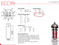
). It was designed for electric instruments, but you want to use it with a low impedance (line level) source.

3-band parametriq EQ (slim) - PCB
3-band parametriq EQ (slim) – PCB – TH custom effects

Would it suffice replacing the 1M input resistor and 1M pots for, say, 10k values, to have it 'properly' working? Or the whole chain of caps/resistor values (or even opamps) would have to be revised? Or, for instance, additional parts to be added?

Personally, I need a portable PEQ for experimenting with on-the-fly recordings..., Q control is very important for me. However, the closest I've found (analog and portable) are designs for guitars or high imp. instruments. Their size and 9v battery power supply are convenient, but I need low impedance to plug it to the line out of any mic preamp.

If this works, I thought it could be also interesting to use as a small PEQ stage between my DAC and active speakers. This might sound like non-sense or simplistic, but that simple is my knowledge here and I'm curious about what experienced listeners think about it. I have never used an analog PEQ before indeed, only digital filters.

If there are also any comments on the quality of the circuit itself, please let me know. Maybe the whole experiment would turn out in disappointment because of noise/phase shift or bandwidth control the design offers.

Thanks!
Domingo

Attachments

  • 3-band-parameq_V1.0.jpg
    3-band-parameq_V1.0.jpg
    690.2 KB · Views: 113
Projects by fanatics, for fanatics
Get answers and advice for everyone wanting to learn the art of audio.
Join the Community
507,750
Members
7,886,582
Messages

Filter

Forum Statistics

Threads
406,156
Messages
7,886,582
Members
507,750
Latest member
Jiboz